1
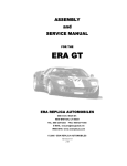
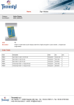
Please read and understand instructions before attempting installation Grifco *ELITE or EB1 Expansion Kit Installation Manual Rev: 509020 * Elite Kit pictured Contents: Page 2 Introduction Identifying your expansion board Installation Page 3 Connections(typical) Settings (typical) Page 4 Operation Page 5 Expansion Board Layout Diagram Page 6 DIP switch settings Page 7 Connections (advanced) Status LEDS Page 8 Warranty / Guarantee Grifco Advanced Users QUICK START GUIDE FITTING EXPANSION BOARD • Ensure power is OFF • Remove clear lid on main enclosure • Clip the 4 leg cradle into position • Attach the ribbon cable to the Expansion socket on the MCB (refer page 5-F12) CONNECTION OF EXTERNAL DEVICES (where applic) • Connect Auto/Man Controller using 6 metre cable (RJ45 socket) • Connect Obstruction Detection Devices • Connect External Access Controls etc. • Connect status outputs if applicable SETTINGS • Set obstruction behaviour jumpers on MCB accordingly • Set DIP switches if required (refer page 6) For a more detailed explanation on installation, setup, and operation please read booklet. Grifco Elite Users Manual Please read and understand instructions before attempting installation Introduction Congratulations on your purchase of the Grifco expansion kit. The Elite kit is typically aimed at satisfying the requirements of car parks, while the simple EB1 expansion kit will allow a vast range of functionality for many other door automation applications. Some features include: • Simple “plug-in” AUTO & AUTO/MANUAL modes (with ELITE kit) • Auto close with user settable delay (0 to 300 seconds) • Variable obstruction behaviour settings • Trigger input with variable door action sequences • Connection to industry standard 6 pin radio receiver cards • Independent variable radio card response actions • 4 status relays to allow connection to external devices • Emergency Services open and close inputs • Hard wire dedicated AUTO & MANUAL modes Elite kit shown fitted to Maestro Operator Identifying your ELITE or EB kit Included with your ELITE upgrade kit is: EB1 kit shown complete 1 x *Expansion Board pre-fitted with terminal blocks, jumper, cradle and ribbon cable 1 x *High Lid to accommodate added height in main control enclosure 1 x Auto/Manual Keyed Controller (optional) 1 x Hand Transmitter & Receiver Card (optional) 1 x PB009 Photo Beam & Reflector (optional) 1 x *Accessory Pack (including 2 x three way terminal blocks and 2 x jumpers) *EB1 – Basic Expansion Kit inclusions as per picture (right) Installation Installing Expansion Board To install the expansion board onto the main circuit board (MCB) of the Maestro: Turn off power to the Maestro operator Remove the clear lid covering the MCB Fit the MRC (Radio receiver) if required (refer to the GT4 & MRC manual included) Insert the cradle into the 4 locating slots surrounding the MCB cradle (low in the black enclosure base) Fit the ribbon cable into the socket labelled “EXPANSION” on the MCB Proceed to connect any external equipment or interfaces as required (following page) Fit high lid, and discard low profile lid Note: The elite expansion board requires either a photo electric beam or safety-edge bumper strip to be connected to the MCB, along with the corresponding jumper settings. Refer to the Maestro Standard Operator Manual for details on door behaviour settings. Grifco Elite Users Manual 2 Please read and understand instructions before attempting installation Connections (typical for Elite kit) Controller (Not included with EB1) The standard Elite kit features an AUTO/MAN Keyed Controller that is designed to simply plug into the RJ45 cable/socket in place of the standard controller. Refer to page 5 of the Maestro “Standard Operator” Manual for more details on plugging and mounting. Note: If you specifically require a stand alone MANUAL mode, you need to hard wire an AUTO/MAN key switch directly to the Expansion Board (refer page 5-K3). Obstruction Detection Devices (Photo Beams & Safety Bump Strips etc) The Expansion Board requires that at least one obstruction detection device is connected to the MCB to operate correctly. Refer to the Maestro “Standard Operator” Manual on page 10 for more information. You will find an additional 6 position terminal block and 2 x jumpers are included with the Elite Kit for interface and setup of the Standard Maestro Operator. Door Activation Inputs (Key Switches, Card Readers, Push Buttons etc) One of the most common inputs for a car park door operator is that which activates the door to open. This is generally connected to external / internal key switches, card readers, push button and the like to allow users to activate the door. If remote control is the only source of activation, these inputs will not be required. For connection detail refer to page 5-J1. Settings (typical for Elite kit) Typical Car Park Application For typical car park installations, all DIP switches and jumpers are to be OFF (ref below for definition) In Auto the door is generally operated by a push button, card reader or remote control etc to activate the door in an opening sequence. The door will then automatically close after a user settable time. The obstruction detection input will command the door to open to the fully open position and resume closing after the obstruction has cleared. The Auto Close timer will not be restarted unless another “open” input is received. The Auto close timer is a dial type pot located in the corner of the Expansion Board where the DIP switches are also found (refer page 5-J11). By default it is set up at a range of 5 – 30 seconds (clockwise to increase). Range can be increased to 5 minutes by fitting Jumper 1 (refer page 5-J6) For many alternate settings on the Expansion Board refer to page 6. Grifco Elite Users Manual 3 Please read and understand instructions before attempting installation Operation Assuming a typical installation, where all of the previous information has been carefully followed, the unit is now ready to be powered up. Before switching on power ensure the AUTO/MAN Controller is set to OFF and that no person is in the path of the door. Once the unit has been powered up a series of LEDS will display a boot up sequence. Afterwards the lights will indicate the status of the expansion board (refer page 7 for Status LEDS). AUTO or AUTO/MAN Key Selected Modes The AUTO/MAN Keyed Controller has these two distinct modes that will behave as follows: AUTO/MAN – combined IMPORTANT NOTE: This will be the behaviour if using a simple EB1 kit with existing UP/STOP/DOWN Controller This mode will allow use of the UP, STOP, DOWN and SET buttons on the Controller. You would use this mode for setting of limits and performing any routine maintenance on the door. It must be noted that the MANUAL use of the push buttons will temporarily disable any AUTO inputs such as transmitters and card readers for a period of 30 SECONDS. After this time the door will resume normal AUTO functions. For details relating to manual operation, including limit setting, refer to the “Maestro Standard Operator Manual”. Note: In the default (factory set) mode, Auto Close will occur immediately after setting upper limit. AUTO - only AUTO only is selected when the door is in normal operations, where the user does not want to allow use of the UP and DOWN buttons on the Controller. The only button to function on the Controller will be STOP. The STOP but will halt the Maestro Operator for approximately 30 seconds, then resume its normal functions after that. Note: Auto functions will resume 30 seconds after the key switch has been turned from OFF to AUTO or AUTO/MAN. This delay also exists after pressing STOP. CAUTION – EXTREME CARE SHOULD BE TAKEN BY SERVICE PERSONELL. MOTOR CAN START WITHOUT WARNING IN AUTO & AUTO/MAN KEY SWITCHED MODES. CAUTION - THE ONLY WAY TO ENSURE THE MAESTRO OPERATOR WILL NOT START WITHOUT WARNING IS BY KEY SELECTING “OFF” OR SWITCHING OFF MAINS POWER. DANGER! MAINS POWER SHOULD ALWAYS BE SWITCHED OFF BEFORE CARRYING OUT SERVICING TO ANY PART OF THE MAESTRO OPERATOR OR CONTROL SYSTEM. Grifco Elite Users Manual 4 Please read and understand instructions before attempting installation Layout The diagram below show the various inputs, outputs and components found on the Expansion Board. Throughout this manual, alpha-numeric references may be made to certain areas. Simply follow the grid locations to see the area being referred to. Grifco Elite Users Manual 5 Please read and understand instructions before attempting installation DIP switch settings Setting the expansion boards behaviour is done by adjusting 16 dipswitches located on it (refer page 5-K8). To adjust the expansion boards settings follow the table below. EB setting Dipswitches EB mode source Setting SW1 Factory Set> Auto Close Disable Factory Set> AUTO with MCB Over-ride ON Use MANUAL-OFF-AUTO Switch SW2 Factory Set> Obstruction Behaviour OFF OFF Auto Close ENABLED ON Auto Close DISABLED SW3 SW4 OFF OFF OFF ON Stop and retract while obstruction remains ON OFF Stop with 2 second retract only ON ON Stop Door Close Retry Stop and retract to last upper limit SW5 Factory Set> Vehicle Close OFF Door will close after obstruct behaviour concludes ON Door Close Retry DISABLED, only Auto Close will close the door after obstruction behaviour, and time out concludes SW6 Factory Set> Open Button Behaviour Factory Set> Receiver Behaviour Factory Set> *Trigger Input Behaviour Factory Set> * Trigger is 24VDC input Status Relay 3 Function Factory Set> Status Relay 4 Function Factory Set> OFF Vehicle Close DISABLED ON Door will close after obstruction clears, whilst open, opening or closing SW7 SW8 OFF OFF Open only, stop and open when closing OFF ON Reverse direction during opening and closing ON OFF Stop during opening, reverse during closing ON ON Press to Stop, then again to reverse during opening and closing SW9 SW10 OFF OFF Open only, stop and open when closing OFF ON Reverse direction during opening and closing ON OFF Stop during opening, reverse during closing ON ON Press to Stop, then again to reverse during opening and closing SW11 SW12 OFF OFF Close OFF ON Door will open to third limit ON OFF Door will go to open limit and remain while input remains held ON ON Custom Input via Parameters (Default - delay close as per timer pot) SW13 SW14 OFF OFF ON when Door Moving OFF ON ON when Door Moving, with 1Hz Oscillation ON OFF ON Door Moving, 1 minute Time Extension ON ON Custom (Default- on during obstruction, stays on for 2 sec after clear) SW15 SW16 OFF OFF Relay is on when Service Required OFF ON Relay flashes every second when service is required ON OFF Unlock function ON ON Custom Settings (Default – On if door has not closed for >5mins) Grifco Elite Users Manual 6 Please read and understand instructions before attempting installation Connections (advanced) External Trigger Input An external trigger can be installed to give more control over the Maestro. Once installed the trigger can be used to open/close the door, go straight to third limit if set, hold open or delay close. By default the trigger is 24VDC input, however by fitting the “contact” jumper next to the terminals (Page 5-H4) you will switch to “voltage free” input. The behaviour of the trigger is set via the on board dipswitches. Refer to Trigger Input Behaviour on page 6. Status Relays Four status relays located on the expansion board allow external devices, such as lights, sirens, solenoids to be activated in various ways. Relays 1 and 2 are set to activate when door is OPEN and CLOSED respectively. Relays 3 and 4 can be configured via dipswitches (refer page 6). Each relay has a common, normally open, and normally closed connection 6 Pin Receivers / Antenna Located on the expansion board is a 6 pinned header to suit industry standard 6 pin receiver cards (page 5-A7). Other style radio cards can be plugged in directly via the 3 position EXTERN RADIO terminals (page 5-A10). An ANTENNA can be wired to the adjacent terminals (page 5-A5) Emergency Input Controls These inputs are used in case of an emergency. They will open or close the door in all operating modes except OFF, overriding all other inputs. If an obstruction is detected during an emergency close, the operator will attempt to re-close after the obstruction is removed, regardless of the ‘Door Close Retry’ settings. The connection points for the emergency inputs can be found on page 5-I3. Extended Limit Input When using 3 limit positions (Ref. Maestro Standard Operator Manual), you can connect a dedicated input switch to the EXT.LIMIT terminals (page 5-K4). A pulse at these terminals will send door to the upper most limit. This can be convenient where a door is used for both passenger cars and large trucks (e.g. the truck would have a specific key switch to use for full opening of the door). Status LEDS (refer page 5-E5) LED Description Close Colour Red Display Solid ON Flashing Solid ON Flashing = = = = Status Closed Closing Open Opening Open Green Error Yellow Solid ON = EB failed Communications Orange Solid ON = “ “ “ 1 flash 2 flash 3 flash = = = EB to MCB comms error 24vdc b/up power detected Incompatible limits No limits Set “ “ 4 flash 5 flash = = MCB latch setting error EB ignored by MCB Grifco Elite Users Manual 7 Possible Solution Power OFF&ON if still error, replace EB Check ribbon connection or replace EB Not an error, waiting for mains to resume Reset limits Set Limits Check PLAT or BLAT jumpers on MCB Check MCB for errors Please read and understand instructions before attempting installation Grifco Elite Users Manual 8