1
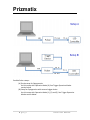
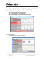
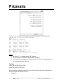
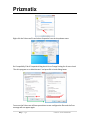
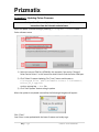
Prizmatix For initial testing of the Pulser device, connect the Pulser TTL Out to TTL input connector on the Prizmatix LED Current Controller and set the following parameters: On Train Settings Tab: Total # (numbers) of Trains (for example 10) P1D – Pulse 1 Duration [msec] (for example 200) P1I – Pulse 1 Interval [msec] (for example 200) Select Operation Mode: (0) Execute pulse sequence after START On Group Settings Tab: Set Total # (number) of Groups (for example 1) 13 | P a g e Pulser User Manual