1
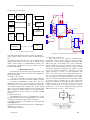
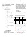
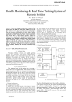
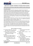
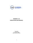
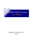
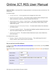
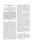
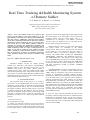
P. S. Kurhe et al, / (IJCSIT) International Journal of Computer Science and Information Technologies, Vol. 5 (3) , 2014, 4325-4330
Real Time Tracking & Health Monitoring System
of Remote Soldier
P. S. Kurhe , K. V. Karad , A. S. Chavan
Department of Electronics and Telecommunication,
SRES’ College of Engineering, Kopargaon.
University of Pune, (M.S.) India.
Abstract— Every year Soldiers become lost or injured. This
project gives the ability to track where Soldiers are at any
given moment. Search and rescue efforts become minimized in
time and resources. Additionally, with alert feature Soldiers
will be able to communicate their distress with GPS coordinate
information. Location tracking has been of great importance
since World War II, when military planners realized its
usefulness for targeting, fleet management, positioning, and
navigation. I have designed a reliable, energy efficient remote
soldier monitoring system. It is able to send parameters of
soldier in real time. It enables the army station to monitor
soldier’s parameters (temp, heartbeat, location) in real time.
Here the parameters of soldiers are measured continuously
(temp, heartbeat, location) and wirelessly transmitted using
GSM.
Keywords— ARM, GSM, GPS, Sensors, LCD.
I. INTRODUCTION
Nowadays Defence services are rapidly growing
towards new innovation with advance implementation.
Soldier’s health is more important because they are the
defenders who protect our country [1].The system is
composed of two parts, which are portable remote soldier
unit and the monitoring centre. The portable remote soldier
unit consists of Advanced RISC Machines (ARM) with the
embedded operating system, GPS and a GSM, temperature
sensor and heart bit arte sensor [1].
II. A COMPLETE SYSTEM
The proposed work of this project is to develop a
system that can be supplemented with real-time wireless
monitoring systems which are designed and implemented
through GPS network and are able to record and transmit
bio-signals of soldiers. The aim of this project is to provide
a medical monitoring for the soldier at any time and any
place and to design a soldier tracking system using GSM
and GPS to provide wireless system for monitoring the
parameters of soldier are as – Body temperature & Blood
pressure.
A. System Architecture
It is composed of two parts
1) Soldier unit: This unit consists of two types of sensors
such as temperature sensor, pulse rate sensor. These sensors
are used to measure the signals from the human body such
as heat signal, heart bit. After measurement, these analog
www.ijcsit.com
signals are converted into digital signals and compared with
the actual signals. If any discrepancy occurs between the
measured signals and the actual signals, then it is
considered as an emergency. The ARM 7 LPC2148
processor plays an important role in controlling all the
devices. It has an inbuilt A\D convertor.
GSM transmitter is used to transmit the signals from
the sensors which are controlled by the ARM7
microprocessor. GPS system is used to locate the position
of the soldier. It is very helpful for the army station to
rescue the soldier as soon as the emergency signal is
received. The ARM7 family includes the ARM7TDMI,
ARM7TDMI-S, ARM720T, and ARM7EJ-S processors.
The ARM7TDMI core is the industry’s most widely used
32-bit embedded RISC microprocessor solution. Optimized
for cost and power-sensitive applications, the ARM7TDM
solution provides the low power consumption, small size,
and high performance needed in portable, embedded
applications [1].
The ARM7TDMI-S core is the synthesizable version of
the ARM7TDMI core, available in both VERILOG and
VHDL, ready for compilation into processes supported by
in-house or commercially available synthesis libraries.
Optimized for flexibility and featuring an identical feature
set to the hard macro cell, it improves time-to-market by
reducing development time while allowing for increased
design flexibility, and enabling >>98% fault coverage. The
ARM720T hard macro cell contains the ARM7TDMI core,
8kb unified cache, and a Memory Management Unit (MMU)
that allows the use of protected execution spaces and virtual
memory. This macro cell is compatible with leading
operating systems including Windows CE, Linux, palm OS,
and SYMBIAN OS [1].
2) Army unit: Upon receiving the SMS, the VB s/w sorts
the solder’s location based on the GPS co-ordinates also the
health status is displayed. In this way the army official’s
can keep a track of all their solders. Similarly, Army officer
can also send reply to the corresponding soldier through VB
screen in terms of SMS.
4325
P. S. Kurhe et al, / (IJCSIT) International Journal of Computer Science and Information Technologies, Vol. 5 (3) , 2014, 4325-4330
B. Block Diagram Description
VCC_3.3V
R1
HEART
BIT
SENSOR
INSTRUME
NTATION
AMPLIFIER
10K
C5
22pF
LCD
RESET
XTAL2
Y1 12MHZ
C6
C7
XTAL1
0.1uF
22pF
XTAL1
XTAL2RESET
TEMP.
SENSOR
ARM
LPC
2148
2x2
KEY
BOARDS
RS 232
64636261605958575655545352515049
1
2
3
4
5
6
7
8
9
10
11
12
13
14
15
16
GSM
MODULE
GPS
ANTENNA
VCC_3.3V
GND
VCC 5V
GPS
RECEIVE
R
R1
LCD CONN
10 OHM
VCC 5V
3
2
1
P1.31
P1.26
VDD
VSS
P0.2
VCC 5V
PULSE RATE
LPC2148
VVSS
T
VSSAP1.29 P1.30
P1.27
VREF
XTAL1
P0.20/SSEL1
OSI1
LCDRS
1
48
P1.20 47
LCDEN
2 P0.21/AD1.6
P0.17
3 P0.22/AD1.7
46
P0.16/EINT0
4 RTCX1
45
P0.15/EINT2/AD1.5
5 P1.19
44
P1.21 43 VCC_3.3V
VCC_3.3V
6 RTCX2
VDD 42 GND
GND 7 VSS
VSS 41
8 VDDA
P0.14/EINT1/SDA1
LD4 9 P1.18
40
P1.22
LD5 10 P0.25/AD0.4
39
P0.13/AD1.4
EMER1
LD6 11 P0.26/AD0.5
38
P0.12/AD1.3
EMER2
12 P0.27/AD0.0
37
P1.17
P0.11/SCL1
EMER3
LD7 13
36
P1.23
P0.28/AD0.1
EMER4
14
35
P0.10/AD1.2
15 P0.29/AD0.2
34
P0.5/MISO0/AD0.7
16 P0.30/AD0.3
33
P1.16
P1.25/EXTIN0 P0.8/TXD1
.4/AD0.6
XD0
P0.1/RXD0
EMERGENCY KEYBOARD
1
2
3
4
5
P1.24
17181920212223242526272829303132
VCC_3.3V
TXD0
RXD0 GND
GND
5V
10uF
+
U5
1
+
VCC 5V
2
10uF
3
2
1
3
4
+
10uF
BODY TEMP
GSM
MODULE
PC
5
6
+
10uF
5V
16
C1+
VCC
V+
GND
C1-
14
TXD PC
C2+
13
RXD PC
15
C2-
12
TXD UC
V-
11
RXD UC
7
10
TXD PC RXD UC
8
9
RXD PC TXD UC
RS 232
GPS CONN
5V
1
GPS TXD 2
GPS RXD 3
4
Fig. 1 Block Diagram of System
The above block diagram shows the overall co-ordination
of the system. It shows how the concept is implemented as
the
real time application.Here there are 2 units under hardware
design part:1) Soldier unit: This unit is placed on the
soldier. It has mainly 3 parts:Biomedical sensors, Key
keypad, GPS + GSM unit 2) Army unit: This unit consists
PC with GSM module.
PC CONN
5V
1
PC TXD 2
PC RXD 3
4
Fig .2 Basic Circuit diagram of this proposed system
C. Temperature Sensor Lm35
The LM35 series are precision integrated-circuit
temperature sensors, whose output voltage is linearly
proportional to the Celsius (Centigrade) temperature. The
LM35 thus has an advantage over linear temperature
sensors calibrated in ° Kelvin, as the user is not required to
subtract a large constant voltage from its output to obtain
convenient Centigrade scaling [8]. The LM35 does not
III. DESIGN DESCRIPTION
require any external calibration or trimming to provide
All the design of proposed system are described in the typical accuracies of ±1⁄4°C at room temperature and
following.The figure 2 shows the basic circuit diagram of ±3⁄4°C over a full −55 to +150°C temperature range. Low
this proposed system.
cost is assured by trimming and calibration at the wafer
A. Hardware Description
level. The LM35’s low output impedance, linear output,
The heart of system is microcontroller which will and precise inherent calibration make interfacing to readout
access the data. In our project we will use ‘ARM’ controller. or control circuitry especially easy. It can be used with
To measure temperature of soldire there will be a single power supplies, or with plus and minus supplies. As
temperature sensor. To convert the output of sensor into it draws only 60 μA from its supply, it has very low selfelectrical form we will use signal conditioning (transducer). heating, less than 0.1°C in still air. The LM35 is rated to
As controller operates only on digital data, so this analog operate over a −55° to +150°C temperature range, while the
data is to be converted into digital form by using ADC. But LM35C is rated for a −40° to +110°C range [8].
ADC is inbuilt in ARM processor. So the output of the
signal conditioner circuit is directly connected to ARM
processor.
B. ARM 7- LPC 2148
The ARM7EJ-S processor is a synthesizable core that
provides all the benefits of the ARM7TDMI – low power
consumption, small size, and the thumb instruction.
• Operating systems such as Windows CE, Linux, palm OS
and SYMBIAN OS.
• More than 40 real-time operating systems, Including qnx,
Wind River’s vx works.
LPC2148 Micro controller:
www.ijcsit.com
4326
P. S. Kurhe et al, / (IJCSIT) International Journal of Computer Science and Information Technologies, Vol. 5 (3) , 2014, 4325-4330
D. Heart Beat Sensor
Heart beat sensor is designed to give digital output of
heat beat when a finger is placed inside it. This digital
output can be connected to ARM directly to measure the
Beats per Minute (BPM) rate. It works on the principle of
light modulation by blood flow through finger at each pulse.
Fig . Heart Beat Cavity Measurement System
•
•
send SMS content : coordinate
send the message issue Crtl-Z char (0x1A)
<CR>: carrier return character (0x0D hex)[4].
Fig:3 GPS Receiver
ICLM358is used for Heart Beat Sensor. Its dual low
power operational amplifier consists of a super bright red
LED and light detector. One will act as amplifiers and
another will be used as comparator. LED needs to be super
bright as the light must pass through finger and detected at
other end. When heart pumps a pulse of blood through
blood vessels, finger becomes slightly more opaque so less
light reached at the detector. With each heart pulse detector
signal varies this variation is converted to electrical pulse
[2].
E .GPS Receiver: GPS Module
The GPS smart receiver features the 16 channels
.Ultra low power GPS architecture. This complete enabled
GPS receiver provides high position, velocity and time
accuracy performances as well as high sensitivity and
tracking capabilities. The hardware interfaces for GPS units
are designed to meet NMEA requirements. The GPS
receiver provides data in NMEA 0183format with a 1Hz
update rate. Generally message received by GPS is in
NMEA [National Marine Electronics Association] message
format and NMEA protocol which is most commonly used
is NMEA0183 protocol. GPS sentences beginning with the
following specifications:$GPGGA, $GPGSA, $GPGSV,
$GPRMC, and $GPVTG. And sentences also begins with
$GPMSS, $GPZDA as shown in [table 1].
1) The Method of Tracking: The tracking method is based
on the process of collecting continuously the coordinate
(latitude, longitude) of mobile vehicle that could get from
GPS receiver. After getting the coordinate, the mobile
vehicle will send it to the supervised center via SMS or
GPRS service. The supervised center will receive the
coordinate of the mobile vehicle then displays on the
screen. The mother board on the mobile vehicle is equipped
a GSM modem- GM862 and it is directed by a 32bits
microcontroller ARM Cortex M3-LM3S2965. The
microcontroller uses serial interface to communicate with
GM862 by AT commands and send current position of the
vehicle via SMS service by send the sequences commands
below:
2) Commands:
• AT+CMGF=1<CR>
• AT+CMGS=”0937856377”<CR>
www.ijcsit.com
3) Specifications:
• 16-channels GPS search engine
• Ultra low power design (38mA, typical)
• Compact size
• Built-in low noise, high gain active antenna
• Super-cohesive magnetic for installation
• High sensitivity (up to -152dBm typ)
• Apply to host devices with USB or RS232
4) Applications:
•
Automotive
• Personal/Portable Navigation (PDA)
• Geographic Surveying
• Sports and Recreation
5) Benefits to User:
• Ultra low power consumption
• Easy and fast to install
• Superior urban canyon performance
• Low cost with high performance
F. GSM HARDWARE
The core of data communication about this system lies
in wireless communication control terminals that uses GSM
Modules to transfer long-distance data extensively and
reliably. It Support instructions of AT commands. SIM300
can be integrated with a wide range of applications.
SIM300 is a Tri-band GSM/GPRS engine that works on
frequencies EGSM 900 MHz, DCS 1800 MHz and
PCS1900 MHz SIM300 provides GPRS multi-slot class 10
capabilities and support the GPRS coding schemes CS-1,
CS-2, CS-3 and CS- 4. With a tiny configuration of 40mm
x 33mm x 2.85 mm, SIM300 can fit almost all the space
requirement in our application. Therefore, the MCU can
connect with GSM modules very expediently through serial
interfaces.
Fig. 4. GSM module
4327
P. S. Kurhe et al, / (IJCSIT) International Journal of Computer Science and Information Technologies, Vol. 5 (3) , 2014, 4325-4330
IV. SOFTWARE DESIGN
This includes the coding of ARM 7 processor and
coding for downloading of data and for GUI (Graphical
User Interface) on server side.
For ARM 7 :Embedded c using Keil software.
For GUI :VB.Net
VI. PARFORMANCE ANALYSIS
A. Performance characteristics of system
• Range of communication is unlimited due to the
use of GPS and GSM communication systems.
• As I am using GPS as guider, soldier can be secure
to use appropriate guidelines.
• Using GSM SMS facility, it is not necessary to
transmit any audio signals. These SMS are
depending upon the present condition of soldier.
• As my system is monitoring parameters regarding
with the help of soldiers, it is bit easy to provide a
medical services as per requirements.
• It is possible to get a resolution less than 100
meters by using super software that being used by
foreign countries.
• As 3 stage pipelining used by ARM, execution
speed of operation bit high.
• After each 60 seconds parameters regarding with
the health of soldier will be send, so in time we
can say a real time operating system.
B. Performance Analysis for temperature sensor LM35
TABLE I
ANALYSIS OF COLLECTED DATA FOR LM 35 IN SPECIFIC
CONDITION
Sr.
No.
1.
2.
3.
4.
5.
Condition of set
Temperature in
ºC
Air Conditioner
25
Normal Room at
33
Open ground at
1:00 pm
By using Fire
stick kept near to
LM35
Freezer bottle
with water
Readings
from
Thermometer
Output of LM
35 in ºC on
LCD
23
24.6
31
32.8
37
36.8
70
73.6
17
17.4
FIG. 5. FLOW CHART
V. ADVANTAGES OF SYSTEM
•
•
•
•
Provides high level safety to human life
Suitable for Indian conditions
Easy retrieval of data for the cause of incidents.
low cost and less complex system for installing
and application.
www.ijcsit.com
Fig.4 Comparison of LM 35 Readings on LCD with
Thermometer readings.
4328
P. S. Kurhe et al, / (IJCSIT) International Journal of Computer Science and Information Technologies, Vol. 5 (3) , 2014, 4325-4330
C. Analysis for Pulse rate sensor
TABLE II
ANALYSIS OF SENSOR DATA FOR DIFFERENT SITUATION
Sr.
No.
Condition for
reading
Output of sensor in terms
of Pulses on LCD
INVALID FINGURE
PRESS
1.
Improper placement
2.
Without finger
006
3.
At normal
78-88
4.
After running of
500 meters
92-120
D. Check functionality of GPS module for different
distance
TABLE III
ANALYSIS OF GPS MODULE FOR DIFFERENT DISTANCE
Sr.
No.
Distance in
Meter
Initial
condition
Name of
location
2.
3000
Computer Lab.
3.
3000
PG LAB
4.
3000
At Hostel.
1.
Kopargaon
GPS module Coordinates
1988.339 N
7448.339 E
1988.8390N
7548.0803E
1988.8390 N
7548.0803E
1988.839 N
7548.080 E
E. Checking GSM modem with respect to time
FIG. 6 PRACTICAL RESULTS
VII. CONCLUSIONS
From the above designed project I can conclude that
ANALYSIS OF GSM MODEM WITH RESPECT TO TIME
we are able to transmit the data which is sensed from
remote soldire to the server PC by using wireless
Sr. No.
Parameters
Time required
transmission technology GPS. It is completely integrated so
that it is possible to track anytime from anywhere. It has
15-20 seconds after
1.
Initializations
real-time capability, emerges in order to strengthen the
applying power.
relations among people. The accuracy of system is affected
NORMAL
9-12 seconds to deliver
2.
by some factors such as weather, environment around the
Message
after sending message
mobile soldire unit, GPS receiver, compass sensor and the
Emergency
9-12 seconds to deliver
variation between True North Direction and Magnetic
3.
Message
after sending message
North Direction, etc. The future works include optimizing
Message from
9-12 seconds to deliver
the hardware system, choosing a suitable GPS receiver and
4.
Army station
after sending message
compass sensors. Improving the routing algorithm can be
improved by neural network. This system has many
VII. RESULTS
advantages such as large capability, wide areas range, low
We continuously scan for various parameters of soldier, operation costs, effective, Strong expandability and Easy to
such as latitude, longitude temperature, pulse rate, and use. Upgrading this setup is very easy which makes it open
massages. The μC stores all this data in the internal memory. to future a requirement which also makes it more efficient.
TABLE V
www.ijcsit.com
4329
P. S. Kurhe et al, / (IJCSIT) International Journal of Computer Science and Information Technologies, Vol. 5 (3) , 2014, 4325-4330
VIII . FUTURE ENHANCEMENT
There is always chance to improve any system as
research & development is an endless process. The
following measurements can be done in future:
Pulseoximetry and, Galvanic-Skin Resistance Amenia.
1. Soldier Voice Recognition system: IC HM2007 can be
used to recognize the voice samples of the soldier, for better
security purpose.
2. A Camera can be fitted into the system so as to enable
the base station to get a real time view of the battlefield.
3. Automatic Surveillance Robot: A Robot with all the
medical features as well as advanced features like
ammunition can be build.
REFERENCES
[1]
[2]
[3]
[4]
[5]
[6]
[7]
[8]
[9]
[10]
[11]
[12]
Ushasree.K, Hameed Pasha, “Protection system for VIP’S with
GPRS & Remote monitoring”, International Journal of Computer
Trends and Technology- volume2Issue2- 2011.
Rubina.A.Shaikh, “Real Time Health Monitoring System Of Remote
Patient Using Arm7”, International Journal of Instrumentation,
Control and Automation (IJICA) ISSN: 2231-1890, Vol-1 Iss-3,4,
2012.
N. Lakshmi Kanthan & V. Babu, “MCEP Based Intelligent Vehicle
with Multitask Management”, ISSN (Print): 2278-8948, Volume-1,
Issue-2, 2012 .
Abid khan, Ravi Mishra, “GPS – GSM Based Tracking System”,
International Journal of Engineering Trends and Technology
Volume3 Issue2- 2012.
Pooja Sathe, “Gprs Based Routing & Tracking Of Mobile Vehicles
Using Arm”, International Journal of Engineering Research and
Applications (IJERA) ISSN: 2248-9622 www.ijera.com Vol. 2,
Issue4, July-August 2012, pp.1088-1090.
Ya-lin Miao†, Xiang-lin Miao, Zheng-Zhong Bian , Yong-jie Zhan
“Design and Application of Embedded System Based on ARM7
LPC2104 Processor in Telemedicine”, Proceedings of the 2005
IEEE Engineering in Medicine and Biology 27th Annual
Conference Shanghai, China, September 1-4, 2005.
UM10139 Volume 1: LPC214x User Manual, Rev. 01 -15 August
2005, Philips Semiconductors.
LM35 datsheet, National Semiconductor Corporation DS005516,
http://www.national.com.
LPC2141/42/44/46/48,
Rev.5-12
August
2011,
http://www.nxp.com.
Hui Hu, Lian Fang “Design and Implementation of Vehicle
Monitoring System Based on GPS/GSM/GIS” Third International
Symposium
on
Intelligent
Information
Technology
Application ,School of Information Engineering, East China Jiao
Tong University, Nanchang, Jiangxi, China in 2009. Pages 278-279.
Thuong Le-Tien, Vu Phung-The “Routing and Tracking System for
mobile Vehicles in Large Area”, Fifth IEEE International
Symposium on Electronic Design, Test & Applications Dept. of
Electrical Electronics Engineering, HCM University of Technology,
Vietnam in 2010.
Umar Farooq, Tanveer ul Haq, Muhammad Amar, Muhammad
Usman Asad, Asim Iqbal “GPS-GSM Integration for Enhancing
Public Transportation Management Services” Second International
Conference on Computer Engineering and Applications,
Department of Electrical Engineering University of The Punjab
Lahore-54590, in 2010.
www.ijcsit.com
4330