1
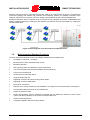
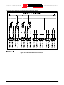
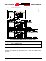
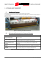
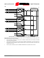
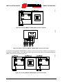
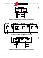
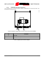
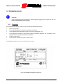
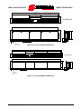
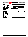
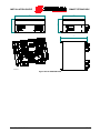
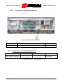
INSTALLATION GUIDE
SMART STRING BOX
Index of Figures
Figure 1: SMART STRING BOX Line ............................................................................................................ 9
Figure 2: SMART STRING BOX one-line diagram..................................................................................... 10
Figure 3: Block diagram of the first and second parallel levels ................................................................... 11
Figure 4: 16-input SMART STRING BOX ................................................................................................... 12
Figure 5: JUNCTION BOX for SMART STRING BOX with transparent lexan panel .................................. 22
Figure 6: DC-SWITCH BOX with opaque Lexan panel ............................................................................... 22
Figure 7: Packaging of SMART STRING BOX ............................................................................................ 23
Figure 8: SMART STRING BOX serial number ........................................................................................... 24
Figure 9: Composition of a SMART STRING BOX ..................................................................................... 25
Figure 10: DC-SWITCH BOX: internal view ................................................................................................ 26
Figure 11: DC-SWITCH BOX electrical diagram ......................................................................................... 27
Figure 12: DC-SWITCH BOX: bottom view ................................................................................................. 28
Figure 13: JUNCTION BOX: internal view .................................................................................................. 29
Figure 14: JUNCTION BOX: bottom view ................................................................................................... 30
Figure 15: JUNCTION BOX electrical diagram ........................................................................................... 31
Figure 16: SMART STRING BOX positioning and connection diagram...................................................... 32
Figure 17: Unpackaging of SMART STRING BOX ..................................................................................... 34
Figure 18: SMART STRING BOX................................................................................................................ 36
Figure 19: Incorrect SMART STRING BOX installation ............................................................................. 36
Figure 20: SMART STRING BOX with spacers for heat dissipation ........................................................... 37
Figure 21: Cabling recommended for the parallel string modules ............................................................... 40
Figure 22: Installation of cables with ferrule on terminal ............................................................................. 41
Figure 23: Fitting the string connection connector ...................................................................................... 42
Figure 24: String disconnection ................................................................................................................... 43
Figure 25: DC-SWITCH BOX position of cable glands ............................................................................... 44
Figure 26: Short circuit located downstream from the SMART STRING BOX ............................................ 45
Figure 27: Connection of the 3-wire PT100 thermistor................................................................................ 48
Figure 28: Anti-theft connection with separate anti-tampering and theft signalling ..................................... 50
Figure 29: Anti-theft connection with cumulative signalling for more than one SMART STRING BOX ...... 50
Figure 30: SPD status signalling connection diagram ................................................................................. 52
Figure 31: SPD and disconnecting switch status signalling connection diagram ....................................... 53
Figure 32: ELV zone dedicated to Modbus RS485 and environmental sensors communication ............... 55
Figure 33: Recommended multidrop connection diagram .......................................................................... 56
Figure 34: 8-string SMART STRING BOX connection diagram .................................................................. 57
Figure 35: Details of 8-string SMART STRING BOX connection terminals ................................................ 57
Figure 36: 16-string SMART STRING BOX connection diagram ................................................................ 57
Figure 37: Details of 16-string SMART STRING BOX connection terminals .............................................. 58
Figure 38: 24-string SMART STRING BOX connection diagram ................................................................ 58
Figure 39: Details of 24-string SMART STRING BOX connection terminals .............................................. 58
Figure 40: Communication line terminator DIP-switch ................................................................................ 61
Figure 41: 16-input SMART STRING BOX cablet ....................................................................................... 62
Figure 42: 24-input SMART STRING BOX cablet ....................................................................................... 63
Figure 43: FUSE BOX ................................................................................................................................. 64
Figure 44: B-F-8 FUSE BOX cover ............................................................................................................. 65
Figure 45: B-F-8 module: internal view........................................................................................................ 67
Figure 46: FUSE BOX module: bottom view ............................................................................................... 67
Figure 47: FUSE BOX electrical diagram .................................................................................................... 68
Figure 48: Diagram of negative pole connection of the strings to the FUSE BOX ...................................... 69
Figure 49: STRING BOX connection with optional fuse expansion box ..................................................... 70
Figure 50: FUSE BOX dimensions .............................................................................................................. 70
Figure 51: FUSE BOX wall mounting .......................................................................................................... 71
Figure 52: Surge Protective Device ............................................................................................................. 74
Figure 53: Fuse extraction using the fuse extractor .................................................................................... 80
Figure 54: Fuse installation using the fuse extractor ................................................................................... 80
Figure 55: SMART STRING BOX dataplate ................................................................................................ 85
Rev. 02 - 29/04/2013
5/106