1
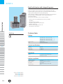
ASTATplus
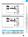
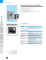
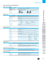
I/O terminal board specifications
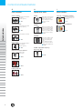
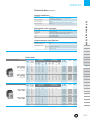
Power I/O terminals
Terminals
Function
1L1, 3L2, 5L3 Mains input
2T1, 4T2, 6T3 Motor output
A1, A2, B1, B2 Control voltage
Description
220/240VAC, +10%, -15%
Digital inputs
57
1
2
3
4
Common for
digital inputs
Run
This is a common terminal for the digital input terminals specified below
Run order. Command signal may be provided by one NO dry momentary contact to
terminals 1 and 57
Stop
Stop order. Command signal may be provided by one NC dry momentary contact to
terminals 2 and 57
NOTE: Run/Stop permanent command is allowed linking 1-57 and using one dry NO contact
to 2-57 terminals
Programmable input I3 These two inputs are programmable. Can be assigned to the following internal functions:
Programmable input I4
- soft stop
- DC brake
- linear ramp
- pump control
- slow speed control
- dual ramp selection
- kick start
- reverse slow speed - by-pass function
- override
- local / remote control
Command signal should be provided by one NC dry contact to terminals 57-3
or terminals 57-4.
By switching this contact ON/OFF it is possible to enable or disable the assigned function.
Digital outputs
11, 12, 14
23, 24
33, 34
Programmable relay 1r 11-12 = NC, 11-14 = NO dry contacts
This relay can be assigned to several internal output functions. As default assigned to
function RUN.
Programmable relay 2r 23-24 = NO dry contact
This relay can be assigned to several internal output functions. As default assigned to
function EOR.
Programmable relay 3r 33-34 = NO dry contact
This relay can be assigned to several internal output functions. As default assigned to
function DC BRAKE
Common for all relay output contacts:
Max. usage voltage:
380V AC (B300 - UL)
Thermal current Ith:
8A
AC-15:
220V / 3A, 380V / 1A
DC-15:
30V max. / 3.5A
Programmable relays can be assigned to following functions:
- End of Ramp
- RUN
- DC brake
- Slow speed
- Fault
- Undercurrent
- Undervoltage
- Overcurrent
- Overvoltage
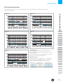
Analogue I/O
8
7
9
Analog input common (-) This is a common terminal for the analogue input terminal 7 and analogue output terminal 9
TG feedback input (+)
0-5V analogue input for speed feedback. It should be provided by a DC tacho-generator
coupled to motor.
This speed feedback signal is required when the «linear ramp» function is used.
Current output (+)
0-10VDC analog output for current measurement purpose. Ir correspond to 2Vdc.
Rated current is 2VDC. Load impedance 10kΩ or higher.
B
C
D
E
F
G
H
Motor thermistor input This inputs allow a motor thermistor with a response value from 2.8 to 3.2kΩ,
and a reset value from 0.75 to 1kΩ to control motor temperature.
When the motor thermistor is not used, a link must be used in terminals 5-6.
X
Communications
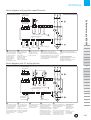
SG, TD, RD
A
I
Motor thermistor terminals
5, 6
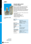
Soft starters up to 850 kW
3ph input voltage according ASTAT Plus voltage
Output terminals to 3ph AC motor
Input control voltage
110/120VAC, +10%, -15%
Gr, Tx, Rx data
- RS232C, 3 wires, half duplex. Maximum cable lengths 3m (10 feet)
- Asynchronous data transmission, 9600 Bauds, 1 bit start, 8 bits data, 1 bit stop, no parity
- Supported ASCII and ModbusRTU (selectable by the user)
- Optional Device Net and Profibus DP external modules
D.81