1
ß e nway
C-5 SYSTEM
G9 Villa Door Station Series
USER MANUAL
Please read this user manual carefully before using the products. Please keep
it for future reference.
(VER:V1 .10)
-
..
r:;--------------------------- ~-:!
\ 11
INSTALLATION TIPS
• The signal wires should be as far away as possible
from the interfering sourees.
• The signal wires should run on the low electronic
route and cannot go with the high electronic (e.g .
220V house power) route or transmission signal
route (e.g . CATV) in parallel.
• 00 not install the products in following situations.
• Humidity or rain
• Sun shine
• Shake or strike
• Dust
• High temperature
• Noise
This symbol warns people there is dangerous voltage
dose to the products. Be careful of shock.
This symbol warns people the note is very important. They
~
.
i
have to follow strictly in order for the system performs perfectly.
::J
Preface
Thankyou very much for using Genway products that were developed with
the latest technology. Tomeet the demands ofusers, Customer Satisfaction
is our goal.
Please read this manual carefully before using the products in order for the
products can perform perfectly. In an effortto serve you better, we we1come
any comments or suggestions you have.
Contents
1. Product lntroduction-:
1
2. Product Features· ··················································1
3. Specifications- :
···1
4. Appearance & Ports-»
···2
5. Diaqrarns-:
···3
Diagram for 1 door station & 1 indoor phone -r ••••••••••••••.••• "'3
Diagram for 1 door station & up to 4 indoor phones -: ••••••.•• "'4
Diagram for 2 door station & up to 3 indoor phones-: ••••••. , •••• 5
Diagram for e-Iocks-: •..•••••••••...•••..••••••.•••••••••••••••.•• "'6
6. lnstallatlon-:
···7
Door station- :
7
Power supply(4055)'"
8
Power supply(4001)&Distributor( 41108/4230)'"
8
Changing name taq-»
9
7. Camera Adjustment·············································1 0
8. Operation-
···11
9. Appendix: Prepare CAT.5 cable-:
Product list···
···13
···15
1.Product Introduction
o
This door station is apart of C-5 one cable system. It is for villa/single fam ily house
use. Simple one CAT.5 common wiring , making communication c1ear and trouble free.
One door station can be connected up to 4 indoor phones for a villa. Expandable to 2
door stations up to 3 indoor phones . And also available to connect with guard unit and
perimeter gate station. When there are many villas , they can be wired together in
network.
2.Product Features
• Vandal resistant panel, stainless steel construction, waterproof, flush mounting .
• Compatible with all audio and video indoor phones in C-5 system.
• Ooors can be released by various methods such as indoor phone , 10 card ,
SERVICE button , and EXIT button.
• Use1/3' CMOS color camera which isadjustable. The IR illumination ofters clear
image even in the dark .
• A sound system is programmed for friendly intercommun ication.
• The enclosed remote control provides easy programme.
3.Specifications
Model
Operating
voltage
Quiescent
current
(OC 35V)
Operating
Temperature
current
(OC 35V)
5403
OC35V
<:; 50mA
<:; 110mA
-40 °C-+70 °C
54030
OC 35V
<:; 50mA
<:; 130mA
-40 °C-+70°C
OC35V
<:; 50mA
<:; 160mA
-40 °C-+70°C
OC 35V
<:; 50mA
<:; 180mA
-40 °C-+70°C
5809
-------
-------
CCO&CMOS
PAL
5809-C
View angle :90°
58090
58090-C
Camera
> <
Adjustable angle :
± 10°
-
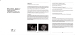
4.Appearance & Ports
• Face
Brand
®
@onway
®
S eaker
0000 00000 0000
00 0 00 0 0 0 0 0 0 0 0
000 0 0 0 0 0 00 0 0
00 00 0 0 0 0 0 00 00
0 0 0 0 0 0 00 0 00 0 0
Infrared LEO
&Camera
IR Oetector
...
[CALL) button
[OOOR OPEN) LEO
[SPEAK NOW) LEO
Card reader
&Name tag
[SERVICE) button
MIC
SPEAK OOOR
NOW OPEN
CALL SERVICE
®
®
• Back
.,
P
o Port to indoor phone/distributor
IIL
"
cl
SL
e
~
'"
"
e
e
I
c
Ir
DD DDID DD D
8
JP1 connector & software update port
f
JP1rr== = = = = = = = = =r:::;
~
0
'0
0
0
' 0
'0
0
~
0'
11
e
cl
e
1 2 3 4 15 6
78
01 1 01 VF· VF+IAF- AF+ GNO OC+
8 Port to electronic lock (options)
[INOOOR)&[GNO): to EXIT button
0
-
8
..........
-
e
8
e
-cm
"
GS INDOOR GNO
+12"
NO NC COM out
DDDDDDD
5.Diagrams
5.1 Diagram for 1 door station & 1 indoor phon e
1. When there are only one door station and
one indoor phone, the connector of JP1
has to create a short circuit across the two
pins.
2.Max. Distance: <100m
[In case longer,
please use an extra power supply on the
indoor phone.]
Power supply
Port in door station
Indoor phone
+
CX)
I"'
0
Brown
Z
<.9
Brown/white
0
0
+
co u,
«
U.
«
I
L()
.q
+
u,
>
I
(")
N
0
o
Blue/white
I
Green
I
R t - - Geee"lwhite
l0
~I
T""
T""
Blue
u,
>
I
0
CAT.5
0
Oea",e
Orange/white
1
Port in Ooor station
00
0
00
0
000
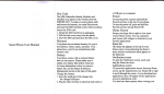
5.Diagrams
5.2 Diagram for 1 door station & up to 4 indoor phones
1.PORT1 ~ P O RT4 in the distributor are for 4
indoor phones (audio or video) .
2.Terminals in the distributor are useless here.
\,
3.Max. Distance : <100m
[In case longer,
please use an extra power supply on each
indoor phone.]
Indoor phone 4
Oistributor (411 OS)
0
0
0
0
0
0
0
0
DCt
GND
AFt
AF
VFt
VF
CAT.5
Indoor phone 1
LB
LA
CAT.5
Ooor station
Orange/white - -ti
Orange
Green/white - -+-I
Green
Blue/white
Blue
Brown/white
Brown
Power supply
> ~
5.Diagrams
5.3 Diagram for 2 door stat ion & up to 3 indoor phones
1.Connect 3 indoor phones and 2 door stations
as the diagram below.
2.Up, Down and PS terminals are useless here.
3.Max. Distance : <100m
[In case longer,
please use an extra power supply on each
indoor phone .)
Oistributor (4230)
,. -----I~r p~ne
CAT.5
3
I~
°
CI)
e il.
o
s:
N
Q. ~
' °
o
.g
11.
~
E ~
L 11.
O
N
§
~
~: ::Ja.
Vi
o
o
CAT.5
o
LB
LA
CAT.5
PS~
GND
3:
D
C+J
Power supply
Orange/white
0
~ ~
Orange
Green/white
Green
Blue/white
Blue
Brown/white
Brown
Ooor station 1
5<
Door station2
5.Diagrams
5.4 Diagram for e-locks
There are 2 wiring options for e-Iocks accordingly.
1. Release by POWER
2. Release by SIGNAL
I
INO
GS INOooR GNO
+1Z\)
NC COM out
NO (Normal Open ) style
I
I
GS INOOOR GNO
+1Z\)
NO NC COM out
NC (Normal Close) style
[Note] Apower supply is required for the e-Iock in NO or Ne style.
If use an e-Iock that is without motor, a reverse diode (the producer
/
recommends IN4007) is required . It is usually enclosed when delivering.
3.EX IT button
+1ZV
NO NC COM out
-
EXIT button
[Note] No polarity requ ired .
><
6.Installation
• Door station
Dimensions
150
@
106
@
o
!
o
o
N
I'
N
o
130
Product size:272 x 150 x 68.5
mm
Installation size :254 x 132 x 64 mm
Mounting
*Notes:
1. Mind the installation size while producing a groove for the back cover.
2. Control the depth of the groove carefully so that it is as same as the one of the
back cover.
3. We suggest the height between 1100mm and 1400mm. But please also consider
other situations such as view angle of the camera and disabled persons.
> <
6.Installation
• Power suppl y( 4055 )
Dimensions
Mounting
}
)
• Power supply( 4001 )&Distributo r(411 OS/4230 )
Dimensions
4110S
4230
4001
3 8 . 5~
152
e
\1'
"1
e
e
'<IT
ro
0
e
82
)
J
Mounting
I
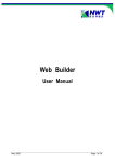
6.Installation
• Cha nging nam e tag
o
0
0 0
q
twJ
00
[J
0
' '*:'.:: ~ 2.0
3.Take out the name tag.
plastic.
and move to right.
o
in the plastic.
Name tag
2.Take off the
1.Push the right edge
4.Put the name tag
0
immmm
Plastic
r10l
"!d:: ~ ~
o
rJ
0
o
5.lnsert the right
edge into sideling.
o
o
6.Push the left edge
and move to left.
7.Finish.
7.Camera adjustment
"" •
"" . =
A:for up and down
I,
B:for left and right
,I
,
Left
Right
8.0peration
Please connect all necessary units according to the diagrams . When the door
station sounds "ON", it means the system is ready and you can use or program it.
•
Call
1.Press CALL button on the door station, the indoor phone chime tone sounds and the screen
turns on and displays the visitor image .
2.lf there is no answer, the door station will say "Sorry. There is no answer" and the system
will automatically reset to standby after 30s . If the line is busy, the door station will speak
"Sorry. It's busy now."
[Note:if want to cancel the call,press CALL button again.]
•
Answer
1.press© button on the indoor phone (hands-free) or pick up the handset to answer when
it rings. [SPEAK NOWj LED will flash at the same time .
2.PressS button on the indoor phone to release the door.
3.Press© button on the indoor phone (hands-free) or hang up the handset to end the talk.
[Note: The talk is allowed in 120s.]
OR
> <
o
8.0peration
•
Ooor release
There are tour methods to release the door.
1./ndoor phone: Press
8 button on the indoor phone to release the door.
2./0 Card: Put the registered eard on the eard reader (if there is) to release the door..
3.SERV/CE button : In the authorized time, press SERVICE button on the door station 10release
the door. [This button is special for postmen or other service people. The function has
to be programmed by the remote control, The remote control manual has details.]
4.EX/T button : Press the EXIT button (if there is) to release the door.
[Note:when the electronic lock ls released, the door station will say "the door opened"
and the [ODOR OPEN] LEO will flash at the same time.]
@
•
Scan mon i tor
1.Press
@
button on the (video) indoor phone while the system stands by, the sereen will
display the image in front of the door station.
2.Press
.
@ button again to end monitoring. But when there is another door station, if you
press the button at the 3rd time, it will display the image in front of that door station.
[Note:the image automatically turns off in approx. 15s. Ouring displaying, if somebody
presses the CALL button on the door station, the monitoring will end automatically.]
> <
Appendix 1
Prepare for CAT.5 cables with Rj45 connector
T568B standard is the most popular in network projects.
Materials and tools:
1II11l1l
RJ45 connector (8P)
CAT.5 or CAT.5E
8P wire Crimpers
Tester
'"
The C-5 system always uses CAT.5 or water-proof CAT.5E cables as the following
ill
pictures. 80th kinds of cables are required to be complied with the Internat
ional Standard «TIAl EIA -568-B.2-2001 Commercial Building Telecommunications
Cabling Standard Part 2: Balanced Twisted-Pair Cabling Components )) .
t
CAT.5
Water-proof CAT.5E
Sequence of wires in T568B standard:
1 2 34 5 6 7 8
1.0range/white
2.0range
3.Green/white
4.Blue
5.Blue/white
6.Green
7.Brown/white
8.Brown
12 34 5 6 78
Process charts
Step1 : Cut a wire which need to use
Step2:Cut the coat and take it off
Step 3: Collocate and range the wires
according to the sequence mentioned
above.
Step 4: Cut the wires to be orderly.Please
Step 5: Take a connector and keep the hook
Step 6:lnsert the connector into the tool
and press the tool to fi x the wires in the
connector.
adown and facing to your body. Insert the
mind the wires length to be about 15mm.
wires into the connector until all wires touch
Step 7: repeat Step 1 - Step 6 for another end of the cable.
Step 8: use the tester to test if the wires at two ends are conjoint weil and corresponding each
other at right sequence ..
<
Appendix 2
Product list
MODEL
FEATURE
Audio
Speech system , proximity
Port for EXIT button
Striking name tag
Easy pragram with remote contra 1
5403
Audio
Speech system , praximity
ID card reader , SERVICE button
Port for EXIT button
Striking name tag
Easy pragram with remote contral
54030
Video
Speech system , praximity
Port for EXIT button
Striking name tag
Easy pragram with remote contral
5809/5809-C
Video
Speech system , proximity
ID card reader , SERVICE button
Port for EXIT button
Striking name tag
Easy pragram with remote control
58090/58090-C
>