1
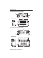
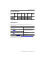
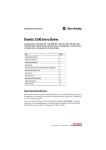
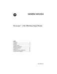
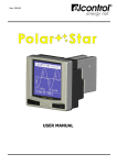
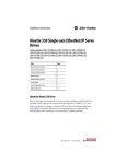
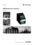
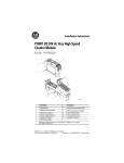
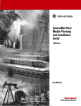
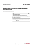
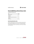
Installation Instructions
Kinetix 5500 AC Line Filters
Catalog Numbers 2198-DB08-F, 2198-DB20-F, 2198-DB42-F
Topic
Page
About the AC Line Filters
1
Important User Information
2
Before You Begin
3
Wire the AC Line Filter
4
AC Line Filter Specifications
7
Additional Resources
7
About the AC Line Filters
This publication provides installation instructions for the AC line filters used with Kinetix® 5500
servo drives. Use these instructions for installing and wiring your AC line filter. For more
information on installing and wiring your Kinetix 5500 drive, refer to the Kinetix 5500 Servo
Drives User Manual, publication 2198-UM001.
2 Kinetix 5500 AC Line Filters
Important User Information
Solid state equipment has operational characteristics differing from those of electromechanical equipment. Safety Guidelines for
the Application, Installation and Maintenance of Solid State Controls (Publication SGI-1.1 available from your local Rockwell
Automation® sales office or online at http://www.rockwellautomation.com/literature/) describes some important differences
between solid state equipment and hard-wired electromechanical devices. Because of this difference, and also because of the
wide variety of uses for solid state equipment, all persons responsible for applying this equipment must satisfy themselves that
each intended application of this equipment is acceptable.
In no event will Rockwell Automation, Inc. be responsible or liable for indirect or consequential damages resulting from the use or
application of this equipment.
The examples and diagrams in this manual are included solely for illustrative purposes. Because of the many variables and
requirements associated with any particular installation, Rockwell Automation, Inc. cannot assume responsibility or liability for
actual use based on the examples and diagrams.
No patent liability is assumed by Rockwell Automation, Inc. with respect to use of information, circuits, equipment, or software
described in this manual.
Reproduction of the contents of this manual, in whole or in part, without written permission of Rockwell Automation, Inc., is
prohibited.
Throughout this manual, when necessary, we use notes to make you aware of safety considerations.
WARNING: Identifies information about practices or circumstances that can cause an explosion in a
hazardous environment, which may lead to personal injury or death, property damage, or economic loss.
ATTENTION: Identifies information about practices or circumstances that can lead to personal injury or
death, property damage, or economic loss. Attentions help you identify a hazard, avoid a hazard and
recognize the consequences.
SHOCK HAZARD: Labels may be on or inside the equipment, for example, drive or motor to alert people
that dangerous voltage may be present.
BURN HAZARD: Labels may be on or inside the equipment, for example, drive or motor to alert people
that surfaces may reach dangerous temperatures.
IMPORTANT
Identifies information that is critical for successful application and understanding of the product.
Rockwell Automation Publication 2198-IN003A-EN-P - July 2012
Kinetix 5500 AC Line Filters 3
Before You Begin
For general guidelines when laying out your panel and mounting your AC line filter, refer to the
System Design for Control of Electrical Noise Reference Manual, publication GMC-RM001.
For guidelines specific to your application, refer to the Kinetix 5500 Servo Drives User Manual,
publication 2198-UM001.
ATTENTION: To avoid personal injury or damage to equipment due to hazardous voltages,
follow these guidelines when installing your AC line filter. NEC and local regulations always
take precedence.
• Disconnect mains power prior to installation.
• Verify that the rated voltage is compatible with the local supply voltage.
• Connect the earth ground connection first when making connections.
Install the AC Line Filter
Mount the line filter to the cabinet panel with hardware as specified in the table below.
Cat. No.
Mounting Bolts
Torque Value
N•m (lb•in)
M5 (#10-32)
2.0 (17.7)
M6 (1/4x20)
4.5 (39.8)
2198-DB08-F
2198-DB20-F
2198-DB42-F
Refer to the System Design for Control of Electrical Noise Reference Manual, publication
GMC-RM001, for proper high-frequency (HF) bonding techniques to improve overall system
performance.
Rockwell Automation Publication 2198-IN003A-EN-P - July 2012
4 Kinetix 5500 AC Line Filters
Wire the AC Line Filter
Wire should be copper with 75 °C (167 °F) minimum rating. Phasing of main AC power is
arbitrary and earth ground connection is required for safe and proper operation.
IMPORTANT
The National Electrical Code and local electrical codes take precedence over the values and
methods provided.
IMPORTANT
When wiring the line filter for single-phase operation, do not make connections to the L3
terminals. Line and load designations must be observed to meet product specifications.
Wiring Examples for the AC Line Filter
Input Fusing
240/480V
L1
L2
L3
PE
Mains AC Input
2198-DBxx-F
AC Line Filter
Line
L1’
L2’
L3’
PE
L1
L2
L3
Kinetix 5500 drive input
power (IPD) connections
for three-phase operation.
L1
L2
L3
Kinetix 5500 drive input
power (IPD) connections
for single-phase operation.
Load
Bonded Cabinet
Ground Bar
Input Fusing
240V
L1
L2
L3
PE
Mains AC Input
2198-DB08-F
AC Line Filter
Line
Bonded Cabinet
Ground Bar
Rockwell Automation Publication 2198-IN003A-EN-P - July 2012
L1’
L2’
L3’
PE
Load
Kinetix 5500 AC Line Filters 5
Wiring Specifications
Kinetix 5500
Drive Cat. No.
Connects to
Terminals
Line Filter
Cat. No.
Pin
Signal
Recommended (1)
Wire Size
mm2, AWG
AC Line Filter
Strip Length
mm (in.)
Terminal
Torque Values
N•m (lb•in)
7.5 (0.30)
0.8 (7.1)
2198-H003-ERS
2198-H008-ERS
2198-DB08-F (2)
IPD-1
IPD-2
IPD-3
IPD-4
2198-H015-ERS
2198-H025-ERS
2198-DB20-F
2198-H040-ERS
2198-H070-ERS
(1)
(2)
L1
L2
L3
1.5…4
(16…12)
9.0 (0.35)
2.0 (17.7)
1.5…6
(16…10)
2198-DB42-F
12.0 (0.47)
The actual gauge of the input power wiring depends on the system configuration. Consult your machine builder, the NEC, and applicable local
codes.
Applies to installations with single-phase or three-phase input power.
AC Line Filter Dimensions
AC Line Filter Dimensions (catalog number 2198-DB08-F)
167
(6.57)
8.5
(0.33)
Ø 6.0
(0.24)
32
(1.26)
Dimensions are in mm (in.).
79
(3.11)
173
(6.81)
151
(5.94)
60.8
(2.39)
M5
1.2
(0.05)
46
(1.81)
R3.0
(0.12)
179
(7.05)
Rockwell Automation Publication 2198-IN003A-EN-P - July 2012
6 Kinetix 5500 AC Line Filters
AC Line Filter Dimensions (catalog number 2198-DB20-F)
8.5
(0.33)
R3.0
(0.12)
217
(8.54)
Ø 6.0
(0.24)
42
(1.65)
42
(1.65)
Dimensions are in mm (in.).
201
(7.91)
M5
115.5
(4.55)
93
(3.66)
1.2
(0.05)
55
(2.16)
227
(8.94)
AC Line Filter Dimensions (catalog number 2198-DB42-F)
258
(10.16)
60
(2.36)
R3.3
(0.13)
60
(2.36)
9.5
(0.37)
M6
Dimensions are in mm (in.).
240
(9.45)
162
(6.38)
129
(5.08)
1.2
(0.05)
73
(2.87)
Rockwell Automation Publication 2198-IN003A-EN-P - July 2012
272
(10.71)
Ø 6.5
(0.26)
Kinetix 5500 AC Line Filters 7
AC Line Filter Specifications
Cat. No.
2198-DB08-F
2198-DB20-F
2198-DB42-F
(1)
Voltage
Rating
480V AC (1)
three-phase
50/60 Hz
Leakage
Current
Current Rating
Power Loss
A @ 50 °C (122 °F)
W
7.5
5.2
2.5
0.77 (1.70)
20
9.3
5.2
1.63 (3.59)
42
11.1
4.0
2.70 (5.95)
mA
Weight, approx
kg (lb)
Operating
Temperature
0…50 °C
(32…122 °F)
Tolerance for this value is +10%.
Additional Resources
These documents contain additional information concerning related products from
Rockwell Automation.
Resource
Description
Kinetix 5500 Servo Drives User Manual,
publication 2198-UM001
Information on installing, configuring, starting, and
troubleshooting your Kinetix 5500 servo drive system.
System Design for Control of Electrical Noise Reference Manual,
publication GMC-RM001
Information, examples, and techniques designed to
minimize system failures caused by electrical noise.
EMC Noise Management DVD, publication GMC-SP004
Industrial Automation Wiring and Grounding Guidelines,
publication 1770-4.1
Provides general guidelines for installing a Rockwell
Automation industrial system.
Product Certifications website, http://www.ab.com
Provides declarations of conformity, certificates, and other
certification details.
You can view or download publications at http://www.rockwellautomation.com/literature. To
order paper copies of technical documentation, contact your local Allen-Bradley® distributor or
Rockwell Automation sales representative.
Rockwell Automation Publication 2198-IN003A-EN-P - July 2012
Rockwell Automation Support
Rockwell Automation provides technical information on the Web to assist you in using its products.
At http://www.rockwellautomation.com/support, you can find technical manuals, technical and application notes, sample code and
links to software service packs, and a MySupport feature that you can customize to make the best use of these tools. You can also visit
our Knowledgebase at http://www.rockwellautomation.com/knowledgebase for FAQs, technical information, support chat and
forums, software updates, and to sign up for product notification updates.
For an additional level of technical phone support for installation, configuration and troubleshooting, we offer TechConnectsm support
programs. For more information, contact your local distributor or Rockwell Automation representative, or visit
http://www.rockwellautomation.com/support/.
Installation Assistance
If you experience a problem within the first 24 hours of installation, please review the information that's contained in this manual.
You can also contact a special Customer Support number for initial help in getting your product up and running.
United States or Canada
1.440.646.3434
Outside United States or
Canada
Use the Worldwide Locator at
http://www.rockwellautomation.com/support/americas/phone_en.html, or contact your local
Rockwell Automation representative.
New Product Satisfaction Return
Rockwell Automation tests all of its products to ensure that they are fully operational when shipped from the manufacturing facility.
However, if your product is not functioning and needs to be returned, follow these procedures.
United States
Contact your distributor. You must provide a Customer Support case number (call the phone number
above to obtain one) to your distributor to complete the return process.
Outside United States
Please contact your local Rockwell Automation representative for the return procedure.
Documentation Feedback
Your comments will help us serve your documentation needs better. If you have any suggestions on how to improve this document,
complete this form, publication RA-DU002, available at http://www.rockwellautomation.com/literature/.
Allen-Bradley, Kinetix, Rockwell Software, Rockwell Automation, and TechConnect are trademarks of Rockwell Automation, Inc.
Trademarks not belonging to Rockwell Automation are property of their respective companies.
Rockwell Otomasyon Ticaret A.Ş., Kar Plaza İş Merkezi E Blok Kat:6 34752 İçerenköy, İstanbul, Tel: +90 (216) 5698400
Publication 2198-IN003A-EN-P - July 2012
Copyright © 2012 Rockwell Automation, Inc. All rights reserved. Printed in the U.S.A.