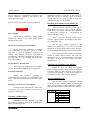
1
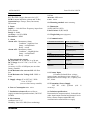
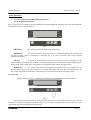
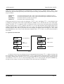
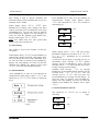
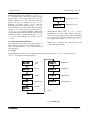
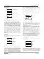
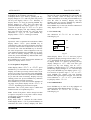
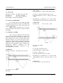
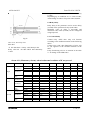
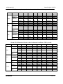
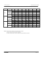
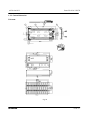
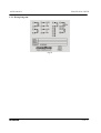
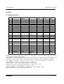
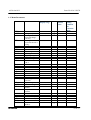
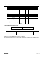
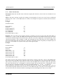
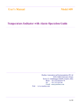
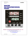
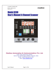
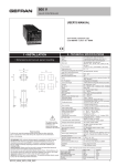
User’s Manual
Model 409-S RPM
RPM Indicator with Alarm Operation Guide
Masibus Automation and Instrumentation (P) Ltd.
B/30, GIDC Electronics Estate,
Sector-25, Gandhinagar-382044, Gujarat, India.
Phone : +91-79-23287275/79.
Fax
: +91-79-23287281.
E-mail : [email protected]
Web : www.masibus.com
1 of 33
m59A/om/101
Issue No:01B/110539
Contents
Forward
Notice
Trademarks
Revision
Safety precautions
Handling Precautions for the Unit
Checking the content of the package
Symbols used in this manual
4
4
4
4
4
5
5
6
RPM Indicator Overview
6
Technical details
1. Display
2. Input
3. Alarm Control
4. Transmission output
5. Supply Voltage
6. Power Consumption
7. Insulation resistance
8. Environment
9. Case
10. Mounting method
11. Dimension
12. Weight
13. Communication
14. Safety Standard
15. Contact Input
16. Transmitter Power Supply
7
7
7
7
7
7
7
7
7
7
7
7
7
7
7
7
7
Basic Operation
8
1. Overview of display switching and operation keys
1.1. Keyboard and operation
1.2. Password
1.3. Operation in main menu
1.4. Zero & Span setting
1.5. Slots setting
1.6. Retransmission
1.6.1. Retransmission voltage
1.6.2. Retransmission Current
1.6.3. Retransmission calibration
1.7. Alarm
1.7.1. Alarm type
1.7.2. Select
1.7.3. Latch
1.7.4. Hysteresis
1.7.5. Set point 1/ Set point 2
1.7.6. Relay delay
1.7.7. Control relay
1.7.8. Relay Delay
8
8
9
10
10
10
10
10
10
11
11
12
12
12
13
13
13
13
13
masibus
2 of 33
m59A/om/101
1.8. Communication
1.8.1. Serial Number
1.8.2. Baud rate
Calibration Procedure
1.1 Calibration for Retransmission
Alarm Operation
1.1. Set point type
1.2. Status of ALARM/TRIP
1.3. Latching of Alarm
1.4. HH Logic
1.5. HL Logic
1.6. LL Logic
1.7. Open sensor UP Scale/DOWN Scale
1.8. Relay Delay
1.9. Control Relay
Installation and Wiring
1.1. Installation Location
1.2. Wiring
1.2.1. Wiring Precautions
1.2.2. Cutout Dimensions
1.2.3. Wiring diagram
Parameter
1.1. Modbus Parameters
1.2. Menu Parameters
1.3. Retransmission output during OvER
1.4. Used Modbus functions descriptions
1.4.1. Read coil status (01)
1.4.2. Read Input status (02)
1.4.3. Read Holding register(03)
1.4.4. Read Input register(04)
1.4.5. Force single coil (05)
1.4.6. Preset Multiple Registers (16)
1.5. Exception responses for Modbus
masibus
Issue No:01B/110539
13
14
14
15
15
16
16
16
16
16
16
16
17
17
17
20
20
21
21
22
23
24
24
25
26
27
27
28
28
29
30
30
31
3 of 33
m59A/om/101
Issue No: 01A/110539
Foreword
Thank you for purchasing 59A series
RPM Indicator. This manual describes the basic
functions and operation methods of 59A.Please
read through this user’s manual carefully before
using the product.
“Handle With Care” (This symbol is
attached to the part(s) of the product to indicate
that the user’s manual should be referred to in
order to protect the operator and the instrument
from harm.)
Notice
The contents of this manual are subject to
change without notice as a result of continuing
improvements to the instrument’s performance
and functions.
Every effort has been made to ensure
accuracy in the preparation of this manual.
Should any errors or omissions come to your
attention, however, please inform MASIBUS
Sales office or sales representative.
Under no circumstances may the contents
of this manual, in part or in whole, be transcribed
or copied without our permission.
Trademarks
Our product names or brand names
mentioned in this manual are the trademarks or
registered trademarks of Masibus Automation and
Instrumentation (P) Ltd. (herein after referred to
as MASIBUS).
Adobe, Acrobat, and Postscript are either
registered trademarks or trademarks of Adobe
Systems Incorporated.
All other product names mentioned in this
user's manual are trademarks or registered
trademarks of their respective companies.
Safety Precaution
The following symbols are used in the
product and user’s manuals to indicate safety
precautions
masibus
Protective grounding terminal.
Functional grounding terminal (Do not
use this terminal as a protective grounding
terminal.)
Alternating Current.
Direct Current.
In order to protect the system
controlled by this product and the product itself,
and to ensure safe operation, observe the safety
precautions described in this user’s manual. Use
of the instrument in a manner not prescribed
herein may compromise the product's functions
and the protection features inherent in the device.
We assume no liability for safety, or
responsibility for the product's quality,
performance or functionality should users fail to
observe these instructions when operating the
product.
Be sure to use the spare parts approved
by MASIBUS when replacing parts or
consumables.
This product is not designed or
manufactured to be used in critical applications that
directly affect or threaten human lives. Such
applications include nuclear power equipment,
devices using radioactivity, railway facilities,
aviation equipment, air navigation facilities,
4 of 33
m59A/om/101
aviation facilities, and medical equipment. If so
used, it is the user’s responsibility to include in the
system additional equipment and devices that
ensure personnel safety.
Issue No: 01A/110539
The product is provided on an "as is" basis.
MASIBUS assumes no liability to any person or
entity for any loss or damage, direct or indirect,
arising from the use of the product or from any
unpredictable defect of the product.
Modification of the product is strictly prohibited.
Handling Precautions for the Main Unit
WARNING
WARNING
Power Supply
Ensure that the instrument’s supply voltage
matches the voltage of the power supply before
turning ON the power.
Do Not Use in an Explosive Atmosphere
Do not operate the instrument in locations
with combustible or explosive gases or steam.
Operation in such environments constitutes an
extreme safety hazard. Use of the instrument in
environments with high concentrations of corrosive
gas (H2S, Sox, etc.) for extended periods of time
may cause a failure.
Do Not Remove Internal Unit
The internal unit should not be removed by
anyone other than MASIBUS's service personnel.
External Connection
Ensure that protective grounding is
connected before connecting the instrument to the
device under measurement or to an external control
circuit.
Damage to the Protective Construction
Operation of the instrument in a manner not
specified in this user’s manual may damage its
protective construction.
Warning and Disclaimer
MASIBUS makes no warranties regarding
the product except those stated in the WARRANTY
that is provided separately.
masibus
The instrument comprises many plastic
components. To clean it, wipe it with a soft, dry
cloth. Do not use organic solvents such as benzene
or thinner for cleaning, as
discoloration or
deformation may result.
Keep electrically charged objects away
from the signal terminals. Not doing so may cause
the instrument to fail.
Do not apply volatile chemicals to the
display area, operation keys, etc. Do not leave the
instrument in contact with rubber or PVC products
for extended periods. Doing so may result in failure.
If the equipment emits smoke or abnormal
smells or makes unusual noises, turn OFF the
instrument’s power switch immediately and unplug
the device. In such an event, contact your sales
representative.
Checking the Contents of the Package
Unpack the box and check the contents
before using the product. If the product is different
from that which you have ordered, if any parts or
accessories are missing, or if the product appears to
be damaged, contact your sales representative.
Model and Suffix code
The 59A main unit has a nameplate affixed
to the top of the terminals. Check the model and
suffix codes inscribed on the nameplate to confirm
that the product received is that which was ordered.
Model
409 - RPM
Retransmission o/p
X
1
4 – 20 mA
2
0 – 20 mA
3
1 – 5 VDC
4
0 – 5 V DC
5
0 – 10V DC
Table 1
5 of 33
m59A/om/101
Issue No: 01A/110539
Accessories
The product is provided with the following
accessories according to the model and suffix codes
(see the table below). Check that none of them are
missing or damaged.
damage to the instrument, and signifies that the user
must refer to the user’s manual for special
instructions. The same symbol is used in the user’s
manual on pages that the user needs to refer to,
together with the term “WARNING” or
“CAUTION.”
WARNING
No
Item
name
Part
number
Qty
Remarks
Calls attention to actions or conditions that
could cause serious or fatal injury to the user, and
indicates precautions that should be taken to
prevent such occurrences.
Table 2
Symbols Used in This Manual
This symbol is used on the instrument. It
indicates the possibility of injury to the user or
RPM Indicator Overview:
Model 409-RPM is a powerful micro-controller based RPM (revolutions per minute) indicator,
designed to accept frequency input and features two programmable set points with individual relays.
Model 409-RPM accepts frequency input from proxy sensor, and delivers high accurate readings,
typically ±0.015% RPM facilitates plant operator to use in any application. Model 409-RPM is easy to
operate and configuration is user friendly. The RPM Indicator has an internal power supply that can
provide +24V dc to the Proxy sensor.
masibus
6 of 33
m59A/om/101
Technical details
1. Display
PV: Red LED 5-digit, character size 0.56”.
LED for status indication (Alarm and Tx/Rx)
Operation keys: Escape, Enter, Increment,
Decrement.
2. Input
Input: 0 – 166.666 Hertz Frequency input from
Proxy Sensor
Range: 0-10000
Accuracy: ±0.015% RPM
Resolution: 1 RPM
Issue No: 01A/110539
9. Case
Material: ABS Plastic.
Color: Black.
10. Mounting method Panel mounting.
11. Dimension
96(W)*48(H)*112(D).
Panel Cutout: 92(W)*46(H)
12. Weight 260 grams (Approx.)
13. Communication
3. Alarm
Alarm AL1 - Momentary Alarm
Condition – high/low/vlow
Lamp – on/flash/latch
Relay – on/off
Alarm AL2 - Momentary Alarm
Condition – vhigh/high/low
Lamp – on/flash/latch
Relay – on/off
4. Re transmission output
DC Current: 0 to 20 mA DC, 4 to 20 mA
DC Voltage: 0 to 10 V DC, 0 to 5V DC, 1 to
5V DC.
Accuracy ±0.25% of full Span (one at a time
factory settable).
Load Resistance for current O/P: 600 Ω or
less
Load Resistance for Voltage O/P: 2 KΩ or
more
5. Supply voltage 85 to 265V AC, 50Hz.
18 to 36 V DC .
(one at a time factory settable).
6. Power Consumption Max. 10VA
7. Insulation resistance Between Power
supply terminal and ground terminal, 500V DC
50 MΩ.
8. Environment
Ambient: 0 to 55 ºC.
Humidity: 20 to 95% RH (Non-condensing).
masibus
Communication Interface
Communication method
Based on EIA RS-485.
Half-duplex communication
start
stop
synchronous.
Communication Speed
4800/9600/19200/38400bps
selectable by key.
Parity
Communication Protocol
None.
Modbus RTU.
Connectable number of
unit
Max.32 unit
computer.
Communication
detection
CRC check
error
per
host
Table 4.
14. Contact Input
1-Channel (Isolated) Non- voltage
contact input, maximum reverse voltage 6V,
Maximum Forward voltage 50V, Capacity 24V
DC, 10mA
15. Transmitter Power Supply
24V DC ±10% @26mA
accuracy)
(±10
%
16. Isolation specification:
Retransmission output terminal - Isolated from
other input/output terminal and internal circuit
Relay contact output terminal/RS-485
communication terminal/Power supply
7 of 33
m59A/om/101
Issue No: 01A/110539
Basic Operation
1. Overview of Display Switching and Operation keys
1.1. Keyboard and Operation
There are four keys for operation of the instruments. For understanding the operation first of all understand the
functionality of keys as shown in Fig.1.
AL 1
Tx
AL 2
Rx
masibus
409
MENU
ENT
UP
DOWN
Fig.1.
MENU key
: It is used to come out from the main or sub menu.
ENTER key
: It is used to select the desired parameter in various operating mode. After setting
the data to proper value, by increment or decrement key, it is used to enter the value of the selected
parameter in memory.
UP key
: It is used to increment the parameter for selection. Value of parameter can be
incremented by pressing this key. If the key is pressed continuously for more than 10 counts change, the rate
of increment will be made faster. This facility is to allow faster data change for higher values.
DOWN key
: It is used to decrement the parameter for selection. Value of parameter can be
decremented by pressing this key. If the key is pressed continuously for more than 10 counts change, the
rate of decrement will be made faster. This facility is to allow faster data change for higher values.
1.2. Password
Display indicates “PASS” on display by pressing key (UP & DOWN keys simultaneously).
Fig.2.
This is User settable password. It can be any value between 1 to 9999. This password is to be entered
each time user needs to change any parameter/value. User can set his own password as per his choice to avoid
excess of the previous stored data in the instrument.
masibus
8 of 33
m59A/om/101
Issue No: 01A/110539
When user presses UP & DOWN keys simultaneously as shown in Fig. 2. Display shows “PASS”; press
ENTER key and entered the previously stored value of password using UP, DOWN keys. The functioning of the
keys is as follow.
DOWN key
UP key
ENTER key
MENU key
: Is used to decrement the value. Value can be decremented up to minimum value 0.
: Is used to increment the value. Value can be incremented up to maximum value 9999.
: Is used to store the set value as password.
: Is used to come out from the menu.
If password entered is of correct value it will display “CHANG”, else it will display”FAIL”. If user doesn’t want
to change the previously stored value of password press “MENU” key it will take the user in to main menu.
Display will show “Zero” in the main menu. To change the values of previously stored password press ENTER
key when display shows “CHANG”. Display will show “0”. User can increment the value of digit using UP key
and decrement the digit using DOWN key. Once user set the value and presses the ENTER key display stops
blinking indicates that value of password has been changed and display shows message”OK” now, again
pressing MENU key user will be in the main menu. Display shows “Zero” that is very first menu message in
main menu.
1.3. Operation in main menu
Zero
Zero adjustment
rEtrN
Retransmission
output
SpaN
Span
adjustment
ALARM
Alarm control
SLotS
Number of slots
ComuN
Communication
Fig. 3.
As shown in above Fig.3 by pressing UP key in incremental (from message “Zero”) display message will
be as indicated by arrow. The last message will be “ComuN” and even after user presses UP key, message will
not change. Similarly from message “ComuN” by pressing DOWN key in incremental display message will be
reversed from “ComuN” to “Zero”. The last message will be “Zero” and even after user presses DOWN key,
message will not change. To enter in to the submenu from main menu press ENTER key.
masibus
9 of 33
m59A/om/101
Issue No: 01A/110539
1.4. Zero & Span setting
1.6.1. Retransmission voltage
This setting is used to specify minimum and
maximum range of factory default value of zero is 0
and span value is 10000.
Press ENTER key to enter in to the submenu of
retransmission voltage when display shows
“retv”.The submenus of “retv” are as shown in
following Fig.5.
When display shows “zero”/ “sPAN” press
ENTER key to change value. Display will show
value of zero/span, user can change the value using
UP/DOWN keys. To store the value in memory
press ENTER key, display will stop flashing. To
come out from the submenu press MENU key,
display will be again “zero”/ “sPAN”.
Note: User cannot enter zero value greater than
span or span value less than zero.
1.5. Slots setting
This setting is used to the number of slots per
revolution.
When display shows “SLotS” press ENTER key to
change value. Display will show value from 1 to 60,
user can change the value using UP/DOWN keys.
To store the value in memory press ENTER key,
display will stop flashing. To come out from the
submenu press MENU key, display will be again
“SLotS”. User can enter maximum 60 slots.
1.6. Retransmission
Press ENTER key to enter in to the submenu of
retransmission when display shows “RETRN”.The
submenus of “RETRN” are as shown in following
Fig.4.
0-10V
0-10V
0-5v
0-5V
1-5v
1-5V
Fig.5
When display shows “retv” and user presses
ENTER key display can be either of “0-10v”,”05v”, or “1-5v” depending up on previously
selected logic.
As shown in above Fig.8 by pressing UP key in
incremental (from message “0-10v”) display
message will be as indicated by arrow. The last
message will be “1-5v” and even after user presses
UP key, message will not change.
Similarly from message “1-5v” by pressing
DOWN key in incremental display message will be
reversed from “1-5v” to “0-10v”. The last
message will be “0-10v” and even after user
presses DOWN key, message will not change. To
store the value in memory press ENTER key,
display will stop flashing. To come out from the
submenu press MENU key, display will be again
“retv”.
1.6.2. Retransmission Current
The submenus of “retmA” are as shown in
following
Fig.6.
Fig.4
0-20
0-20
4-20
4-20
Fig.6.
masibus
10 of 33
m59A/om/101
Issue No: 01A/110539
When display shows “retma” and user presses
ENTER key display can be either of “0-20” or “420” depending up on previously selected logic.If
display shows “0-20” then by pressing UP key
display changes to “4-20” and even after user
presses UP key last display will be “4-20”.
Similarly, if display shows “4-20” then by
pressing DOWN key display changes to “0-20”
and even after user presses DOWN key last display
will be “0-20”. For selection of specific logic i.e.
“0-20” or “4-20” press ENTER key, display will
stop flashing which indicates that the logic has been
selected. To come out from submenus i.e. “0-20”
or “4-20” press MENU key display will be
“retma”.
1.6.3. Retransmission calibration
Press ENTER key to enter in to the submenu of
retransmission calibration when display shows “r
CAL”. The submenus of “r CAL” are as shown in
following Fig.7.
1.7. Alarm
rtn S
Retransmission span
rtn Z
Retransmission zero
Fig.7
When display shows “rtN S”/ “rtN Z” press
ENTER key to change value. Display will show
value, user can change the value using UP/DOWN
keys. To come out from the submenu press MENU
key, display will be again “rtn S”/ “rtn Z”.
Note: This is common for calibration of both
voltage and current output.
Press ENTER key to enter in to the submenu of alarm when display shows “ALARM”. The submenus of
“ALARM” are as shown in following Fig.8.
ATYPE
Alarm
Type
SETP1
Setpoint 1
SELCT
Select
SETP2
Setpoint 2
LATCh
Latch
rldly
Relay delay
hyst
Hysteresis
CTRLY
Control relay
SENSR
Sensor
Fig.8
1.7.1. Alarm type
masibus
11 of 33
m59A/om/101
Issue No: 01A/110539
The submenus of “ATYPE” are as shown in
following Fig.9.
hh
High-High logic
hl
High-Low logic
ll
Low-Low logic
Fig.9
When display shows “ATYPE” and user presses
ENTER key display can be either of “hh”,”hl”, or
“ll” depending up on previously selected logic.
As shown in above Fig.12 by pressing UP key in
hh”)
incremental (from message “hh
hh display message
will be as indicated by arrow. The last message will
be “LL” and even after user presses UP key,
message will not change. Similarly from message
“LL” by pressing DOWN key in incremental
display message will be reversed from “ll” to
“hh”. The last message will be “hh” and even after
user presses DOWN key, message will not change.
To store the value in memory press ENTER key,
display will stop flashing. To come out from the
submenu press MENU key, display will be again
“ATYPE”.
1.7.2. Select
The submenus of “SELCT” are as shown in
following Fig.10.
AL1
Alarm 1
AL2
Alarm 2
Fig.10
As shown in Fig.10 by pressing UP key in
incremental (from message “AL1”) display message
will be as indicated by arrow. The last message will
be “AL2” and even after user presses UP key,
message will not change. Similarly from message
“AL2” by pressing DOWN key in incremental
masibus
display message will be reversed from “AL2” to
“AL1”. The last message will be “AL1” and even
after user presses DOWN key, message will not
change. To come out from the submenu press
MENU key, display will be again “SELCT”.
Submenus of “AL1” and “AL2” are as under. This
is used to select the operation of individual relays.
ALARM
Alarm logic
TRIP
Trip logic
Fig.11
When display shows either “AL1” or “AL2” and
user presses ENTER key display message will be
either “ALARM” or “TRIP” depending up on
previously selected logic.
If display shows “ALARM” then by pressing UP key
display changes to “TRIP” and even after user
presses UP key last display will be “TRIP”.
Similarly, if display shows “TRIP” then by
pressing DOWN key display changes to “ALARM”
and even after user presses DOWN key last display
will be “ALARM”. For selection of specific logic i.e.
“ALARM” or “TRIP” press ENTER key ,display
will stop flashing indicates that logic has been
selected. To come out from submenus i.e. “ALARM”
or “TRIP” press MENU key display will be “AL1”
or “AL2”, depending up on alarm type selected.
1.7.3. Latch
The submenus of “LatCh” are as shown in
following Fig12.
YES
Yes
No
No
Fig.12
This indicates that whether alarm is with latch
(“yes”) or without latch logic (“No”). When
display shows “LATCh” and user presses ENTER
12 of 33
m59A/om/101
key display message will be either “yes” or “No”
depending up on previously selected logic.
If display shows “yes” then by pressing UP key
display changes to “No” and even after user presses
UP key last display will be “No”. Similarly, if
display shows “No” then by pressing DOWN key
display changes to “YES” and even after user
presses DOWN key last display will be “YES”. For
selection of specific logic i.e. “YES” or “No” press
ENTER key ,display will stop flashing indicates
that logic has been selected. To come out from
submenus i.e. “YES” or “No” press MENU key
display will be “latCh”. alarm type selected.
Issue No: 01A/110539
previously entered value of delay .Use UP key to
increase the value and DOWN key to decrease the
value of delay. Value of delay can vary from
0(Min)-9999(Max) in second, press ENTER key to
store the value in memory. Display will stop
flashing when user presses ENTER key indicates
that value has been stored in memory.
Press MENU key to come out from the submenu of
delay, display will be “rlDly”.
1.7.7. Control relay
The submenus of “Ctrly” are as shown in
following Fig.14.
1.7.4. Hysteresis
Hysteresis value is common for both alarms. When
display shows “hyst” press ENTER key to
enter/alter the value of hysteresis.Display will show
previously entered value of hysteresis .Use UP key
to increase the value and DOWN key to decrease
the value of hysteresis. Value of hysteresis can vary
from 0(Min)-255(Max),press ENTER key to store
the value in memory. Display will stop flashing
when user presses ENTER key indicates that value
has been stored in memory.
Press MENU key to come out from the submenu of
hysteresis, display will be “hyst”.
1.7.5. Set point 1/ Set point 2
When display shows “setp1” or “setp2” press
ENTER key to enter/alter the value of set point.
Display will show previously entered value of set
point .Use UP key to increase the value and DOWN
key to decrease the value of set point. Press ENTER
key to store the value in memory. Display will stop
flashing when user presses ENTER key indicates
that value has been stored in memory.
Press MENU key to come out from the submenu of
set point 1/set point2, display will be “setp1” or
“setp2” depending up on selected set point .
Maximum value of set points may be 10000 and
minimum value of set points may be 0.
Note: Value of set point 1 will be always less than
or equal to set point 2 or set point 2 will be always
greater than or equal to set point 1.
1.7.6. Relay delay
Relay delay value is common for both alarms.
When display shows “rlDly” press ENTER key to
enter/alter the value of delay. Display will show
masibus
oN
ON
oFF
OFF
Fig.14
When display shows “Ctrly” and user presses
ENTER key display message will be either “oN” or
“oFF” depending up on previously selected logic.
If display shows “oN” then by pressing UP key
display changes to “oFF” and even after user
presses UP key last display will be “oFF”.
Similarly, if display shows “oFF” then by pressing
DOWN key display changes to “oN” and even after
user presses DOWN key last display will be “oN”.
For selection of specific logic i.e. “oN” or “oFF”
press ENTER key ,display will stop flashing
indicates that logic has been selected. To come out
from submenus i.e. “oN” or “oFF” press MENU
key display will be “Ctrly”.
1.8. Communication
Press ENTER key to enter in to the submenu of
communication when display shows “ComuN”.
The submenus of “CoMUN” are as shown in
following Fig.15.
13 of 33
m59A/om/101
Issue No: 01A/110539
SrSr-No
Serial Number
4800
4800
BAUD
Baud rate
9600
9600
19200
19200
38400
38400
Fig.15
When display shows “CoMUN” and user presses
ENTER key display message will be either “SRNo” or “BAUD”.
If display shows “SR-No” then by pressing UP key
display changes to “BAUD” and even after user
presses UP key last display will be “BAUD”.
Similarly, if display shows “BAUD” then by
pressing DOWN key display changes to “Sr-No”
and even after user presses DOWN key last display
will be “Sr-No”. For selection of specific menu i.e.
“Sr-No” or “BauD” press ENTER key, display
will show submenu of corresponding display. To
come out from submenus i.e. “Sr-No” or “BAUD”
press MENU key display will be “ComuN”.
1.8.1. Serial Number
This value is for slave ID /Node address selection.
When display shows “SR-No” press ENTER key to
enter/alter the value of serial number. Display will
show previously entered value of serial number
.Use UP key to increase the value and DOWN key
to decrease the value. Value of serial number can
vary from 1(Min)-247(Max), press ENTER key to
store the value in memory. Display will stop
flashing when user presses ENTER key; it indicates
that value has been stored in memory.
Press MENU key to come out from the submenu of
serial no, display will be “Sr-No”.
Fig.16
When display shows “BAUD” and user presses
ENTER key display can be either of
“4800”,”9600”, ”19200”, or “38400” depending
up on previously selected value.
As shown in Fig.19 by pressing UP key in
incremental (from message “4800
4800”)
display
4800
message will be as indicated by arrow. The last
message will be “38400” and even after user
presses UP key, message will not change. Similarly
from message “38400” by pressing DOWN key in
incremental display message will be reversed from
“38400” to “4800”. The last message will be
“4800” and even after user presses DOWN key,
message will not change. To store the value in
memory press ENTER key, display will stop
lashing. To come out from the submenu press
MENU key, display will be again “BAUD”.
1.8.2. Baud rate
This is used to select baud rate for communication.
The submenus for baud rate are as shown in
following Fig.16.
masibus
14 of 33
m59A/om/101
Issue No: 01A/110539
Calibration Procedure
1.1. Calibration for Retransmission.
The calibration in the instrument is using front panel keys only. Instrument can be calibrated even during
installed condition.
Calibration is carried out using following steps.
1) Enter in to calibration mode using front panel keys. Display indicates “RETRN” in 5-segment display.
2) Select type of output i.e.voltage or current output RET V or RET I then and then it will allow you to enter
for calibration of zero and span.
3) After selecting type of output Press UP, DOWN key to get a prompt “RCAL” and press ENTER key to
enter in to calibration.
3) Display indicates “RETZ“for zero calibration;”RETS” for span calibration User can enter in to zero/span
calibration using UP, DOWN keys (applicable for both voltage/current output).
4) To perform zero calibration press ENTER key when display shows “RETZ“.when user presses ENTER
key display will be previously stored counts for voltage output/current output. Retransmission output will be
nearly equal to 0 V/0mA depending up on type of selection. If output differs from 0V/0mA vary counts to
get desire output.
5) Irrespective of value of count try to obtain 0V/0mA at the output and press ENTER key to store
calibrated value in memory.
Repeat the above same steps for span calibration here, desired voltage output is 10V and current output is
20mA.
Note: calibration for voltage output is required to do in 0-10V range and for current output its 0-20mA range,
which incorporates other ranges also. Incase of current output specially to calibrate for zero side vary count in
display such that output is greater then zero mA and then bring it down by varying counts it to zero mA.
masibus
15 of 33
m59A/om/101
Alarm Operation
1.1. Alarm type
HH-high, very high. AL1-high, AL2-very high
HL-high, low
AL1-low, AL2-high.
LL-low, low
AL1-very low, AL2-low.
This setting is common for all groups.
1.2. Status of ALARM/TRIP
It will toggle between ALARM and TRIP
depending up on selection in menu. ALARM mode
is further subdivided into Alarm with Latch and
Alarm without Latch.
TRIP is useful when the relay is used for
tripping the plant or device and it is not to be started
once again.
Issue No: 01A/110539
If PV>SP1 but, less then SP2 => Relay 1- ON,
Relay 2-OFF.
If PV<SP1-Hyst1 => Relay 1-OFF, Relay 2-OFF.
PV>SP2 => Relay1 and Relay2 both are ON.
If PV<SP2-Hyst2 but, >SP1 => Relay 1-ON, Relay
2-OFF.
Depending up on condition set i.e. Latch Yes/No,
Acknowledge Yes/No or Trip refer table7,8,9,&10.
1.5.HL Logic
HL-high, low
AL1-low, AL2- high.
1.3. Latching of ALARM
This is used for latching of discrete LEDs
and relay status when alarm limit is crossed. This
option will keep discrete LEDs/Relay latched even
after channel has come to normal status until
ENTER (ACK) key is pressed. This option can be
changed to YES or NO for enabling or disabling
respectively. When configurations of Alarms are of
TRIP type, these parameters will be skipped from
display. The
different
conditions
for
the
ALARM/TRIP have been mentioned in the
following table7, 8, 9, &10.
1.4.HH Logic
HH-high, very high. AL1-high, AL2-very high
Fig.22
AL1-low, AL2- High
SP2>SP1
If PV>SP2 then Relay 2-ON.
If PV<SP2-Hyst2 => Relay 2-OFF.
PV<SP1 => Relay1 ON.
If PV>SP1+Hyst1 then. Relay 1-OFF.
Depending up on condition set i.e. Latch Yes/No,
Acknowledge Yes/No or Trip refer table7, 8, 9 &
10.
1.6.LL Logic
LL-low, low AL1-very low, AL2-low.
Fig.21
AL1-High, AL2-Very High
SP2>SP1
masibus
16 of 33
m59A/om/101
Issue No: 01A/110539
Relay 2-ON till PV>SP2+HYS2 after that Relay
2- OFF.
Depending up on condition set i.e. Latch Yes/No,
Acknowledge Yes/No or Trip refer table7,8,9&10.
1.8 Relay Delay
Relay delay is the parameter used to set the delay
(second) in the operation of relays (both 1&2).
Minimum value of delay is 0(second) and
maximum value 9999 (second) can be configured
using keyboard.
1.9. Control Relay
Fig.23
AL1-Low, AL2-Very Low
SP2>SP1
If PV<SP1 then => Relay 1-ON, Relay 2-ON.
Relay 1-ON till PV>SP1+HYS1 after that Relay
1-OFF.
Control relay “OFF” then relay will function
according to the condition mention in the following
tables.
Control relay “ON” then functioning of relay will
be just opposite to the condition mention in the
table.
Lamp functioning will be as mention in the table
i.e. no change in the LED status.
Alarm AL1 (Momentary Alarm): when in abnormal condition ACK not pressed.
Condition
High
Low
VLOW
Normal
Abnormal
UP
DOWN
ACK**
Normal*
Alarm
Latch(Yes)
Alarm
Latch(No)
LAMP
RELAY
LAMP
RELAY
OFF
OFF
OFF
OFF
FLASH
ON
FLASH
ON
FLASH
ON
FLASH
ON
OFF
OFF
OFF
OFF
FLASH
OFF
OFF
OFF
ACK
***
OFF
OFF
OFF
OFF
Trip
Alarm
Latch(Yes)
Alarm
Latch(No)
LAMP
RELAY
LAMP
RELAY
LAMP
RELAY
OFF
OFF
OFF
OFF
OFF
OFF
FLASH
ON
FLASH
ON
FLASH
ON
OFF
OFF
OFF
OFF
OFF
OFF
OFF
OFF
FLASH
ON
FLASH
ON
FLASH
ON
FLASH
OFF
OFF
OFF
OFF
OFF
OFF
OFF
OFF
OFF
Trip
Alarm
Latch(Yes)
Alarm
Latch(No)
LAMP
RELAY
LAMP
RELAY
LAMP
RELAY
OFF
OFF
OFF
OFF
OFF
OFF
FLASH
ON
FLASH
ON
FLASH
ON
OFF
OFF
OFF
OFF
OFF
OFF
OFF
OFF
FLASH
ON
FLASH
ON
FLASH
ON
FLASH
OFF
OFF
OFF
OFF
OFF
OFF
OFF
OFF
OFF
Trip
LAMP
RELAY
OFF
OFF
FLASH
ON
OFF
OFF
OFF
OFF
FLASH
ON
OFF
OFF
Table 7.
masibus
17 of 33
m59A/om/101
Issue No: 01A/110539
Alarm AL2 (Momentary Alarm): when in abnormal condition ACK not pressed.
Condition
VHigh
High
LOW
Normal
Abnormal
UP
DOWN
ACK**
Normal*
Alarm
Latch(Yes)
Alarm
Latch(No)
LAMP
RELAY
LAMP
RELAY
OFF
OFF
OFF
OFF
FLASH
ON
FLASH
ON
FLASH
ON
FLASH
ON
OFF
OFF
OFF
OFF
FLASH
OFF
OFF
OFF
ACK
***
OFF
OFF
OFF
OFF
Trip
Alarm
Latch(Yes)
Alarm
Latch(No)
LAMP
RELAY
LAMP
RELAY
LAMP
RELAY
OFF
OFF
OFF
OFF
OFF
OFF
FLASH
ON
FLASH
ON
FLASH
ON
OFF
OFF
FLASH
ON
FLASH
ON
OFF
OFF
OFF
OFF
OFF
OFF
FLASH
ON
FLASH
OFF
OFF
OFF
OFF
OFF
OFF
OFF
OFF
OFF
Trip
Alarm
Latch(Yes)
Alarm
Latch(No)
LAMP
RELAY
LAMP
RELAY
LAMP
RELAY
OFF
OFF
OFF
OFF
OFF
OFF
FLASH
ON
FLASH
ON
FLASH
ON
OFF
OFF
OFF
OFF
OFF
OFF
OFF
OFF
FLASH
ON
FLASH
ON
FLASH
ON
FLASH
OFF
OFF
OFF
OFF
OFF
OFF
OFF
OFF
OFF
Trip
LAMP
RELAY
OFF
OFF
FLASH
ON
OFF
OFF
OFF
OFF
FLASH
ON
OFF
OFF
Table 8
Alarm AL1 (Maintained Alarm): when in abnormal condition ACK is pressed.
Condition
High
Low
VLOW
Normal
Abnormal
UP
DOWN
ACK**
Normal*
Alarm
Latch(Yes)
Alarm
Latch(No)
LAMP
RELAY
LAMP
RELAY
OFF
OFF
OFF
OFF
FLASH
ON
FLASH
ON
FLASH
ON
FLASH
ON
OFF
OFF
OFF
OFF
STEADY
ON
STEADY
OFF
STEADY
OFF
OFF
OFF
ACK
***
OFF
OFF
OFF
OFF
Trip
Alarm
Latch(Yes)
Alarm
Latch(No)
LAMP
RELAY
LAMP
RELAY
LAMP
RELAY
OFF
OFF
OFF
OFF
OFF
OFF
FLASH
ON
FLASH
ON
FLASH
ON
OFF
OFF
OFF
OFF
OFF
OFF
OFF
OFF
FLASH
ON
FLASH
ON
STEADY
ON
STEADY
ON
STEADY
OFF
STEADY
ON
STEADY
OFF
OFF
OFF
OFF
OFF
OFF
OFF
OFF
OFF
Trip
Alarm
Latch(Yes)
Alarm
Latch(No)
LAMP
RELAY
LAMP
RELAY
LAMP
RELAY
OFF
OFF
OFF
OFF
OFF
OFF
FLASH
ON
FLASH
ON
FLASH
ON
OFF
OFF
OFF
OFF
OFF
OFF
OFF
OFF
FLASH
ON
FLASH
ON
STEADY
ON
STEADY
ON
STEADY
OFF
STEADY
ON
STEADY
OFF
OFF
OFF
OFF
OFF
OFF
OFF
OFF
OFF
Trip
LAMP
RELAY
OFF
OFF
FLASH
ON
OFF
OFF
OFF
OFF
STEADY
ON
STEADY
ON
OFF
OFF
Table 9
masibus
18 of 33
m59A/om/101
Issue No: 01A/110539
Alarm AL2 (Maintained Alarm): when in abnormal condition ACK is pressed.
Condition
VHigh
High
LOW
Normal
Abnormal
UP
DOWN
ACK**
Normal*
Alarm
Latch(Yes)
Alarm
Latch(No)
LAMP
RELAY
LAMP
RELAY
OFF
OFF
OFF
OFF
FLASH
ON
FLASH
ON
FLASH
ON
FLASH
ON
OFF
OFF
OFF
OFF
STEADY
ON
STEADY
OFF
STEADY
OFF
OFF
OFF
ACK
***
OFF
OFF
OFF
OFF
Trip
Alarm
Latch(Yes)
Alarm
Latch(No)
LAMP
RELAY
LAMP
RELAY
LAMP
RELAY
OFF
OFF
OFF
OFF
OFF
OFF
FLASH
ON
FLASH
ON
FLASH
ON
OFF
OFF
FLASH
ON
FLASH
ON
OFF
OFF
OFF
OFF
OFF
OFF
STEADY
ON
STEADY
ON
STEADY
OFF
STEADY
ON
STEADY
OFF
OFF
OFF
OFF
OFF
OFF
OFF
OFF
OFF
Trip
Alarm
Latch(Yes)
Alarm
Latch(No)
LAMP
RELAY
LAMP
RELAY
LAMP
RELAY
OFF
OFF
OFF
OFF
OFF
OFF
FLASH
ON
FLASH
ON
FLASH
ON
OFF
OFF
OFF
OFF
OFF
OFF
OFF
OFF
FLASH
ON
FLASH
ON
STEADY
ON
STEADY
ON
STEADY
OFF
STEADY
ON
STEADY
OFF
OFF
OFF
OFF
OFF
OFF
OFF
OFF
OFF
Trip
LAMP
RELAY
OFF
OFF
FLASH
ON
OFF
OFF
OFF
OFF
STEADY
ON
STEADY
ON
OFF
OFF
Table 10
Notes: *means normal condition after abnormal has occurred.
**means ACK pressed in abnormal condition.
***means ACK pressed in normal condition after abnormal has occurred.
masibus
19 of 33
m59A/om/101
Issue No: 01A/110539
Installation and Wiring.
1. 1.Installation Location
WARNING
1) Devices must be installed by professionally trained personnel.
2) Install devices according to NEC (National Electrical Code: ANSI/NFPA-70).
The instrument should be installed in indoor locations meeting the following conditions:
• Instrumented panel
This instrument is designed to be mounted in an instrumented panel. Mount the instrument in a location where
its terminals will not inadvertently be touched.
• Well ventilated locations
Mount the instrument in well ventilated locations to prevent the instrument’s internal temperature from rising.
To mount multiple indicating controllers, see the external dimensions/panel cutout dimensions which follow. If
mounting other instruments adjacent to the instrument, comply with these panel cutout dimensions to provide
sufficient clearance between the instruments.
• Horizontal location
Mount the instrument horizontally and ensure that it is level, with no inclination to the right or left.
Note: If the instrument is moved from a location with low temperature and low humidity to a place with high
temperature and high humidity, or if the temperature changes rapidly, condensation will result. To avoid such a
situation, leave the instrument in the new environment under ambient conditions for more than 1 hour prior to
using it.
Do not mount the instrument in the following locations:
• Outdoors Locations subject to direct sunlight or close to a heater
Install the instrument in a location with stable temperatures that remain close to an average temperature of 23°C.
Do not mount it in locations subject to direct sunlight or close to a heater. Doing so adversely affects the internal
unit.
• Locations with substantial amounts of oily fumes, steam, dust, or corrosive gases
The presence of oily fumes, steam, dust, or corrosive gases adversely affects the instrument. Do not mount the
instrument in locations subject to any of these substances.
• Areas near electromagnetic field generating sources
Do not place magnets or tools that generate magnetism near the instrument. If the instrument is used in locations
close to a strong electromagnetic field generating source, the magnetic field may cause measurement errors.
• Locations where the display is difficult to see
Mount the instrument in a location where it can be seen as much as possible from the front.
masibus
20 of 33
m59A/om/101
Issue No: 01A/110539
• Areas close to flammable articles
Absolutely do not place the instrument directly on flammable surfaces. If such a circumstance is unavoidable
and the instrument must be placed close to a flammable item, provide a shield for it made of 1.43 mm thick
plated steel or 1.6 mm thick unplated steel with a space of at least 150 mm between it and the instrument on the
top, bottom and sides.
• Areas subject to being splashed with water
1.2. Wiring
1.2.1 Wiring Precautions
WARNING
1) Be sure to turn OFF the power supply before wiring to avoid an electric shock. Use a tester or similar device
to ensure that no power is being supplied to a cable to be connected.
2) As a safety measure, always install a circuit breaker (an IEC 60947-compatible product, 5 A, 100 V or 220 V
AC) in an easily accessible location near the instrument. Moreover, provide indication that the switch is a device
for turning off the power to the instrument.
3) Wiring work must be carried out by a person with basic electrical knowledge and practical experience.
WARNING
CAUTION
1) Provide electricity from a single-phase power supply. If the power is noisy, install an isolation transformer on
the primary side, and use a line filter on the secondary side. When measures against noise are taken, do not
install the primary and secondary power cables close to each other.
2) If there is a risk of external lightning surges, use a lightning arrester, etc.
masibus
21 of 33
m59A/om/101
Issue No: 01A/110539
1.2.2. Cutout Dimension
Unit:mm.
Fig.24
masibus
22 of 33
m59A/om/101
Issue No: 01A/110539
1.2.3. Wiring Diagram.
Fig.25
masibus
23 of 33
m59A/om/101
Issue No: 01A/110539
Parameter
1.1. Modbus Parameters.
Sr.No Parameter
1
2
3
4
5
6
7
8
9
10
11
*Relay status1
*Relay status2
*Alarm status1
*Alarm status2
Rpm
Zero display
Span display
Set point 1
Set point 2
Relay delay
Slots
Absolute
address
1
2
1001
1002
30001
40001
40002
40003
40004
40005
40006
12
13
14
15
Unused
Unused
Hysteresis
Serial number
40007
40008
40009
40010
16
17
*Baud rate
*Alarm logic
type
*Alarm 1
*Alarm 2
*Alarm Latch
* Alarm sensor
*Relay control
Password
40011
40012
18
19
20
21
22
23
Type
Bit
Bit
Bit
Bit
Integer
Integer
Integer
Integer
Integer
Integer
Unsigned
Integer
Unsigned char
Unsigned
Char
Unsigned char
Unsigned char
Minimum
value
0
0
0
0
Maximum
Value
1
1
1
1
0
1
9999
60
Access
Type
R/W
R
R
R
R
R/W
R/W
R/W
R/W
R/W
R/W
0
1
255
247
R/W
R/W
0
0
3
2
R/W
R/W
Unsigned char 0
1
R/W
Unsigned char 0
1
R/W
Unsigned char 0
1
R/W
Unsigned char 0
1
R/W
Unsigned char 0
1
R/W
Unsigned
1
9999
R/W
integer
Table 11
*Relay status1, *Relay status2 it gives status of LED. Relay status1 can be used to acknowledge using function
code-5.Address 3-16 for future use only.
*Alarm status1, *Alarm status2 gives status of abnormal condition only. Address 1003-1016 for future use only.
*Input type: 0 = Etc,1 = Jtc,2 = Ktc,3 = Ttc,4 = Btc,5 = Rtc,6 = Stc,7= pt-100, 8 = 0-400Ω,9 = 0-6000Ω,
10 = ±10V,11 = 0-10V,12 = 0-5V,13 = 1-5V,14 = 0-2V,15 = 0.4-2V,16 = -10-20mV,17 = ±75mV,18 = 075mV;*Baud rate: 0 = 4800, 1 = 9600, 2 = 19200, 3 = 38400.
*Alarm Latch: 0 = YES, 1 = NO;* Alarm sensor: 0 =UP, 1=DOWN.
*Relay control: 0 = ON, 1=OFF.*Alarm logic type: 0 = HH, 1 = HL, 2 = LL.
*Alarm 1: 0 = Alarm, 1 = Trip.*Alarm 2: 0 = Alarm, 1 = Trip.
Values when OPEN :– 32766, UNDER: – 32768, OVER: – 32767, doPEN: -32765.
*Decimal point: 4=0, 3= .0, 2=.00, 1=.000, 0=.0000
masibus
40013
40014
40015
40016
40017
40018
24 of 33
m59A/om/101
Issue No: 01A/110539
1.2. Menu Parameters
Parameter
Name
Setting and
Display range
Unit
pass
chaNg
ok
Pass word
Change of password
Message indicates
password change
correctly
Message indicates
password entered is
wrong.
Number of slots
Zero enter
Span enter
Alarm Logic
Alarm type
High-High logic
High-Low logic
Low-Low logic
Selection for Alarm
1 & 2.
Alarm 1
Alarm 2
Alarm selection
Trip selection
Latch status
Latch Yes
Latch No
Hysteresis
Sensor logic
selection
Up scale logic
Down scale logic
Set point 1 for
Alarm 1
Set point 2 for
Alarm 2
Relay delay
Control relay logic
On control relay
OFF control relay
485-Communication
Serial number for
Modbus.
0001 – 9999
0001 – 9999
Engg.
Engg
FAIL
Slots
Zero
SpaN
Alarm
Atype
hh
hl
ll
selCt
Al1
Al2
Alarm
TrIp
Latch
yes
No
hyst
Sensr
Up
dowN
Setp1
Setp2
Rldly
ctrly
oN
off
Comun
Sr-No
masibus
Factory
default
value
Undefined
Undefined
Display and
setting
condition
for
controller
mode
R/W
R/W
R
R
1-60
Slots
RPM
RPM
0-255
RPM
1
0
10000
R/W
R/W
R/W
R/W
R/W
R/W
0-9999
second
R/W
1-247
Engg
R/W
25 of 33
m59A/om/101
Baud
4800
9600
19200
38400
Retrn
Ret v
0-10v
0-5v
1-5v
Ret mA
0-20
4-20
R cal
Rtn s
Rtn z
Issue No: 01A/110539
Baud rate selection
4800
9600
19200
38400
Retransmission
Retransmission
voltage
Output 0-10V
Output 0-5V
Output 1-5V
Retransmission
current
Output 0-20mA
Output 4-20mA
Retransmission
calibration
Retransmission span
Retransmission zero
R/W
R/W
R/W
R/W
R/W
Table 12
1.3. Retransmission output during OVER
0-20 mA O/P
4-20 mA O/P
UP Scale O/P DW Scale O/P UP Scale O/P DW Scale O/P
21.00
0.0
20.8
3.2
Table 13-A
UP Scale
O/P
10.50
0-10 V O/P
0-5 V O/P
1-5 V O/P
DW Scale O/P UP Scale O/P DW Scale O/P UP Scale O/P DW Scale O/P
0.0
5.25
0.0
5.20
0.80
Table 13-B
OVER will be displayed when value is beyond 5% of span-zero.
Above mention value in the table will come only after calibration for specific o/p type i.e. Voltage/Current.
masibus
26 of 33
m59A/om/101
Issue No: 01A/110539
1.4. Used Modbus function descriptions.
1.4.1
Read coil status (01).
Description :Reads the ON/OFF status of discrete outputs (0X references, coils) in the slave. Broadcast is not
supported.
Query: The query message specifies the starting coil and quantity of coils to be read. Coils are addressed
starting at zero: coils 1–16 are addressed as 0–15.Here is an example of a request to read coils 20–56 from slave
device 17:
Example
Field Name (Hex)
Slave Address
Function
Starting Address Hi
Starting Address Lo
No. of Points Hi
No. of Points Lo
Error Check (LRC or CRC)
11
01
00
13
00
25
––
Response: The coil status in the response message is packed as one coil per bit of the data field. Status is
indicated as: 1 = ON; 0 = OFF. The LSB of the first data byte contains the coil addressed in the query. The other
coils follow toward the high order end of this byte, and from ‘low order to high order’ in subsequent bytes. If the
returned coil quantity is not a multiple of eight, the remaining bits in the final data byte will be padded with
zeros (toward the high order end of the byte). The Byte Count field specifies the quantity of complete bytes of
data. Here is an example of a response to the query on the opposite page:
Example
Field Name (Hex)
Slave Address
Function
Byte Count
Data (Coils 27–20)
Data (Coils 35–28)
Data (Coils 43–36)
Data (Coils 51–44)
Data (Coils 56–52)
Error Check (LRC or CRC)
11
01
05
CD
6B
B2
0E
1B
––
The status of coils 27–20 is shown as the byte value CD hex, or binary 1100 1101. Coil 27 is the MSB of this
byte, and coil 20 is the LSB. Left to right, the status of coils 27 through 20 is: ON–ON–OFF–OFF–ON–ON–
OFF–ON. By convention, bits within a byte are shown with the MSB to the left, and the LSB to the right. Thus
the coils in the first byte are ‘27 through 20’, from left to right. The next byte has coils ‘35 through 28’, left to
right. As the bits are transmitted serially, they flow from LSB to MSB: 20 . . . 27, 28 . . . 35, and so on.
In the last data byte, the status of coils 56–52 is shown as the byte value 1B hex, or binary 0001 1011. Coil 56 is
in the fourth bit position from the left, and coil 52 is the LSB of this byte. The status of coils 56 through 52 is:
ON–ON–OFF–ON–ON. Note how the three remaining bits (toward the high order end) are zero–filled.
masibus
27 of 33
m59A/om/101
Issue No: 01A/110539
1.4.2. Read Input Status (02)
Description: Reads the ON/OFF status of discrete inputs (1X references) in the slave.
Broadcast is not supported.
Query: The query message specifies the starting input and quantity of inputs to be read. Inputs are addressed
starting at zero: inputs 1–16 are addressed as 0–15.Here is an example of a request to read inputs 10197–10218
from slave device17:
Example
Field Name (Hex)
Slave Address
Function
Starting Address Hi
Starting Address Lo
No. of Points Hi
No. of Points Lo
Error Check (LRC or CRC)
11
02
00
C4
00
16
––
Response: The input status in the response message is packed as one input per bit of the data field. Status is
indicated as: 1 = ON; 0 = OFF. The LSB of the first data byte contains the input addressed in the query. The
other inputs follow toward the high order end of this byte, and from ‘low order to high order’ in subsequent
bytes. If the returned input quantity is not a multiple of eight, the remaining bits in the final data byte will be
padded with zeros (toward the high order end of the byte). The Byte Count field specifies the quantity of
complete bytes of data.
Example
Field Name (Hex)
Slave Address
Function
Byte Count
Data (Inputs 10204–10197)
Data (Inputs 10212–10205)
Data (Inputs 10218–10213)
Error Check (LRC or CRC)
11
02
03
AC
DB
35
––
The status of inputs 10204–10197 is shown as the byte value AC hex, or binary1010 1100. Input 10204 is the
MSB of this byte, and input 10197 is the LSB.Left to right, the status of inputs 10204 through 10197 is: ON–
OFF–ON–OFF–ON–ON–OFF–OFF. The status of inputs 10218–10213 is shown as the byte value 35 hex, or
binary 0011 0101. Input 10218 is in the third bit position from the left, and input 10213 is the LSB. The status of
inputs 10218 through 10213 is: ON–ON–OFF–ON–OFF–ON. Note how the two remaining bits (toward the
high order end) are zero–filled.
1.4.3. Read Holding register (03)
Description: Reads the binary contents of holding registers (4X references) in the slave. Broadcast is not
supported.
Query: The query message specifies the starting register and quantity of registers to be read. Registers are
addressed starting at zero: registers 1–16 are addressed as0–15.Here is an example of a request to read registers
40108–40110 from slave device17:
masibus
28 of 33
m59A/om/101
Issue No: 01A/110539
Example
Field Name (Hex)
Slave Address
Function
Starting Address Hi
Starting Address Lo
No. of Points Hi
No. of Points Lo
Error Check (LRC or CRC)
11
03
00
6B
00
03
––
Response: The register data in the response message are packed as two bytes per register, with the binary
contents right justified within each byte. For each register, the first byte contains the high order bits and the
second contains the low order bits. Data is scanned in the slave at the rate of 125 registers per scan for 984–
X8Xcontrollers (984–685, etc), and at the rate of 32 registers per scan for all other controllers. The response is
returned when the data is completely assembled.
Example
Field Name (Hex)
Slave Address
Function
Byte Count
Data Hi (Register 40108)
Data Lo (Register 40108)
Data Hi (Register 40109)
Data Lo (Register 40109)
Data Hi (Register 40110)
Data Lo (Register 40110)
Error Check (LRC or CRC)
11
03
06
02
2B
00
00
00
64
––
The contents of register 40108 are shown as the two byte values of 02 2B hex, or 555 decimal. The contents of
registers 40109–40110 are 00 00 and 00 64 hex, or 0 and 100 decimal.
1.4.4. Read Input register (04)
Description: Reads the binary contents of input registers (3X references) in the slave. Broadcast is not
supported.
Query: The query message specifies the starting register and quantity of registers to be read. Registers are
addressed starting at zero: registers 1–16 are addressed as 0–15. Here is an example of a request to read register
30009 from slave device 17:
Example
Field Name (Hex)
Slave Address
Function
Starting Address Hi
Starting Address Lo
No. of Points Hi
No. of Points Lo
Error Check (LRC or CRC)
masibus
11
04
00
08
00
01
––
29 of 33
m59A/om/101
Issue No: 01A/110539
Response: The register data in the response message are packed as two bytes per register,with the binary
contents right justified within each byte. For each register, the first byte contains the high order bits and the
second contains the low order bits. Data is scanned in the slave at the rate of 125 registers per scan for 984–X8X
controllers (984–685, etc), and at the rate of 32 registers per scan for all other controllers. The response is
returned when the data is completely assembled.
Example
Field Name (Hex)
Slave Address
11
Function
04
Byte Count
02
Data Hi (Register 30009)
00
Data Lo (Register 30009)
0A
Error Check (LRC or CRC)
––
The contents of register 30009 are shown as the two byte values of 00 0A hex, or 10 decimal.
1.4.5 Force Single Coil (05)
Description: Forces a single coil (0X reference) to either ON or OFF. When broadcast the function forces the
same coil reference in all attached slaves.
Query: The query message specifies the coil reference to be forced. Coils are addressed starting at zero: coil 1 is
addressed as 0. The requested ON/OFF state is specified by a constant in the query data field. A value of FF 00
hex requests the coil to be ON. A value of 00 00 requests it to be OFF. All other values are illegal and will not
affect the coil. Here is an example of a request to force coil 173 ON in slave device 17:
Example
Field Name (Hex)
Slave Address
11
Function
05
Coil Address Hi
00
Coil Address Lo
AC
Force Data Hi
FF
Force Data Lo
00
Error Check (LRC or CRC)
––
Response: The normal response is an echo of the query, returned after the coil state has been forced.
Here is an example of a response to the query on the opposite page:
Example
Field Name (Hex)
Slave Address
Function
Coil Address Hi
Coil Address Lo
Force Data Hi
Force Data Lo
Error Check (LRC or CRC)
11
05
00
AC
FF
00
––
1.4.6. Preset Multiple Registers (16)
Description: Presets values into a sequence of holding registers (4X references). When broadcast, the function
presets the same register references in all attached slaves.
masibus
30 of 33
m59A/om/101
Issue No: 01A/110539
Query: The query message specifies the register references to be preset. Registers are addressed starting at zero:
register 1 is addressed as 0. The requested preset values are specified in the query data field. All other
controllers use 16–bit values. Data is packed as two bytes per register. Here is an example of a request to preset
two registers starting at 40002 to 00 0A and 01 02 hex, in slave device 17:
Example
Field Name (Hex)
Slave Address
Function
Starting Address Hi
Starting Address Lo
No. of Registers Hi
No. of Registers Lo
Byte Count
Data Hi
Data Lo
Data Hi
Data Lo
Error Check (LRC or CRC)
11
10
00
01
00
02
04
00
0A
01
02
––
Response The normal response returns the slave address, function code, starting address, and quantity of
registers preset. Here is an example of a response to the query shown above.
Example
Field Name (Hex)
Slave Address
Function
Starting Address Hi
Starting Address Lo
No. of Registers Hi
No. of Registers Lo
Error Check (LRC or CRC)
11
10
00
01
00
02
––
1.5. Exception responses for modbus.
The exception response message has two fields that differentiate it from a normal response:
Function Code Field: In a normal response, the slave echoes the function code of the original
query in the function code field of the response. All function codes have a most–significant bit (MSB) of 0
(their values are all below 80 hexadecimal). In an exception response, the slave sets the MSB of the function
code to 1. This makes the function code value in an exception response exactly 80 hexadecimal higher than the
value would be for a normal response. With the function code’s MSB set, the master’s application program can
recognize the exception response and can examine the data field for the exception code.
Data Field: In a normal response, the slave may return data or statistics in the data field (any information that
was requested in the query). In an exception response, the slave returns an exception code in the data field. This
defines the slave condition that caused the exception.
Fig.26 shows an example of a master query and slave exception response. The field examples are shown in
hexadecimal.
masibus
31 of 33
m59A/om/101
Issue No: 01A/110539
Fig.26.
In this example, the master addresses a query to slave device 10 (0A hex). The function code (01) is for a Read
Coil Status operation. It requests the status of the coil at address 1245 (04A1 hex). Note that only that one coil is
to be read, as specified by the number of coils field (0001). If the coil address is non–existent in the slave
device, the slave will return the exception response with the exception code shown (02). This specifies an illegal
data address for the slave. For example, if the slave is a 984–385 with 512 coils,
this code would be returned.
Exception codes
Code Name
01
ILLEGAL
FUNCTION
02
03
ILLEGAL DATA
ADDRESS
ILLEGAL DATA
VALUE
masibus
Meaning
The function code received in the query is not an allowable action for the slave.
If a Poll Program Complete command was issued, this code indicates that no
program function preceded it.
The data address received in the query is not an allowable address for the
Slave
A value contained in the query data field is not an allowable value for the
Slave
Table 15
32 of 33
m59A/om/101
Issue No: 01A/110539
masibus
MASIBUS AUTOMATION AND INSTRUMENTATION (P) LTD.
Headquarter:
B/30, GIDC Electronics Estate, Sector – 25,
Gandhinagar-382044, Gujarat, India.
Ph
: +91-79-23287275 / 79.
Fax : +91-79-23287281.
E-mail : [email protected]
Web : www.masibus.com
masibus
33 of 33