1
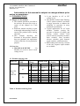
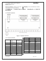
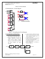
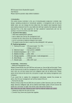
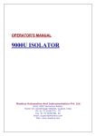
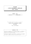
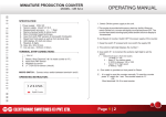
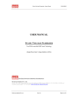
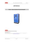
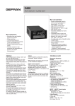
16 CHANNEL DIGITAL INPUT MODULE
Ref No: m11A/om/101
Issue No: 02
masibus
User Manual
16 CHANNEL DIGITAL INPUT MODULE
MASMAS-DIDI-1616-D-
Masibus Automation And Instrumentation Pvt. Ltd.
B/30, GIDC Electronics Estate,
Sector-25, Gandhinagar-382044, Gujarat, India
Phone No : 91 79 23287275 – 79 Fax No : 91 79 23287281, 82
Email : [email protected] Web: www.masibus.com
16 CHANNEL DIGITAL INPUT MODULE
Ref No: m11A/om/101
Issue No: 02
masibus
Contents
1. INTRODUCTION …………………….……………………………...............03
1.1 Purpose of the manual
1.2 Overview
1.3 Product ordering code
2. SPECIFICATIONS…………………….……………………………………..04
2.1 Electrical Specification
2.2 Mechanical Specification
2.3 Environmental condition
3. TERMINAL CONNECTIONS……………………………………………….05
3.1 Connection Details
3.2 Wiring diagram & Circuit Diagram
4. I/O module Operation….……….……………………………………………..06
5. SAFETY AND WARNING PRECAUTIONS…………………….………….07
5.1 Safety Precautions
5.2 Warning Precautions
6. MAINTENANCE………………………………………………………..……07
Figures
Figure 1: On/Off –State Voltage Range ....………………………………………….04
Figure 2: Terminal connection ………………………………………………………05
Figure 3: Wiring Diagram & Circuit Diagram ………………….…………………..06
Figure 4: Block Diagram of I/O Module....…………………………….…………….06
Tables
Table 1: Product ordering code ……….. …………………………………………03
Table 2: Electrical Specification …………………………………………………….04
Table 3: Connection Details ………………………………………………………...05
Table 4: Operation Details …………………………………………………………..06
Note:
masibus
16 CHANNEL DIGITAL INPUT MODULE
Ref No: m11A/om/101
Issue No: 02
Information in this manual is subject to change without prior
notice or permission.
It can interface to AC or DC
1. INTRODUCTION
voltage levels.
The modules feature input filtering,
1.1 Purpose of the manual
5300V optical isolation, and built This manual should be provided to
in surge protection to enhance the
the end user. Keep an extra copy or
reliability of operation in noisy
copies of the manual in a safe
industrial environments.
place.
Typical applications for AC input
Read this manual carefully to gain
modules include sensing the
a thorough understanding of how to
presence or absence of voltage, and
operate this product before starting
sensing contact closure from
operation.
sources such as proximity switches,
This
manual
describes
the
limit switches, float switches,
functions of this product. Masibus
selector switches, push buttons,
does not guarantee the application
toggle switches, and thermostats.
of these functions for any particular
Both sinking and sourcing versions
purpose.
of the fast response input module
are available.
1.2 Overview
MAS-DI-16-D-XXXXX
I/O
Modules are used to detect on/off
voltage levels.
1.3 Product ordering code
INPUT
Input
Model No
TYPE
Voltage
X
X
1
AC
2
MAS-DI16-DXXXXX
DC
1
2
3
4
5
Output
Protection
X
X
NON
230VAC 0 SOURCE 0
FUSE
WITH
110VAC 1 SINK
1
FUSE
220VDC
110VDC
48VDC
24VDC
12VDC
Output Type
Output
Connection
X
0
D-TYPE
1
FRC
Table 1: Product Ordering Code
User Manual
Page 3 of 7
masibus
16 CHANNEL DIGITAL INPUT MODULE
Ref No: m11A/om/101
Issue No: 02
2. SPECIFICATIONS
2.1 ELECTRICAL SPECIFICATION:
2.1.1 INPUT VOLTAGE:
Voltage
Category
Operating
voltage
Number
of input
On state
voltage
(Von)
12V(DC)
7-15V(DC)
16
≥ 7V(DC)
24V(DC)
15-30V(DC)
16
≥ 15V(DC)
48V(DC)
30-55V(DC)
16
≥ 30V(DC)
110V(DC)
70-132V(DC)
16
≥ 70V(DC)
220V(DC)
110-250V(DC)
16
≥ 110V(DC)
110V(AC)
70-132V(AC)
16
≥ 70V(AC)
230V(AC)
110-265V(AC)
16
≥ 110V(AC)
Nominal
Input
Current
8mA at 12
VDC
8mA at 24
VDC
4.2mA at 48
VDC
2mA at
110VDC
2mA at
220VDC
12 mA at
120VAC
12 mA at
230VAC
Off state
voltage
(Voff)
Response
Time
≤ 4V(DC)
≤2mSec
≤ 7V(DC)
≤ 2mSec
≤ 10V(DC)
≤ 2mSec
≤ 30V(DC)
≤ 15mSec
≤ 50V(DC)
≤ 20mSec
≤ 30V(AC)
≤ 10mSec
≤ 50V(AC)
≤ 15mSec
Table2: Electrical Specification
On/Off –State Voltage Range:
Figure 1: On/Off –State Voltage Range
2.1.2 OUTPUT VOLTAGE:
Signal Type: Open Collector
Nominal Voltage: 24VDC
Nominal Current: 5mA
Maximum Voltage: 28VDC
Output ON Status LED: Green
2.1.3 EXTERNAL POWER SUPPLY
: 24V DC
2.2 MECHANICAL SPECIFICATION
Terminals: Phoenix make PCB type
Terminal block can accept up to 2.5 square
mm Wire.
Case: Phoenix make Profile UM-72.
User Manual
Size:200mm (L)X 90mm (W)X 60mm (H)
Mounting: DIN RAIL
Connections: Power, Input & Output as
shown in figure.
Weight: 0.250 Kg.
2.3
ENVIRONMENTAL
SPECIFICATION
Operating temperature: 0°C to55°C
Insulation Resistance: Greater than
200MΩ between all Input channels and
output Channels at 500V DC.
Page 4 of 7
masibus
16 CHANNEL DIGITAL INPUT MODULE
Ref No: m11A/om/101
Issue No: 02
Electrical Isolation: 1500Vac between all
input channels and output Channels.
3. TERMINAL
DIAGRAM
Humidity: 30% to 85% RH non-condense
CONNECTION, WIRING
DIAGRAM & CIRCUIT
3.1 Terminal connection
Figure 2: Terminal connection
3.1.1 Connection Details:
Terminals
1
2
3
4
5
6
7
8
9
10
11
User Manual
25 pin DType
Connector
DI 16
DI 15
DI 14
DI 13
DI 12
DI 11
DI 10
DI 9
DI 8
DI 7
DI 6
20 pin FRC
Connector
DI 16
DI 15
DI 14
DI 13
DI 12
DI 11
DI 10
DI 9
DI 8
DI 7
DI 6
12
13
14
15
16
17
18
19
20
21
22
23
24
25
DI 5
DI 4
DI 3
DI 2
DI 1
NC
NC
NC
NC
NC
NC
NC
+24V
GND
DI 5
DI 4
DI 3
DI 2
DI 1
NC
NC
+24V
GND
Page 5 of 7
masibus
16 CHANNEL DIGITAL INPUT MODULE
Ref No: m11A/om/101
Issue No: 02
Table3: Connection Details
3.2 Wiring Diagram & Circuit Diagram:
Ex+
Ex+
INPUT SIGNAL
X
1
4
2
3
1
4
2
3
ExEx-
+
SW1
DI 1
Ex+
-
X
+
SW2
DI 2
-
Where X = Filtering Circuit (AC Input)
Attenuation circuit (DC Input)
+
SW3
DI 3
-
+
SW4
DI 16
-
Figure.3: Wiring Diagram & Circuit Diagram:
4. I/O MODULE OPERATION:
An input module respond to an
input signal in following manner:
Input filtering limits the effect of
voltage transients caused by
contact bounce and/or electrical
noise. If not filtered, voltage
transients could produce false data.
All input modules use input
filtering.
INPUT
X
OPTICAL
ISOLATION
LOGIC
CIRCUIT
Optical isolation shields back plane
circuits and module logic circuits
from possible damage due to
electrical transients.
Logic circuit processes the signal &
determines the output signal.
An output LED indicates the status
of the output signal.
Block Diagram of I/O Module is
shown in figure 4
OUTPUT
DRIVE
OUTPUT
LED
Where X = Filtering Circuit (AC Input)
User’s Manual
Page 6 of 7
masibus
16 CHANNEL DIGITAL INPUT MODULE
Ref No: m11A/om/101
Issue No: 02
Attenuation circuit (DC Input)
Figure.4: Block Diagram of I/O Module
5. SAFETY AND WARNING
PRECAUTIONS
5.1. Safety Precautions
Dangerous voltages capable of
causing death are sometimes
present in this instrument. Before
installation or beginning of any
troubleshooting procedures the
power to all equipment must be
switched off and isolated. Units
suspected of being faulty must be
disconnected and removed first and
brought to a properly equipped
workshop for testing and repair.
Component replacement and
interval adjustments must be made
by a company person only.
5.2 Warning Precautions
Make all terminations without
applying aux. supply. This
decreases the chances for shock,
fuse blowing / tripping and damage
to unit, because of wrong
connection or loose connections.
All supplies and mainly SMPS
supplies draw huge spike currents
when power is on. If connections
are made while the power is on,
power-on huge currents are applied
more frequently than in normal
case, which may result in damage
to some components.
Hanging wires exert unwanted
pressure on terminations and
should be avoided.
The terminations should be done
using correct type of lugs and
should never be done using
soldered ends or free wires.
Route the wiring through an
approved cable housing to
minimize the risk of accidental
damage.
User’s Manual
NOTE:
UNPACKING: Upon receipt of the
shipment remove the unit form the carton
and inspect the unit for shipping damage.
If any damage due to transit, report and
claim with the carrier. Write down the
model number, serial number, and date
code for future reference, when
communicating with our Customer
Support Division.
6. MAINTANCE
Before installation or beginning of
any troubleshooting procedures the
power to all equipment must be
switched off and isolated. Units
suspected of being faulty must be
disconnected and removed first and
brought to a properly equipped
workshop for testing and repair.
Component replacement and
interval adjustments must be made
by a company person only.
Page 7 of 7