1
USO05354413A
Ulllted States Patent [19]
[11] Patent Number:
Smesny et al.
[45]
[54]
5,132,545
5,225,830
ELECTRODE POSITION CONTROLLER
FOR A SEMICONDUCTOR ETCHING
DEVICE
[75] Inventors: Greg A. Smesny; Roger A. Sikes, both
of Austin; Michael R. Conboy, Buda,
an of Tex‘
.
73
[ ]
A
.
sslgnee
:
.
.
7/1992 Shono et a1. ................... .. 250/4922
7/1993 Andermo et al. ................... .. 341/13
Primary Examiner-Thi Dang
Attorney, Agent, or Firm—Kevin L. Daffer
[57]
ABSTRACT
.
.
.
.
.
vided for use in a semiconductor etching device. The
_ _
electrode position controller, system, and method of use
Sunnyvale, Cahf.
[21] APPL N04 33,025
[22] Filed;
Mar. 18, 1993
[ 2]
Oct. 11, 1994
A high precision electrode position controller is pro
Advanced Mic"? Devices’ Inc ’
5
Illt. Clci ....................... ..
US. . ................................
Date of Patent:
5,354,413
can accurately and repeatedly position a dry etch elec
trode within the etch chamber without having to open
32,
[58] Field Of Search ............. .. 156/626, 627, 643, 345;
the chamber and manually move the electrode. More
Over’ the actual gap between electrodes can be Cali_
bra‘ted each time the etching device is turned on. Fre_
References Cited
qua“ Cahbmno“ °f 59mm electrode P°Sm°“ ensures
the electrodes are positioned parallel to each other and
.
.
. .
at an optimal d1stance therebetween. Accurate position
ing of the electrodes provides a more precise etch rate
us PATENT DOCUMENTS
and a more uniform etch across the wafer surface. By
204/298.03, 298.32; 250/341; 118/712
[56]
3,941,985
3 1976
K
tal. ................. .. 235 151.1
4,114,035
9/1978
Herzog .............. ..
4,724,322
2/1988 Knowles et a1. .................. .. 250/341
4,070,578 1/1978 waxy; a1. ........... .. 25/O/336
repositioning the electrodes and maintaining parallel
‘Sm’ varymg types of matenal can be accurately etched‘
250/211 K
20 Claims, 7 Drawing Sheets
18
20
US. Patent
Oct. 11, 1994
Sheet 1 0f 7
26
1°11
I22
1?- 1,
161-?
; 24
rrrr!
111,111
14/‘
r-l—\
20 J I
FIG. 1
(28
('30
FEW
E2}
4
FIG. 2
5,354,413
US. Patent
Oct. 11, 1994
Sheet 2 of 7
5,354,413
32
i
“1
42
5O
3%4/NKif
48
/,
(~12
US. Patent
Oct. 11, 1994
Sheet 3 of 7
5,354,413
68
COMPUTER U
CONTROLLER
INTERFACE
POWER
SUPPLY
w:
TRANS.
63
FIG. 5
zéwss
A
58
US. Patent
Oct. 11, 1994
Sheet 5 0f 7
5,354,413
REDUCE MOTOR
TORQUES
MOVE ELECTRODE
DOWN SLOWLY
REDUCE MOTOR
TORQUES
NO
DETECTED?
MOVE ELECTRODE
DOWN SLOWLY
UNTIL ALL
MOTORS STALL
STOP MOTORS
MOTORS
ARE
STALLED?
RESTART REMAINING
MOTORS
INCREASE MOTOR
TORQUES
OBTAIN COLD
START Z-PULSE
MOVE ELECTRODE __) AND MIN. POSITIVE
TO UPPER LIMIT
OFFSET AT EACH
LINEAR ENCODER
FIG. 7
ALL
NO
OTORS STALL
AT THE SAME
POSITION?
U.S. Patent
Oct. 11, 1994
Sheet 6 of 7
MOVE ELECTRODE
TO LOWER LIMIT
/
MOVE ELECTRODE
TO UPPER LIMIT
OBTAIN WARM START
Z-PULSE AND MINIMUM
POSITIVE OFFSET AT
EACH LINEAR ENCODER
I
SUBTRACT WARM START
MINIMUM POSITIVE OFFSET
FROM RESPECTIVE COLD
START MINIMUM POSITIVE
OFFSET
I
SOLVE SIMULTANEOUS
EQUATIONS TO OBTAIN
CORRECTION VALUES
I
APPLY CORRECTION
VALUES TO SELECT
MOTOR TORQUES
FIG. 8
5,354,413
US. Patent
0a. 11, 1994
FIG. 9
Sheet 7 0f 7
5,354,413
1
5,354,413
2
respect to the grounded electrode and the gaseous
ELECTRODE POSITION CONTROLLER FOR A
SEMICONDUCTOR ETCHING DEVICE
plasma between the electrodes. Depending upon condi
tions, the voltage differential may be several hundred
volts.
BACKGROUND OF THE INVENTION
5
Dry etching is achieved by placing one or more wa
fers upon the powered electrode. The wafer is thereby
Incorporated herein is a computer program listing
con?gured to receive positive ions directed from the
micro?che appendix of source code used to control and
plasma toward the negatively charged, powered elec
calibrate electrode position within a semiconductor
etching device according to the present invention.
trode. The ions are accelerated substantially perpendic
Copyright, 1993, Advanced Micro Device, Inc. A por
ular to the wafer surface and embed into the surface.
tion of the disclosure to this patent document contains
The ions chemically or mechanically react with the
material which is subject to copyright protection. The
surface, and the reactive material is subsequently evacu
copyright owner has no objection to the facsimile re
ated from the chamber. The amount of reaction is often
production by anyone of the “micro?che appendix”, as
referred to as the etch rate.
it appears in the Patent and Trademark Of?ce ?le or 15
Etch rate can vary depending upon several factors
records, but otherwise reserves all copyright rights
whatsoever.
including: operating pressure within the chamber,
1. Field of the Invention
This invention relates to the manufacture of inte
grated circuits and more particularly to an integrated
ing, inlet gas composition, gas ?ow rate, etc. Etch rate
will therefore increase as the voltage across the elec
trodes or between the powered electrode and plasma
circuit etching apparatus including an improved device,
system and method for calibrating and controlling the
position of electrodes within the etching device.
wafer temperature, electrode voltage, electrode spac
(sheath voltage) increases. Sheath voltage will increase
as the gap between electrodes decreases or if the rf
voltage upon the powered electrode increases.
2. Background of the Relevant Art
Slight changes in the gap or distance between elec
It is well known that during integrated circuit manu 25
trodes
may substantially change the plasma etch rate.
facturing, whole wafers are coated with a layer or lay
Accordingly,
it becomes important to monitor and
ers of various materials such as silicon dioxide, silicon
nitride, or metallization. The unwanted material can be
selectively removed by masked photolithography and
closely control the gap as well as the electrode positions
with respect to one another. It is well known that the
etchants to leave, for example, holes in a thermal oxide 30 electrode material may slightly participate in the etch
reaction and therefore become thinner after a number of
where diffusions are to be made, or long strips of alumi
wafer batches have been processed. After several
num for electrical interconnect between individual cir
batches have been completed, the electrodes must be
cuit elements. Accordingly, fme-line geometries can be
replaced and the new electrodes must be repositioned
produced by removing or etching select regions of
material between the structures.
35 with the chamber. Furthermore, as the electrodes be
come thinner, they often must be repositioned so that
There are several etching techniques commonly used,
the gap between electrodes does not become exceed
including: wet chemical, electrochemical, pure plasma,
ingly large. If the electrodes are not periodically re
reactive ion, ion beam milling, sputtering, and high
placed and the gap re-calibrated, the etch rate may
temperature vapor. Wet etching generally involves
become considerably dissimilar from the target rate.
immersing wafers containing select areas of photoresist
Not only must the gap between electrodes be main
in an aqueous etching solution. Wet etching, while the
tained fairly constant throughout numerous processing
oldest and least expensive technique, is gradually being
replaced by dry etching techniques such as plasma etch
ing and combination plasma/reactive ion etching (RIE).
Plasma and RIE techniques, often called dry etching,
batches, but also the gap must be constant across and
gaseous plasma. Dry etching generally involves fewer
safety hazards and less spent chemical disposal prob
area may be etched dissimilar from a wafer region
between the planar surfaces of the electrodes. If the
45 electrodes are not positioned substantially parallel to
each other, then a wafer region within the larger gap
are relatively new and are performed in low pressure
within the smaller gap area. Maintaining parallelism and
an optimal gap spacing distance is often dif?cult unless
lems, and also produces ?ner line geometric structures.
Dry etching generally requires an etching chamber 50 the operator periodically opens the chamber and per
capable of receiving gaseous etchant. The etchant can
forms calibration measurement on the electrodes. Fre
be pressurized within the chamber and, after etching is
quent opening of the chamber can allow ingress of dust
completed, the gaseous material and volatile by
particles and is also time consuming.
products can be pumped away or evacuated from the
SUMMARY OF THE INVENTION
chamber. Operating pressure depends upon the material 55
being etched, the gas etchant chosen, and may range
The problems outlined above are in large part solved
from a few torr to fractions of a millitorr. The etching
by the electrode position controller of the present in
chamber also includes a pair of electrodes at opposing
vention. That is, the electrode position controller peri
sides or ends of the chamber. One electrode is generally
odically calibrates the position of the electrodes to en
charged by an rf power supply while the other elec 60 sure parallelism throughout processing of numerous
trode is grounded. Typically, the powered electrode is
wafer lots. The calibration routine is performed each
DC isolated from the RF generator by a capacitor in
time the etching device has been modi?ed, reassembled,
order that negative electron charge accumulates upon
or adjusted. Further calibration can take place each
the powered electrode during half the RF cycle while
time the etching device is turned on in order to deter
positive ion charge accumulates during the next half 65 mine actual electrode position for a given set of elec
cycle. Since electrons are more mobile than ions, a
trodes throughout the lifetime of those electrodes. Ac
negative potential will build upon the powered elec
trode in order to charge the electrode negative with
cordingly, periodic calibration allows for the operator
to readjust the electrode position to ensure parallelism
3
5,354,413
and an optimal distance between electrodes without
having to open the etching chamber.
The calibration technique of the present invention is
stored within a programmable computer and, upon
4
having outputs coupled to the motor, are adapted to
produce a drive current of a duration corresponding to
the pulse-width modulated signal.
The present invention still further contemplates a
demand, is sent to the etching device with little or no 5 host computer including a data bus, and means coupled
user interface required. The programmable computer
can also store various gap distances to ensure an optimal
etch rate depending upon chosen processing parame
ters. For example, ultra ?ne-line geometries may re
to the computer for receiving a stream of digital pulses
and also for interpolating each digital pulse. A counter
is coupled to the computer for counting interpolated
pulses, and a register is coupled to the computer for
quire a different gap distance than larger geometries. 10 storing a number of counts associated with the interpo
The optimal gap distances can be stored within the
programmable computer and retrieved with minimum
user interface. Connection between the computer and
the electrode mechanical drive assembly allows the
computer to automatically reset the electrode gap to an
optimal level, and to automatically set electrode paral
lelism. Still further, the user can directly manipulate the
electrode up-down position via a keyboard connected
to the computer. The user can merely enter the desired
positional data into the computer via the keyboard. The
computer then accesses an electrode drive assembly
which then controllably moves the electrode. The user
therefore need not open the chamber to calibrate or
lated digital pulses. The number of counts can be re
trieved and subsequently placed upon the data bus.
The present invention still further contemplates a
method for calibrating the position of an electrode
within a semiconductor etching device. The method
includes the steps of providing four motors having
threaded shafts placed through four corners of a move
able upper electrode and a stationary lower electrode of
the etching device. The upper electrode has a range of
movement between a maximum upper limit and a maxi
mum lower limit. Four linear encoders are also pro
vided, wherein each encoder has a base and an elon
gated body. The base is connected to the lower elec
trode,
and the body extends a spaced distance beyond
etching devices can be attached in serial or parallel 25
the outer edge of the upper electrode. The calibration
fashion to the computer interface to allow positional
technique includes moving the upper electrode toward
control from a remote location.
make small changes to the electrode position. Multiple
Broadly speaking, the present invention contemplates
an electrode position controller for a semiconductor
etching device. The electrode position controller com
prises at least one rotatable shaft having external
threads placeable through an aperture within an elec
trode. Rotation of the shaft causes reciprocating, up
down linear movement of the electrode. A motor is
the maximum lower limit until at least one of the four
motors stalls. Thereafter, it must be determined how
many of the four motors have stalled. The motors
which were late in stalling or did not stall are restarted
and the process is repeated until all four motors stall
simultaneously. Next, the upper electrode is moved to a
maximum upper limit causing each linear encoder to
connected to one end of the shaft to provide the neces 35 produce a z-reference pulse. A stream of pulses are also
produced from each linear encoder representing a dis
sary movement, and at least one linear displacement
tance between the reference point (z-pulse) and the
encoder is coupled near the perimeter of the electrode
to monitor movement of the electrode. The linear en
maximum upper limit. Once the reference point z-pulse
and the stream of motor encoder pulses have been de
corresponding to a location and relative movement of 40 termined, the upper electrode is then moved toward the
maximum lower limit to ensure all four motors stall
the electrode. Drive means is provided for driving the
simultaneously at the same position. Simultaneous stall
motor a controlled distance in response to the location
of the electrode.
of the four motors ensures that all four corners of the
The encoder preferably includes an index grating
upper electrode are equally spaced from the lower elec
placed across one surface of the linear encoder, wherein 45 trode and substantially parallel to the lower electrode.
the index grating is adapted to receive a light source
The calibration method hereof further includes the
directed upon the encoder. The index grating produces
steps of moving the upper electrode to the maximum
a stream of digital pulses during a time in which the
upper limit and thereafter producing a z-reference pulse
light source moves across the index grating. The linear
and a stream of pulses from each of the linear encoders.
encoder also includes a reference grating placed on a 50 The encoder pulses represent a distance between the
select region of one surface of the encoder. The refer
reference point and the maximum upper limit at elec
ence grating is adapted to receive a light source di—
trode regions adjacent each encoder. The relative loca
rected toward the select region upon the encoder. The
tion of each point throughout the upper electrode sur
reference grating produces a z-reference pulse when the
face can be calculated by solving a set of simultaneous
light source strikes the select region.
55 equations. Once the equations are solved, a set of cor
The drive means includes a waveform generator
rected positional values are obtained, whereby the cor
adapted to produce a pulse-width modulated signal, and
rected positional values can be sent to the motors via
coder is capable of generating a stream of digital pulses
a pair of torque ampli?ers having outputs coupled to the
torque ampli?ers in order to realign the upper electrode
motor. Torque ampli?ers are adapted to produce a
substantially parallel to the lower electrode and at a
drive current of a duration corresponding to the pulse 60 known distance from the lower electrode.
width modulated signal.
The position controller of the present invention fur
ther contemplates a host computer having a serial com
munication port, and a control module coupled to the
BRIEF DESCRIPTION OF THE DRAWINGS
Other objects and advantages of the invention will
become apparent upon reading the following detailed
communication port for receiving an instruction signal 65 description and upon reference to the accompanying
from the computer. A waveform generator is adapted
drawings in which:
to receive a pulse-width modulated signal correspond
FIG. 1 is a partial side view of an etching chamber
ing to the instruction signal. A pair of torque ampli?ers,
according to the present invention;
5
5,354,413
FIG. 2 is a partial top plan view of an etching device
according to the present invention;
FIG. 3 is a cross-sectional view along plane 3—-3 of
6
12 relative to lower electrode 14 at a respective corner
of the upper electrode 12. Linear encoders 30 monitor
the relative movement of upper electrode 12 at loca
FIG. 2;
tions between pairs of motors. Four motors M1, M2,
FIG. 4 is a detailed cross-sectional view along region 5 M3 and M4 placed at each corner provide suitable lin
4 of FIG. 3;
ear movement of the upper electrode while capable of
FIG. 5 is a block diagram and associated signal ?ow
maintaining a substantially parallel space or gap be
of an electrode position controller according to the
tween electrode.
present invention;
Referring to FIG. 3, a cross-sectional view along
FIG. 6 is a block diagram of a controller interface
plane 3—3 of FIG. 2 is illustrated. Speci?cally, the
connected with an etching chamber, computer and
mechanism for moving upper electrode 12 and monitor
power transformer according to the present invention;
ing electrode 12 position is shown. Each motor 28 is
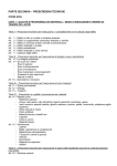
FIG. 7 is flow chart representing cold start electrode
coupled via coupler 32 to one end of a threaded shaft 34.
position calibration according to the present invention;
The threaded shaft, preferably a 2.0 mm pitch precision
FIG. 8 is a ?ow chart representing warm start elec 15 ballscrew, extends through upper apertures 36 placed
trode position calibration according to the present in
vention; and
FIG. 9 is a diagram of an etching device exemplary
electrode orientation and correction values necessary to
?x the position of the electrode and realign the elec
trode.
While the invention is susceptible to various modi?
cations and alternative forms, speci?c embodiments
thereof are shown by way of example in the drawings
through upper electrode 12 and also extends through
lower apertures 38 placed through lower electrode 14.
A suitable ballscrew can be obtained from Nippon
Seiko Corp. of Chicago, 111., part no. Wl20lMA-3PY
C3Z2. A thrust bearing of common design is con?gured
within upper aperture 36 between shaft 34 and upper
electrode 12. A ballnut is con?gured within lower aper
ture 38 between shaft 34 and lower electrode 12. A
suitable ballnut useable with ballscrew 34 can also be
and will herein be described in detail. It should be un 25 obtained from Nippon Seiko Corp. and packaged with
derstood, however, that the drawings and description
part no. Wl20lMA-3PY-C3Z2. The ballnut is thereby
thereto are not intended to limit the invention to the
captured in the drive frame base to allow normal (vac
particular forms disclosed, but on the contrary, the
uum) and reverse (calibration) loads. The thrust bearing
intention is to cover all modi?cations, equivalents and
does not allow lateral movement of upper electrode 12
alternatives falling within the spirit and scope of the 30 relative to shaft 34. Thus, shaft 34, along with upper
present invention as de?ned by the appended claims.
electrode 12 and motor housing 28, move up or down
whenever the motor is actuated and shaft 34 rotates.
DETAILED DESCRIPTION OF THE
Movement occurs by normal camming design at the
INVENTION
ballnut location. Depending upon thread design, clock
Turning now to the drawings, FIG. 1 illustrates a 35 wise rotation of shaft 34 will cause the distal end of shaft
partial side view of an integrated circuit etching cham
34 to extend below the lower surface of lower electrode
ber 10. Chamber 10 preferably includes a moveable
14. Accordingly, upper electrode will move with the
upper electrode 12 and a stationary lower electrode 14.
shaft toward the upper surface of lower electrode 14.
Upper electrode 12 is connected to a power supply,
Conversely, counterclockwise rotation of shaft 34 may
preferably at ground potential 16. Lower electrode is
cause upper electrode 12 to move away from the upper
preferably coupled to an RF supply 18 _via capacitor 20.
surface of lower electrode 14.
Supply 18 can vary in magnitude and period depending
It is important when moving the upper electrode 12
upon the etchant chosen, wafer topography to be
that upper electrode position be closely monitored. A
etched, etch rate, etc. Capacitor 20 is chosen to block
technique for monitoring movement of each motor is
DC voltages upon electrode 14. A reactive gas etchant 45 provided via a motor encoder 40 coupled to the motor
is inserted through port 22 between upper and lower
and shaft 34 for measuring the number of rotations of
electrodes 12 and 14, respectively. A suitable gas etch
shaft 34. Depending upon the number of rotations, the
ant includes a halogen species or various types of Fre
ons” well known in the art. Ions can be formed within
the gas plasma between electrodes, and the ions are
preferably directed in an anisotropic fashion into the
upper surface of wafer 24. The reactant material can
relative movement of upper electrode 12 can be esti
mated therefrom. Unfortunately, movement of shaft 34
does not always correspond with movement of upper
electrode 12. For example, motors 28, which are prefer
ably servo motors, can be back driven out of sync with
then be evacuated from chamber 10 through exhaust
port 26. Wafer 24 thereby receives select etching in
one another, or small back drive motions can occur
whenever power is lost to the motors. Back drive mo
unprotected areas across the upper surface, and the 55 tions can therefore move shaft 34 while not substan
preferred etching technique shown is pure plasma, RIE,
or a combination of pure plasma/RIB.
tially moving electrode 12. In some instances, electrode
12 may become lodged or jammed in position. Such
Referring to FIG. 2, the position and movement of
upper electrode 12 is controlled and monitored in part
would be the case if the electrode gap is substantially
M4, as well as four encoders E1, E2, E3 and E4 are
shown. Each motor can be placed at the corners of
electrode.
In order to monitor the exact and actual position of
upper electrode 12 without having to rely upon inaccu
non-parallel causing lateral pinching movement of the
by one or more motors 28 and linear encoders 30. A 60 shaft against respective apertures 36 and 38 but with
suitable arrangement of four motors M1, M2, M3 and
relatively little linear (up and down) movement of the
upper and lower electrodes 12 and 14, respectively.
Each encoder is attached to lower electrode 14 and 65 rate motor encoders 40, linear encoders 30 are used. A
extends in close spaced arrangement to the outer edge
suitable linear encoder 30 can be obtained from Heiden
or perimeter of upper electrode 12. In the exemplary
arrangement shown, each motor moves upper electrode
hain Corp., Schaumburg, 111., part no. LS2353-2222.
Each linear encoder 30 includes an elongated body 42
7
5,354,413
and base 44. Base 44 is coupled to the stationary lower
electrode 14, and body 42 includes an index grating and
a reference grating placed along one side of the body.
The grating, of common opto-electrical design, is
8
communication path 60 be a conductive cable shielded
from external noise. A suitable cable is a standard class
5 and 7 B8630, VDE0295 which can be obtained from
Parker Hannifm Corp., Rohnert Park, Calif, part no.
adapted to receive a light source attached to a moveable 5 4011.350. Being bi-directional, path 60 allows controller
encoder read head 46. Read head 46 is attached to upper
interface 58 to receive digital pulse stream from motor
electrode 12 and therefore can be moved up or down
encoders 40 and also allows controller interface 58 to
with electrode 12in close proximity to index and refer
send responsive drive current to each motor 28.
ence gratings.
Controller interface 58 can be purchased as a self
Any movement of upper electrode 12 is registered as
an amount of light traversing index gratings placed
upon body 42. In response to light movement across the
gratings, encoder 30 produces a corresponding stream
of digital pulses. Whenever light impinges upon the
reference grating, a z-reference pulse is produced indi
cating a reference position for upper electrode 12.
Pulses within a digital pulse stream are counted when
upper electrode 12 moves past a reference position
contained unit from Parker Hannifm Corp., part no.
88-011270-01 D. Controller interface 58 will be de
scribed in further detail below and will be illustrated in
FIG. 6. Interface 58 contains an RS232 control module
as well as servo drive units capable of generating drive
current sent over path 60 to motors 28. The entire inter
face unit 58 can also be packaged to include four motors
28 and four motor encoders 40. Interface 58 can also be
packaged from Parker Hanni?n Corp. to include an
indicated by an edge-triggered reference pulse. Thus, a
isolating transformer 62. Depending upon interface 58
counter is connected to the output of the pulse stream. 20 load requirements, transformer 62 can be either a single
The counter detects z-reference pulse indicating that
phase or a three-phase transformer. Transformer 62
counting is to begin or that counting is to end.
may have its tappings jumpered for either 120 V single
Upper electrode 12 can move from the reference
phase or 240 V three-phase at the output. A suitable
position to a maximum upper limit or a maximum lower
single-phase transformer can be obtained from Parker
limit. Preferably, reference position is at a midpoint 25 Hannif'm Corp., part nos. T0170 or T0171. Parker Han
between the maximum upper and lower limits. FIG. 4
ni?n Corp. can also provide suitable three-phase trans
illustrates a detailed section view along plane 4 of FIG.
formers, part nos. T0185 and T0186.
3. The detailed view shows a mechanism for measuring
Transformer 62 is typically used to receive an AC
the upper maximum limit. Likewise, a similar mecha
input, either 120 V or 240 V and to convert that output
nism is con?gured near base 44 for measuring the maxi 30 to a level useable by interface 58. Transformer 62 sends
mum lower limit. Maximum limits are obtained when
the output to power supply 64 via path 63, where it is
ever a protrusion or ?ag 48, mounted on upper elec
trode 12, extends a known distance into limit switch 50.
Switch 50 is mounted to the side of body 42 of each
linear encoder 30, and is aligned to receive ?ag 48.
When the distal end of ?ag 48 blocks the light path
between transmit and receive diodes 52, a signal is sent
over wires 54 to motors 28. The signal will indicate that
the motors and attached shaft 34 are to cease rotation. A
suitable transmissive switch 50 can be obtained from 40
Honeywell Corp. of Richardson, Texas, part no.
then converted to a source of varying DC voltages.
Output power supply 64 is coupled to interface 58 as
shown to provide power for interface 58 and associated
brushless servo motors 28 and stepping motor encoders
40. Power supply 64 operates using internal recti?ers
and smoothing capacitors well known in the art. A
suitable power supply can be obtained from Parker
Hannifm Corp., part no. 7705.
Computer 56 includes any standard programmable
device having an XT/AT data bus. A suitable computer
can be obtained from any I.B.M.'-compatible vender
HOA973-T55.
Limit switches 50 placed at maximum upper and
such as, for example, CompuAdd Corp., Austin, Tex.,
lower limits upon encoder 30 signal when electrode 12
model no. 325. Host computer 56 is retro?tted to in
reaches maximum limits. A signal is output from the 45 clude one or more axes interface cards 66 capable of
switches indicating that counting is to begin or to end.
receiving information from indexers 30 over unidirec
The movement of electrode 12 is monitored by starting
tional communication path 68. Interface card 66 can be
the count when the electrode passes the reference point
inserted directly into a full length expansion slot within
or when the electrode starts from a maximum position,
and the count is ended when the electrode stops its
movement. As such, the operator can ascertain the
distance between the current electrode position and
either the reference position or the maximum upper or
maximum lower limit position. Further, the operator
host computer 56. A suitable interface card 66 can be
obtained from Heidenhain Corp., Schaumberg, Ill., part
no. lK-l 10. The operating manual for the Heidenhain
Corp interface card describes the operation of an exem
plary interface card and is herein incorporated by refer
ence.
can obtain the distance between the reference position 55
Encoder 30 provides three channels of information.
and the maximum upper limit or between the reference
The ?rst and second channels each represent a series of
position and the maximum lower limit. Accurate, actual
distances can be obtained at one or all upper electrode
regions adjacent encoders 30.
pulses (one channel of pulses are phase shifted from the
other channel). Depending upon which channel is ad
vanced or retarded from the other, the direction in
Referring now to FIG. 5, a block diagram of an elec 60 which upper electrode 12 is moving can be determined.
trode position controller or position controller system
The third channel is a z-reference pulse which occurs
54 is shown according to the present invention. Elec
trode position controller 54 includes the drive mecha
whenever the light source strikes the reference grating.
Thus, the three channels of information are sent along
nism for an etch chamber 10, a computer 56, and a
path 68 to interface card 66. Interface card 66 includes
controller interface 58. Drive current to each motor 28 65 three inputs to receive each of the channels of informa
and signals from each motor encoder 40 are coupled to
tion. The first and second channels contain streams of
a bi-directional communication path 60 arranged be
pulses which can be interpolated such that several
tween chamber 10 and interface 58. It is preferred that
counts per input signal period can be obtained. For
5,354,413
10
example, up to 200 counts per pulse period can be gen
erated to achieve a higher resolution edge count capa
with brushless servo drive. In this case, they are derived
from encoder 40 and are used for commutation. Enable
bility. Subsequent to interpolation, each interpolated
signal enables and disables motors 28. With a servo
channel is then counted to determine the number of
drive, this signal can disable the motor if a controller
counts prior to the counters being stopped upon receipt 5 fault occurs. It can also reset a fault condition. The fault
of the third channel (or z-reference pulse). The number
of counts can then be sent to registers either within
interface card 66 or to registers within computer 56.
Counted output can be sent directly to the XT/AT bus
in order to allow the user to visually inspect the com
puter monitor screen to obtain the number of counts
corresponding to electrode movement or position.
Computer 56 includes an RS-232C port common with
many standard XT/AT computers. RS-232C is a stan
dard well known in the industry and provides serial
communication between data terminal equipment and
data communication equipment. Interfacing a computer
to a peripheral is one application. A suitable peripheral
is any device which accepts serial communication such
as ASCII format information over a 25-pin RS-232C
connector. A peripheral connected to the RS-232C port
is shown in FIG. 5 as including controller interface 58.
Communication between computer 56 serial port and
controller interface 58 is achieved via bi-directional
communication path 70. Software necessary to present 25
signal derives from the drive to indicate a hardware
power supply or temperature problem within controller
76. PWM torque is the most signi?cant of the seven
signals. PWM (pulse-width modulated) torque signal
consists of pulses at a constant frequency, the width of
the pulses are related to the torque demand of drive
module 78. As the torque demand changes, the mark-to
space ratio will change. A 5% mark-to-space ratio gives
maximum negative torque and a 95% mark-to-space
ratio gives a maximum positive torque. A zero torque is
produced with a 50% mark-to~space ratio. The motor
current, accurately controlled by the PWM signal, is
output by the torque ampli?ers 80 and 82 within drive
module 78. Mode control signal is speci?c to hybrid and
AC brushless servo drive motors using encoder feed
back. It is used in power-up initialization sequences.
Z-channel signal is a signal which monitors the position
of motor shaft 34.
Shaft 34 is monitored by motor encoder 40 housed
within the enclosure at the end of motor 28 (as shown in
communication over path 70 can be obtained from
FIG. 3). Encoder 40 Z-channel signal and index pulse
Parker Hannifm Corp., under the tradename “System
which occurs once per shaft revolution, is processed in
control module 76 to track rotational position of shaft
34. The seven signal link from control module 76 is
connected to drive module 78 and more speci?cally to
waveform generator 84. Drive module 78 comprises a
Seven X-series Commands”. A summary listing of ex
emplary X-series software commands is available from
Parker Hanni?n Corp. and is herein incorporated by
reference. The System Seven user manual for controller
interface 58 part no. 88-011270-01 D, including a de
dual torque ampli?er 80 and 82 to supply controlled
tailed listing of each X-series command, is available in
its entirety from Parker Hanni?n Corp.
current to each motor 28. Input to waveform generator
84 is from control card 76 via opto-isolators common in
Referring now to FIG. 6, a block diagram of control 35 the art. These input signals are used within waveform
ler interface 58 is shown along with connections to
generators 78 to generate the torque demand signals and
motor 28, motor encoder 40, transformer 62 and com
send those signals to torque ampli?ers 80 and 82 as
puter 56. X-series commands are sent between com
shown. Torque ampli?ers 80 and 82 supply current with
puter 56 and controller interface over path 70. Path 60
the appropriate pro?le and phase to motor windings
(shown in FIG. 5) includes conductors 72 which re 40 within each motor 28 under the control of the wave
ceive signals from encoder 40 to control module 76, and
form generator 84. A switched mode power supply 86
further includes conductors 74 which receive signals
operates at a frequency of approximately 80 KHz and
from torque ampli?ers 80, 82 to motor 28. Control mod
uses output from transformer 62 to generate the internal
ule 76, which is part of interface 56, receives signals
supplies needed by drive module 78. In addition to
from motor encoder 40 as well as X-series commands 45 these, two isolated supplies are generated. Five volt
from computer 56 via path 70. Output from control
power supplies are available to power the control mod
module 76 includes a standard seven-signal link neces
ule logic and the motor encoder. Twelve volt power
sary to control any type of servo motor. Thus, control
module 76 functions with any type of servo motor such
as a hybrid, AC brushless system, open loop stepper,
and a brush DC servo. The seven signals link control
module 76 to drive module 78, and provide all neces
sary information to activate and deactivate drive mod
ule 78 and connected motors 28. FIG. 6 illustrates, for
simplicity purposes, connection to only a single motor.
supplies are available for external machine control such
as limit switches (i.e., limit switches 50 shown in FIG.
4).
Waveform generator 84 is part of controller interface
58 and therefore available from Parker Hannifan Corp.
under self-contained package, part no. 88-011270-01 D.
However, individual waveform generators can also be
obtained from Parker Hannifan Corp., part no. 7252.
However, it is understood that multiple control mod
Waveform generator 84 includes an EPROM which
ules and drive modules can be used and placed within
characterizes the drive (hybrid brushless) and contains
controller interface 58 to drive multiple motors 28 and
the instructions necessary for an internal gate array to
receive information from multiple motor encoders 40.
generate the appropriate current pro?les. To generate
Communication path 70 can also be daisy chained to 60 the drive currents, an electrical position latch (EPL)
several control modules and drive modules contained
monitors the position of the rotor using information
within one or more controller interface units 58.
input from the encoder 40 and uses this to generate the
The seven signals sent from control module 76 to
required current pro?le. PWM torque signal determines
drive module 78 are standard signals sent between a
the level of current required by motor 28 to follow the
controller and a servo motor drive. The seven signals 65 input motion pro?le sent from encoder 40 or computer
are fully opto-isolated at the drive end to eliminate the
56. These two sets of data are fed into two digital-to
problems arising from electrical noise. Step and direc
analog (DAC) converters which provide the analog
tions signals, the usual inputs to a stepper drive, are used
torque demand signals for the two torque ampli?ers 80
11
5,354,413
and 82. The output current from ampli?ers 80 and 82
may be limited to a maximum level by the setting of the
current limit switches (see FIG. 4) mounted at the maxi
12
(9) Quit.
To form an operation, the user need simply to type
the number associated with that. operation and hit the
return or enter key. Instructions are provided by each
screen throughout the system program. All the individ
ual operations are described in detail below:
(1) “Use cursor keys to move drive plate with coarse
positioning” allows the operator to coarsely move the
drive plate or upper electrode 12 using the up and down
mum upper and maximum lower limit of electrode
movement range.
When controller interface 58 is switched on, motor 28
is powered up as an open loop stepping motor and the
rotor will rotate to locate its nearest step. This allows
drive encoder 40 to de?ne a known electrical position.
A mode input is then used to apply the necessary 90°
torque angle and current is adjusted to maintain motor
rotor position. If there is signi?cant friction load on the
motor, this procedure may result in operation at a non
optimal torque angle for up to one revolution of the
motor shaft. The electrical position signal will then be
keyboard cursor control arrows. The actual distance
moved by each coarse cursor entry is by default 1.0 mm.
(2) “Use cursor keys to move drive plate with ?ne
positioning” allows the operator to move the drive plate
or upper electrode 12 in ?ner steps. The actual distance
moved by each ?ne cursor entry is by default 0.1 mm.
reset by encoder pulses sent across conductors 72, and
any error in torque angle will be corrected.
lows the operator to move the drive plate or upper
It is appreciated from the block diagram of FIG. 6
electrode 12 a speci?ed distance de?ned by the user.
(3) “Move drive plate some speci?ed distance” al
that control module 76 is used to control the drive nec
When prompted, the user de?nes a distance in which
essary to controllably activate motor 28. Control mod 20 the electrode shall be moved in either a positive “up”
ule 78 receives its stimulus from one of two sources.
position or a negative “down” position. A negative
Module 76 can receive input from motor encoders 40
distance will therefore decrease the gap distance be
which constantly monitor shaft 34 position. Otherwise,
tween electrodes.
control module 76 can receive input from computer 56.
(4) “Change movement parameters” allows the user
Computer 56 includes an interface card which receives 25 to change the distance moved for both course and ?ne
input from linear encoders 30 to constantly monitor the
positioning from the default amounts described above in
position of upper electrode 12. As such, control module
can send varying torque levels at varying durations to
(l) and (2) above.
one or more motors 28 depending upon the number of
to view the current values of encoders 30. This allows
(5) “Show position of linear encoder” allows the user
pulses sent from motor encoder 40 or index encoder 30.
Each motor can be controlled transparent to the user
via encoder 40 and control module 78. It is not neces
sary that the user always interface with controller inter
the user to quickly display the actual position of elec
trode 12 with respect to electrode 14.
(6) “Show motor status” allows the user to view the
current values of the drive motors 28 and encoders 40.
This will help the user to monitor the motors for proper
operation as well as shaft 34 position. The motor en
coder values do not override the linear encoder values
which are purposefully dissimilar from each other.
face 58 unless the user desires a more accurate control
methodology. If the user wishes to directly interface
with one or more motors 28, then he or she may do so
by entering commands into computer 56 via an associ
ated keyboard. Included herein is a “micro?che appen
(7) “Perform COLD START calibration” allows the
dix” containing a source code listing of various com
user to bring the drive plates or electrodes 12 and 14 in
mands, calibration and ?ow operations necessary to
allow a user to directly interface with control module
parallel position. Cold start must be performed anytime
the etch device is disassembled, physically readjusted,
78 via X-series commands described above.
Loading the necessary source code into computer 56
memory allows the user to access the software directly
or after any other operation which would invalidate the
last cold start calibration data. It may also be prudent or
necessary to perform this operation periodically to en
by starting the program through a command RUN 45 sure that the system meets all tolerances and speci?ca
LAM when the DOS prompt appears on the screen.
trons.
Execution of RUNLAM program clears the screen and
(8) “Perform WARM START calibration” allows
informs the user that the control system 54 is about to
the user to bring the drive plates or electrodes 12 and 14
perform a warm start calibration routine described
in parallel position. It is recommended that warm start
below (see FIG. 8). It also states that the user can press 50 be performed each time the motors are enabled, or a
certain keys to cancel the warm start calibration pro
nonparallel error may accumulate. Warm start calibra
gram. If cancellation does not occur, warm start cali
tion relies on previous cold start calibration to ensure
bration will automatically begin.
proper electrode calibration. Warm start calibrates the
Once warm start calibration has completed, upper
electrodes at actual position for a ?ne-tune calibration
electrode 12 will move to maximum lower limit and 55 operation beyond merely estimated cold start electrode
then to a maximum upper limit. The screen will clear,
calibration.
and an exemplary main menu will appear having the
(9) “Quit” allows the user to stop etching operation
following options displayed:
and returns the user to the DOS prompt. It is important
(1) Use cursor keys to move drive plate with coarse
that the etching chamber not be evacuated when the
positioning.
user selects this operation.
(2) Use cursor keys to move drive plate with ?ne
FIG. 7 illustrates a ?ow'diagram of the cold start
positioning.
calibration process. When the cold start calibration
(3) Move drive plate some speci?ed distance.
(4) Change movement parameters.
(5) Show position of linear encoders.
(6) Show motor status.
(7) Perform COLD START calibration.
(8) Perform WARM START calibration.
option is selected from the main menu, the operating
system asks the user to con?rm that he or she wants to
65
perform cold start calibration. Upon con?rmation, cali
bration begins as shown in FIG. 7. The calibration pro
cess can be interrupted at any time by using the ESC
key upon computer 56 keyboard. System software be
13
5,354,413
gins by reducing output from torque ampli?ers 80 and
14
electrode 12 and the other edge of electrode 12. One
edge cannot be more than 0.0001 inches below the other
edge. This value of 0.001 inches is programmed as a
82 thereby allowing electrode 12 to move down slowly
toward stationary electrode 14. Eventually, at least one
motor placed at one of the corners of the upper elec
system constant and can be modi?ed. It does not repre
trode will stall. The motor which stalls is thereby asso~ 5 sent a physical limitation.
ciated with the electrode 12 corner which initially
Referring now to FIG. 8, a warm start calibration
contacts lower electrode 14. At this point, the stalled
program is illustrated. As described above, each time
motor corresponds with the lowest point on the upper
the position controller system 54 is restarted, warm start
electrode carriage. The remaining motors are then
calibration is performed. Warm start calibration ensures
stopped and a determination is made as to whether or
that the electrode plates are substantially parallel to
not all motors are stalled. If all the motors are not
each other, and restored to the parallel condition devel
stalled, then the remaining motors are then restatted and
oped during the cold start routine. Furthermore, warm
driven down until another motor then stalls. The pro
start calibration uses previous cold start calibration
cess is repeated for all the remaining motors until all
offsets and z-reference pulse signals at the linear encod
motors are stalled (i.e., until the last singly driven motor 15 ers. As mentioned above, cold start calibration is only
is driven to a stall). At that time, all four motors are
done in certain instances, as it develops wear and tear
restarted under full torque, raised, reduced in maximum
upon the motors and linear encoders, and is usually
torque and eventually lowered with the vacuum load of
done only when the system is mechanically disassem
etch chamber 10 to verify that all four motors stall
bled or modi?ed. Otherwise, warm start is suf?cient to
effectively simultaneously within a tolerance band spec
restore the parallel state developed by the cold start
i?ed as a system constant. As noted above, subsequent
routine, and may also be used, when modi?ed mathe
stalls cause back drive in previous stalled motors
matically, to update a parallel condition as adjusted for
thereby allowing shaft positions to realign with one
electrode wear.
another.
Warm start begins by driving electrode 12 until a
During the time in which electrode 12 is moved 25 signal is received from switch 50 indicating the maxi
toward an upper maximum limit, a z-reference pulse is
mum upper position has been reached. Then, electrode
obtained as well as a number of pulses representing a
12 is driven to the minimum position signalled by the
minimum positive offset from each linear encoder 30.
switch assembly 50 indicating that the electrode has
The z-reference pulse is one pulse sent by each linear
reached the lowest possible point. Electrode 12 then
encoder 30 representing approximately the midpoint
travels upwards, during which time the system control
between maximum upper limit and minimum lower
ler 56 monitors linear encoders 30 until z-pulses are
limit. The minimum positive offset is obtained at each
returned from each linear encoder. As each z-pulse
linear encoder representing the distance between the
occurs, a count is begun. When the electrode 12 reaches
midpoint (or reference point) on which z-reference
the uppermost position again, a set of four counts R1,
pulse is obtained and a maximum upper limit (obtained 35 R2, R3 and R4 corresponding to each linear encoder 30
by a signal sent from switch 50). The minimum positive
(E1 through E4, respectively) offset values from each
offset value representing a count number of pulses can
z-pulse to the uppermost reachable position. The small
be stored for subsequent use (e. g., for subsequent use in
est of these four values is then subtracted from the four,
the warm calibration routine described below and
yielding a set of four minimum positive values, one of
shown in FIG. 8). The z-reference pulse is thereby a 40 which must be zero.
single reference point along the path of travel of the
The minimum positive offsets (R1 through R4) at each
linear encoder. By approaching this point from a known
linear encoder 30 obtained during warm start can then
direction and monitoring for a pulse signal transition
be subtracted from the minimum positive offset (P1
“edge” a single reference point can be precisely known.
through P4) at each linear encoder 30 obtained during
Offsets from this point can be noted for additional refer 45 cold start to obtain a set of simultaneous equations nec
ence locations. Speci?cally, offsets between maximum
essary to obtain positional values across electrode 12
upper limit and z-reference pulse described above are
surface in relation to electrode 14 surface. An exem
designated as minimum positive offsets for each linear
encoder 30 and denoted herein as P1, P2, P3, and P4. P1,
plary set of simultaneous equations and the calibration
methodology used to obtain those equations are de
P2, P3, and P4 correspond with linear encoders E1, E2, 50 scribed below.
E3 and E4, respectively, as shown in FIG. 2. Differ
Warm start calibration is generally necessary when
ences between each motor encoder offset are common
ever system 54 looses motor power while chamber 10 is
due to differences in manufacturing tolerances and
under vacuum load. Warm start is also necessary if
mounting locations between each linear encoder and
system 54 has been restarted and brought under vacuum
electrodes 12 and 14.
55 load subsequent to a normal restart, or when any other
Once the z-reference pulse and minimum positive
condition exists where calibration data is valid but cur
offsets of each encoder 40 are determined during cold
start calibration, motor torques are reduced as indicated
rent electrode position is not valid. The failure to con
duct warm starts when necessary may result in a build
up of error which may cause a drive fault. This may
in FIG. 7, and then electrode 12 is moved slowly down
until all motors stall simultaneously. If all motors stall at 60 happen whenever the drive motors are completely inde
the same position (within a tolerance range), then cold
pendent and may be back driven out of sync with one
start calibration is completed. If the motors stall dis
another. If the operator, for example, cuts motor power
tinctly from each other (outside a tolerance range), then
by exiting program software while the vacuum cham
cold start calibration is rerun until the system program
ber is evacuated, small back drive motions may cause a
achieves the tolerance stall condition. Preferably toler 65 loss of parallelism. Should the operator then restart the
ance stall range is less than approximately 0.0001 inches.
program software and immediately abort auto warm
Tolerance stall condition of 0.0001 inches represents the
start calibration, the fault will not be corrected and the
maximum positional difference between one edge of
motors will still run. Should this series of events be
15
5,354,413
repeated, the non-parallelism may grow so large that
motors 28 and shafts 34 will bind during their motion.
This situation is to be avoided since signi?cant misalign
ment may damage shafts 34 and linear encoders 30.
16
Scaling factor “s” is the marginal difference between
linear encoder 30 readings and motor encoder 40 read
ings. Thus, dE=s*dM. Factor s depends upon the reso
lution selected from the interface card 66 placed within
computer 56, and is also dependent upon the resolution
demanded by motor encoders 40 since both sets of sys
tems (encoder 30 and encoder 40) are recon?gurable).
The sequential positional values X, Z and C can be
found by solving for each of these values in a set of
Combined cold and warm start calibration necessary
to obtain simultaneous equations and correction values
are best described using a square electrode example.
Shown in FIG. 9 is a diagram of electrode 12 exemplary
orientation and positional values X, Z and C obtained
from an exemplary four cornered electrode 12. The
positional values can be used to correct any misalign
ment associated with electrode position and, once ob
simultaneous equations obtained from the difference
between encoder offsets (i.e., solving for differences
between P1 through P4 and R1 through R4) as described
tained, negative amounts applied to each positional
below:
value represent correction values necessary to realign
electrode 12 parallel with electrode 14 and at a known
distance from electrode 14. Motors M1 through M4 are
suitably placed at each corner of the square electrode,
and encoders E1 through E4 are placed at the outer
edge of the electrode between adjacent corners.
Using the exemplary electrode shown in FIG. 9, M1
20
and M2 can be moved such that electrode 12 position at
M1 and M2 is a positive X distance above the motor
Note that the determination of positional values and
therefore the determination of correction values in
position at M3 and M4, the result of this motion will be
to tilt the upper electrode about an axis through linear
encoders E2 and E4. Another set of motor moves can 25
volves solving four equations with three variables. One
apply to motors M2 and M3. Motors M2 and M3 can
move in a positive Z direction extending above motor
locations M1 and M4 to cause electrode 12 to tilt about
an axis through linear encoders E1 and E3. Movement
in a Z direction of M2 and M3 is about an axis which is
can solve for any three equations and be assured the
fourth should be satis?ed automatically as long as the
approximations of the calibration program are correct.
thereby orthogonal to the axis of the ?rst tilt provided
by motion X.
It is well known in geometric application that the
position of a substantially planar member, such as elec
Once X, Z and C are obtained, given a speci?c scaling’
factor S, it is a fairly simple procedure to enter those
positional values via computer 56 into the main display
menu. Variousv techniques can be used to move elec
trode 12 to a corrected or calibrated position given the
positional values. Electrode 12 can be moved by enter
trode 12, can be determined or ?xed in two rotations 35 ing the correction values into computer 56 via keyboard
and along one linear direction when one other rotation
cursor described above, causing controller interface 58
is speci?ed. Furthermore, since electrode 14 is station
and motors 28 to reciprocate. The correction values can
ary at a known position, gap separation along the entire
therefore be applied to select motor torques necessary
gap area between electrodes 12 and 14 can be easily
to move one or more shafts 34 a controlled distance in
determined once the two rotations and one linear direc 40 order to achieve accurate and parallel position of elec
tion are ascertained. The linear direction or movement
trode 12. Electrode 12 can be positioned and reposi
of electrode 12 is designated as motion C. Motion C
tioned via computer input in response to X, Z and C
represents a certain movement of each and every point
indicia without opening chamber 12. Furthermore, re
of electrode 12 either positively away from electrode 14
positioning can be performed easily and quickly from a
or negatively toward electrode 14.
45
remote computer location to several possible chambers
As an approximation, it is proper to assume motors
10 connected in parallel.
M1 through M4 are near or adjacent the corners of the
It will be appreciated to those skilled in the art having
exemplary square electrode shown in FIGS. 2 and 9,
the bene?t of this disclosure that this invention is be
and that the linear encoders 30 are at the midpoints of
lieved to be capable of applications with numerous
each side exactly between pairs of adjacent motors. The
types of semiconductor etching devices using a dry etch
motion at encoders 30 due to the motion X described
procedure. An exemplary etching device can be ob
above will be as follows:
E1: sx
E2: 0.5 SX
E3: 0
tained from LA34 Research Corp. of Fremont Calif.,
model no. 490/590. It is to be understood that the form
55 of the invention shown and described is taken as a preset
preferred, exemplary embodiment. Various modi?ca
The motion at linear encoders 30 due to motion Z de
scribed above will be as follows?
tions and changes may be made without departing from
the spirit and scope of the invention as set forth in the
B1: 0.5 sz
claims. An exemplary modi?cation might be one which
B3: 0.5 52
uses a dissimilar arrangement of motors and encoders
placed upon either a moveable upper electrode or a
E4: 0
The motion at linear encoders 30 due to motion C de
scribed above will be as follows:
E1:
E2:
E3:
B4:
sc
sc
sc
SC
moveable lower electrode. It is intended that the fol
lowing claims be interpreted to embrace all such modi?
cations and changes.
What is claimed is:
65
1. A method for calibrating the position of an elec
trode within a semiconductor etching device, compris
ing the steps of:
17
5,354,413
18
providing four motors having threaded shafts placed
means connected on said upper electrode and said
through four corners of a moveable upper elec
trode and a stationary lower electrode of a semi
lower electrode between said shaft and said upper
aperture and between said shaft and said lower
conductor etching device;
aperture, respectively, for moving said upper elec
trode and shaft relative to said lower electrode;
providing a maximum upper limit and a maximum
lower limit range of movement for said upper elec
at least one encoder attached to the lower electrode
providing four linear encoders, each linear encoder
having a base and an elongated body, wherein said
and having an index grating and a reference grating
placed along one side of said encoder, said index
grating is adapted to produce a stream of digital
base is connected to said lower electrode and said
body extends a spaced distance beyond an outside
pulses corresponding to a distance in which said a
light source attached to the moveable said upper
trode;
edge of said upper electrode;
moving said upper electrode toward said maximum
lower limit until at least one of said four motors
stalls;
15
determining how many of the four motors have
stalled;
restarting the motors which have not stalled and
repeating the immediately preceding two steps
until all four motors have stalled;
moving said upper electrode to said maximum upper
limit;
producing a cold start z-reference pulse from each
said linear encoder and a cold start stream of pulses
from each said linear encoder, wherein said cold 25
start stream of pulses represents a distance between
a point in which said cold start z-reference pulse is
produced and said maximum upper limit; and
moving said upper electrode toward said maximum
electrode extends along said index grating, said
reference grating is adapted to produce a Z-refer
ence pulse when said light source strikes said refer
ence grating;
a host computer coupled to receive and count said
stream of digital pulses prior to and after receiving
said Z-reference pulse;
a torque ampli?er adapted to deliver activation cur
rent to said motor, whereby rotation of said motor
causes said upper electrode to move in relation to
said lower electrode; and
means activated by said host computer for transmit
ting a pulse-width modulated signal to said torque
ampli?er, said signal is modulated according to the
distance in which said light source extends across
said index grating prior to said light source striking
said reference grating.
4. The etching device as recited in claim 3, wherein
said etching chamber is adapted to receive an etchant
lower limit to ensure all four motors stall simulta
gas.
neously at the same position and said four corners
5. The etching device as recited in claim 3, wherein
of said upper electrode are equally spaced from
said upper and lower electrodes are adapted to receive
said lower electrode and substantially parallel to
a voltage differential therebetween.
said lower electrode.
35
6. The etching device as recited in claim 3, wherein
2. The method as recited in claim 1, further compris
said moving means comprises a camming ballnut con
ing the steps of:
?gured between said lower aperture and said shaft.
moving said upper electrode to said maximum upper
7. The etching device as recited in claim 3, wherein
limit;
said moving means comprises a thrust bearing con?g
producing a warm start z-reference pulse from each
ured between said upper aperture and said shaft.
said linear encoder and a warm start stream of
8. The etching device as recited in claim 3, wherein
pulses from each linear encoder, wherein said
said motor comprises a motor encoder adapted to pro
warm start stream of pulses represents a distance
duce a stream of digital pulses corresponding to a num
between a point in which said warm start z-refer
ber of rotations of said motor.
ence pulse is produced and said maximum upper 45
9. The etching device as recited in claim 8, wherein
limit;
said transmitting means comprises a control module
counting said warm start stream of pulses and count
coupled to receive said stream of digital pulses from
ing said cold start stream of pulses at each said
said host computer and said stream of digital pulses
linear encoder;
from said motor encoder.
subtracting the counted number of warm start stream 50
10. The etching device as recited in claim 9, further
of pulses from the counted number of cold start
comprising means for driving said motor a controlled
stream of pulses;
distance in response to the number of pulses within said
solving simultaneous equations to obtain a set of cor
stream of digital pulses.
rected positional values of said upper electrode;
11. The etching device as recited in claim 3, further
and
55 comprising:
applying said corrected positional values to select
four threaded shafts placed through four threaded
said motors to realign said upper electrode substan
upper apertures and four threaded lower apertures,
tially parallel to said lower electrode and at a con
said upper and lower apertures are arranged near
trolled distance from said lower electrode.
the four corners of a substantially square said upper
3. A semiconductor etching device comprising: an
and lower electrodes;
etching chamber surrounded by an inner sidewall of a
four motors, each motor is connected at one end of
stationary housing and inner surfaces of an upper elec
each threaded shaft; and
trode and a lower electrode;
four encoders, each encoder having a base and a
at least one threaded shaft placed through a threaded
vertically extending body, wherein said base is
upper aperture extending through said upper elec 65
connected to said lower electrode inside the outer
trode and through a threaded lower aperture ex
perimeter of said lower electrode and between a
tending through said lower electrode;
pair of lower apertures, and said body extends
a motor connected to one end of said shaft;
substantially perpendicular from said lower elec
19
5,354,413
trode and a spaced distance beyond the outside
edge of the outer perimeter of said upper electrode.
12. An electrode position controller for a semicon
ductor etching device comprising:
20
at least one torque ampli?er having outputs coupled
to said motor and adapted to produce a drive cur
rent of a time duration corresponding to said pulse
width modulated signal.
at least one rotatable shaft having external threads 5
placeable through an aperture con?gured within an
18. The position controller as recited in claim 1,
wherein said position controller further comprising:
electrode, wherein rotation of said shaft causes
a host computer including a serial communication
port;
reciprocating movement of said electrode;
a control module coupled to said communication port
to receive an instruction signal from said computer;
a waveform generator adapted to receive a pulse
a motor connected to one end of said shaft;
at least one encoder coupled near said electrode for
generating a stream of digital pulses corresponding
to a location of said electrode; and
means for driving said motor a controlled distance in
response to the location of said electrode.
13. The position controller as recited in claim 1, 15
wherein said encoder comprises an index grating placed
width modulated signal from said control module '
corresponding to said instruction signal; and
a pair of torque ampli?ers having outputs coupled to
said motor and adapted to produce a drive current
to said motor of a duration corresponding to said
pulse-width modulated signal.
across one surface of said encoder, said index grating is
19. The position controller as recited in claim 1,
adapted to receive a light source directed toward said
wherein said position controller further comprising:
encoder.
14. The position controller as recited in claim 13, 20 a host computer including a data bus;
means coupled to said computer for receiving said
wherein said index grating produces said stream of
digital pulses as said light source moves across said
stream of digital pulses and for interpolating each
said digital pulse;
index grating.
15. The position controller as recited in claim 1, 25
wherein said encoder comprises a reference grating
placed across a select region of one surface of said en
a counter coupled to said computer for counting
interpolated said digital pulses;
a register coupled to said computer for storing a num
ber of counts associated with interpolated said
coder, said reference grating is adapted to receive a
digital pulses; and
light source directed toward said select region.
addressing means coupled to said registers for retriev
16. The position controller as recited in claim 15, 30
ing said number of counts and for placing said
wherein said reference grating produces a Z-reference
number of counts upon said data bus.
pulse when said light source strikes said select region.
20. The position controller as recited in claim 19,
17. The position controller as recited in claim 1,
wherein said data bus is connected to a peripheral de
wherein said driving means comprises:
vice, wherein said peripheral device comprises a key
a waveform generator adapted to receive a pulse 35 board and a monitor.
width modulated signal; and
*
45
55
65
*
*
*
*
UNITED STATES PATENT AND TRADEMARK OFFICE
CERTIFICATE OF CORRECTION
PATENT NO. 1
5,354,413
DATED
3
|NVENTOR(S) 1
October 11, 1994
Smesny et al
It is certified that error appears in the above-indenti?ed patent and that said Letters Patent is hereby
corrected as shown below:
Claim 13, col. 19, line 15, please delete ."claim' 1" and substitute
therefor —— claim l2--.
Claim 15, col. 19, line 25, please delete "claim 1" and substitute
therefore --cl'aim l2--.
Claim 1?, col. 19, line 33, please delete "claim 1'' and substitute
therefor “claim l2—-.
Claim 18, col. 20, line 5, please delete "claim 1" and substitute
therefor --claim l2--.
Claim 19, col. 20, line 18, please delete "claim 1'' and substitute
therefor -—claim 12——.
Signed and Sealed this
Seventeenth Day of January, 1995
BRUCE LEHMAN
Arresting Officer
Commissioner of Parents and Trademarks