1
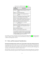
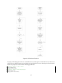
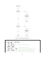
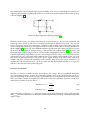
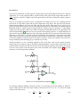
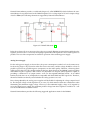
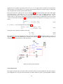
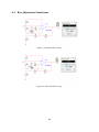
Figure 6.18: LM2941 Schematic [52]
According to the datasheet, the output voltage can be calculated using the following equation:
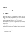
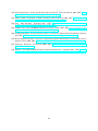
R1 + R2
VOU T = VREF
R1
(6.9)
With a desired output voltage of 5V, VREF = 1.275V per the datasheet, and a chosen value of R1 = 8.2kΩ,
R2 would equal 23.957kΩ. The closest common value is 24kΩ, which would yield an output voltage of:
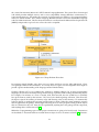
8.2kΩ + 24kΩ
= 5.007V
(6.10)
VOU T = 1.275
8.2kΩ
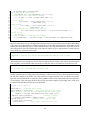
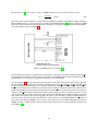
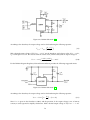
For the LM2991 Negative Regulator, National Semiconductor provides the following suggested circuit:
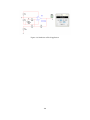
Figure 6.19: LM2991 Schematic [53]
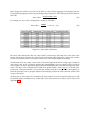
According to the datasheet, the output voltage can be calculated using the following equation:
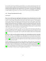
R2
VOU T = VREF 1 +
− (IADJ R2 )
R1
(6.11)
Since IADJ is given in the datasheet as 60nA, and the precision of the output voltage is not of utmost
concern, it can be ignored to simplify calculations. With a desired output voltage of -5V, VREF = −1.21V
73