1
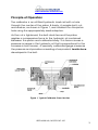
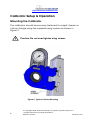
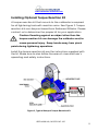
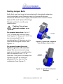
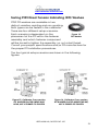
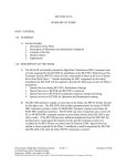
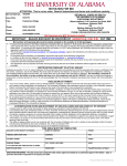
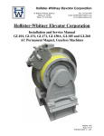
USER MANUAL MODEL MZ-100 BOLT TENSION CALIBRATOR 442 SOUTH GREEN ROAD SOUTH EUCLID, OHIO 44121 USA VOICE: 216-481-4774 FAX: 216-481-2427 www.skidmore-wilhelm.com TABLE OF CONTENTS Introduction .................................................................................... 2 Typical Testing Applications ...................................................... 2 Safety ........................................................................................ 2 Principle of Operation ................................................................ 3 Calibrator Setup & Operation......................................................... 4 Mounting the Calibrator ............................................................. 4 Installing Optional Torque Reaction Kit ..................................... 5 Installing Adaptors ..................................................................... 6 Installing the Fastener Assembly to be Tested ......................... 7 How to Read the Gage .............................................................. 8 Testing Procedures ................................................................... 9 Special Testing Applications ........................................................ 10 Testing Short Bolts .................................................................. 10 Testing Longer Bolts ............................................................... 11 Testing Tension Control (TC), “Twist-Off” Bolts ...................... 12 Testing F959 Direct Tension Indicating (DTI) Washers .......... 13 Rotational Capacity (ROCAP) Testing ........................................ 15 Calibration .................................................................................... 16 Maintenance ................................................................................ 16 Product Specifications ................................................................. 17 Reference Information ................................................................. 18 www.skidmore-wilhelm.com Introduction Thank you for purchasing the Skidmore-Wilhelm MZ-100 Bolt Tension Calibrator. Our improved lightweight design builds on over 50 years of industry leading experience in bolt tension measurement and calibration while maintaining the accuracy, reliability, ease of use and technical support that you have come to expect from Skidmore-Wilhelm. Typical Testing Applications The calibrator can be used to measure fastener tension in a wide variety of applications including but not limited to: Calibration of tightening tools, pre-installation verification, rotational capacity tests and other fastener tests. The calibrator is compatible with all tightening tools including: manual and impact wrenches, pneumatic/hydraulic/electric wrenches and hydraulic tensioners, etc. Fastener elements that can be tested include: hex bolts, threaded studs, tension control (TC) bolts, Direct Tension Indicating (DTI) washers, anchor bolts, lock nuts, etc. Safety Safety First. Read all instructions, warnings and cautions carefully. Follow all safety precautions to avoid personal injury or property damage during use. Skidmore-Wilhelm cannot be responsible for damage or injury resulting from unsafe product use, lack of maintenance or incorrect product and/or system operation. Contact Skidmore-Wilhelm when in doubt as to the proper safety precautions and operations. Failure to follow the proper safety procedures can cause equipment damage and/or personal injury. 2 © Copyright 2009 Skidmore-Wilhelm, Tungsten Capital Partners LLC All rights reserved including illustrations. Revision: 2/2010 Printed in USA www.skidmore-wilhelm.com Principle of Operation The calibrator is an oil filled hydraulic load cell with a hole through the center of the piston & body. A sample bolt, nut, and washer, as shown in Figure 1, are installed thru the piston hole using the appropriately sized adaptors. As the nut is tightened, the bolt stretches and the piston applies a compressive force to the hydraulic oil contained between the piston and calibrator body. This force causes a pressure increase in the hydraulic oil that is proportional to the increase in bolt tension. A specially calibrated gage measures the pressure and provides a reading of equivalent tensile force developed in the bolt. Figure 1, Typical Calibrator Cross-Section USER MANUAL, MODEL MZ-100 3 www.skidmore-wilhelm.com Calibrator Setup & Operation Mounting the Calibrator The calibrator should be securely fastened to a rigid I-beam or column flange using the supplied wing screws as shown in Figure 2. Caution: Do not over tighten wing screws. Figure 2, Typical Column Mounting 4 © Copyright 2009 Skidmore-Wilhelm, Tungsten Capital Partners LLC All rights reserved including illustrations. Revision: 2/2010 Printed in USA www.skidmore-wilhelm.com Installing Optional Torque Reaction Kit A torque reaction kit that mounts to the calibrator is required for all tightening tools with reaction arms. See Figure 3. Torque reaction kits can be purchased from Skidmore-Wilhelm. Please contact us to determine the proper kit for your application. Caution: Reacting against an object other than the torque reaction kit can damage the calibrator and/or cause personal injury. Keep hands away from pinch points during tightening operations. Install the torque reaction kit per the instructions supplied with the kit. Make sure to also follow the wrench manufacturer’s operating and safety instructions. Figure 3, Typical Setup of Torque Reaction Kit USER MANUAL, MODEL MZ-100 5 www.skidmore-wilhelm.com Installing Adaptors Select the appropriate size and type of adaptor plate and bushing for the fastener assembly to be tested. SkidmoreWilhelm can supply a wide array of adaptors to suit your application. Mount the adaptor plate into the counter-bore on the front of the calibrator using four supplied ¼-20 hex bolts. Snug tighten the mounting bolts. Figure 4, Typical Adaptor Plate Figure 5, Typical Hex Adaptor Bushing Align the flats of the bushing to the flats of the piston pocket and insert the adaptor bushing. See Figure 6. Make sure that the bushing is fully seated in the pocket. Figure 6, Installation of Adaptor Plate and Bushing 6 © Copyright 2009 Skidmore-Wilhelm, Tungsten Capital Partners LLC All rights reserved including illustrations. Revision: 2/2010 Printed in USA www.skidmore-wilhelm.com Installing the Fastener Assembly to be Tested Install fastener assembly to be tested as follows: Insert the threaded end of the bolt thru the adaptor bushing from the back side of the calibrator. Install the washer and nut on plate side. See Figure 7. Snug tighten and you are ready for testing. Figure 7, Installation of Fastener Assembly to be Tested USER MANUAL, MODEL MZ-100 7 www.skidmore-wilhelm.com How to Read the Gage The calibrator gage measures bolt tension in units of pounds force (lbf). Dials with metric force units are also available. Many engineering specifications use units of kips. Converting kips to pounds force is simple: 1 kip = 1000 lbf Gage Dial Scale Resolution The large marks are in increments of 10,000 lbf and the small marks are in increments of 2000 lbf as shown in Figure 8. Red & Green Lines These lines represent the minimum installed bolt tension for the most common ASTM A325 & A490 structural bolts. They are for reference purposes only. Please refer to the Structural Bolting Handbook or your project specifications to determine the proper bolt tension requirements. Figure 8, Example of How to Read Gage Dial 8 © Copyright 2009 Skidmore-Wilhelm, Tungsten Capital Partners LLC All rights reserved including illustrations. Revision: 2/2010 Printed in USA www.skidmore-wilhelm.com Testing Procedures The calibrator can be used for a wide variety of test procedures such as: Pre-Installation Verification by Turn-of-Nut Method or Calibrated Wrench Method; Rotational Capacity Testing, verification of TC Bolts & DTI washers, etc. We have enclosed a copy of the latest edition of the Structural Bolting Handbook for your reference. Be sure to check with the Steel Structures Technology Center at www.steelstructures.com for updates. If the calibrator has not been used recently, “exercise” it by tightening and loosening a bolt several times before recording test results. Once the calibrator has been properly setup and “exercised”, testing can begin. Some important points to consider: Please refer to your project specifications to determine the testing procedures required for your application. If in doubt, contact the Engineer of Record or relevant governing body. DO NOT exceed the maximum range on the gage dial. This can cause pre-mature failure of the pressure gage. DO NOT leave a bolt under tension in the calibrator for an extended period of time. This can cause pre-mature failure of the sealing system. Keep the calibrator clean and free of excess oil, grease and dirt, such as zinc dust from galvanized bolts. Only use cleaning solutions that are compatible with Nitrile rubber. USER MANUAL, MODEL MZ-100 9 www.skidmore-wilhelm.com Special Testing Applications Testing Short Bolts Bolts that are too short to be tested with standard adaptors can be tested using special Short Bolt Plates and Bushing adaptors which are marked with an “S”. Minimum bolt lengths will vary with fastener diameter. See Figure 9. We recommend using the short bolt adaptors to test short bolts only. MODEL MZ-100 MINIMUM BOLT LENGTH Bolt Diameter 1/2” Regular Adaptors 2” Short Bolt Adaptors 1-1/4” 5/8” 2-1/4” 1-1/2” 3/4” 2-1/2” 1-3/4” 7/8” 2-3/4” 2” 1” 3” 2-1/4” 1-1/8” 3-1/4” 2-1/2” 1-1/4” 3-1/2” 2-3/4” Figure 9, Minimum Bolt Length Chart To maintain the strength of the adaptor plates, the recess diameter has been made as small as possible. In some cases standard sockets may not fit. Skidmore-Wilhelm can supply specially machined sockets. Please contact us with your application. Note: The above chart provides the minimum length bolt when using one F436 washer and a heavy hex structural nut. If other washer and nut combinations are used, such as a DTI washer, the minimum lengths will change. Please contact us for assistance. 10 © Copyright 2009 Skidmore-Wilhelm, Tungsten Capital Partners LLC All rights reserved including illustrations. Revision: 2/2010 Printed in USA www.skidmore-wilhelm.com Testing Longer Bolts Bolts that are too long to be tested with standard adaptors can be tested using Spacers and/or Spacer Bushings. Skidmore-Wilhelm can supply standard and custom made Spacer Kits and Spacer Bushings. Please contact us with your application. Caution: Do not use stacked washers as a “spacer”. For impact wrenches: Up to 73/4” of Spacers can be used. See Figure 10. Beyond 7-3/4” it is recommended that a combination of Spacers and a Spacer Bushing be used. See Figure 11. Figure 10, Typical Use of Spacers when Using an Impact Gun For manual wrenches and tightening tools with reaction arms: We recommend using spacer bushings in combination with a maximum of 1.5” of Spacers. The goal is to keep the tightening tool as close as possible to the front of the calibrator. See Figure 11. Figure 11, Typical Use of Spacer Bushings USER MANUAL, MODEL MZ-100 11 www.skidmore-wilhelm.com Testing Tension Control (TC), “Twist-Off” Bolts TC bolts have a spline at the end of the thread and may have a round or hex head and/or flange. TC bolts are sold by the manufacturer Figure 12, Typical TC Bolt as a pre-lubricated assembly which includes the nut and washer. See Figure 12. Proper lubrication of the nut and thread is important to the performance of this type of fastener system. Consult the fastener manufacturer/distributor if in doubt about proper lubrication conditions. TC bolts require special installation tools but can tested in the calibrator using an appropriately sized Adaptor Plate and special counter-bored TC Adaptor Bushing, as shown in Figure 13. Standard and special bushings are available from Skidmore-Wilhelm. Please contact us with your application. Figure 13, Counter-bored TC Adaptor Bushing The head of the bolt should not rotate during testing. The key is to maximize the friction between the bolt head and the bearing surface of the bushing. The friction can be improved by keeping the bushing free of oil and grease and by removing lubricant from the underside of the bolt head. Contact Skidmore-Wilhelm, if the bolt head is rotating and you are not obtaining required tension. 12 © Copyright 2009 Skidmore-Wilhelm, Tungsten Capital Partners LLC All rights reserved including illustrations. Revision: 2/2010 Printed in USA www.skidmore-wilhelm.com Testing F959 Direct Tension Indicating (DTI) Washers F959 DTI washers are available in two distinct varieties: squirting and non-squirting. Both types can be tested in the calibrator. There are four different setup scenarios. Figure 14, Each scenario is dependent on the DTI Washer placement of the DTI within the fastener assembly and which fastener component will be turned to tighten the assembly, i.e. nut or bolt head. Consult your project specifications and/or DTI manufacturer for the proper DTI installation procedures. The four typical setup scenarios are shown in the following figures: Figure 15, Calibrator Cross-section DTI WASHER PLACED UNDER BOLT HEAD, NUT IS TURNED TO TIGHTEN Figure 16, Calibrator Cross-section DTI WASHER PLACED UNDER THE NUT, NUT IS TURNED TO TIGHTEN USER MANUAL, MODEL MZ-100 13 www.skidmore-wilhelm.com Testing F959 Direct Tension Indicating (DTI) Washers (Continued) Figure 18, Calibrator Cross-section DTI WASHER PLACED UNDER BOLT HEAD, BOLT HEAD IS TURNED TO TIGHTEN Figure 17, Calibrator Cross-section DTI WASHER PLACED UNDER THE NUT, BOLT IS TURNED TO TIGHTEN Spacer Bushings are recommended for long bolt/DTI assemblies. Turned down sockets may be required for Scenarios “A” and “D”. Please contact us with your application. 14 © Copyright 2009 Skidmore-Wilhelm, Tungsten Capital Partners LLC All rights reserved including illustrations. Revision: 2/2010 Printed in USA www.skidmore-wilhelm.com Rotational Capacity (ROCAP) Testing Rotational capacity testing is a requirement on many projects. Consult your project specifications and/or governing body to determine your requirements. The two most common rotational capacity test procedures are specified by: 1. American Society for Testing & Materials (ASTM) See www.astm.org for further information. 2. American Assoc. of State Highway & Transportation Officials (AASHTO). The test procedure can be downloaded at the following link: http://www.fhwa.dot.gov/bridge/rotational.htm Rotational capacity testing can be performed in the calibrator by following the relevant setup procedures described in this manual. However, Rotational capacity testing in the field can be a challenging procedure. This test, especially on plain bolts, requires quite a bit of torque. It can take as much as twice the torque and bolt tensions can reach 50% above what is required for normal installation. Check with your wrench supplier to make sure you have a tool capable of running the test. Safety should always be your highest priority. The extra rotation and higher loads unique to ROCAP testing can result in broken bolts. Make sure to always follow your standard safety practices. USER MANUAL, MODEL MZ-100 15 www.skidmore-wilhelm.com Calibration All calibrators sold by Skidmore-Wilhelm are factory calibrated using precision compression presses, dead weights and/or proving rings that are traceable to NIST standards. A written Calibration Certificate is included with each unit. The calibrator should only be re-calibrated by a qualified technician using NIST traceable equipment. The calibrator is calibrated as an assembly and disassembly will void the calibration. Removal of the gage for a “pressure calibration” will not provide a true calibration of the assembly. Skidmore-Wilhelm recommends returning your unit to the factory for re-calibration on an annual basis. This will insure that the calibrator performs to original factory specifications. Please consult your own quality requirements or those of the appropriate sanctioning body to determine your required recalibration cycle. The following link provides detailed instructions for returning your unit for calibration: http://www.skidmore-wilhelm.com/pdf/calibrating.pdf To avoid shipping damage, always ship the calibrator in its original Pelican case. It is not necessary to return the adaptor plates or bushings. Maintenance The calibrator requires minimal maintenance other than keeping it clean and dry. None of the components are user serviceable. Skidmore-Wilhelm will replace the seals every five years as part of our recalibration service. Please consult us if you notice oil leakage or are unsure if the calibrator is performing correctly. 16 © Copyright 2009 Skidmore-Wilhelm, Tungsten Capital Partners LLC All rights reserved including illustrations. Revision: 2/2010 Printed in USA www.skidmore-wilhelm.com Product Specifications Max. Tension Measuring Capacity: 126,000 lbf (550 kN) Measurement Accuracy: Within 1% of reading above 20,000 lbf Calibration: Traceable to NIST Bolt Diameter Range: ½” thru 1-1/4” Weight (Calibrator Only): 21 lbs (9.5 kg) Due to continual product improvements, specifications are subject to change. USER MANUAL, MODEL MZ-100 17 www.skidmore-wilhelm.com Reference Information You may find further information regarding testing procedures and best practices at the following links: American Assoc. of State Highway & Transportation Officials (AASHTO) www.transportation.org American Institute of Steel Construction (AISC) www.aisc.org American Society for Testing & Materials (ASTM) www.astm.org Canadian Institute of Steel Construction (CISC) www.cisc-issa.ca Federal Highway Administration (FHWA) www.fhwa.dot.gov Industrial Fasteners Institute (IFI) www.industrial-fasteners.org National Institute of Standards & Technology (NIST) www.nist.gov Research Council on Structural Connections (RCSC) www.boltcouncil.org Steel Structures Technology Center, Inc. (SSTC) www.steelstructures.com 18 © Copyright 2009 Skidmore-Wilhelm, Tungsten Capital Partners LLC All rights reserved including illustrations. Revision: 2/2010 Printed in USA