1
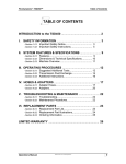
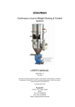
S-240 Series Power Extruder User Manual Version 2.2 Durham Geo Slope Indicator 2175 West Park Court Stone Mountain, GA 30087 USA Phone: 800-837-0864 or +1.770.465.7557 Fax: 770.465.7447 e-mail: [email protected] www.DurhamGeo.com Disclaimer Durham Geo-Enterprises, Inc. (including all affiliates to include its trade name of DGSI) makes no representations or warranties with respect to the contents hereof and specifically disclaim any implied warranties of merchantability or fitness for any particular purpose. Durham Geo Slope Indicator reserves the right to revise this publication and to make changes from time to time in its content without obligations to notify any person or organization of such revision or changes. IMPORTANT Before beginning installation procedures, these Installation and Operating Instructions should be studied carefully. The installation and operation should also be in accordance with local regulations and accepted codes of good practice. Information Record Model #: S-240 Sold By: ___________________ Date Purchased: _____________ Page 2 of 11 Table of Contents 2.0 Receiving page 5 5.0 Set-up Procedures page 6 5.1 Placement of the Base Unit page 6 5.1 Connecting Hydraulic Hoses page 6 5.2 Check oil Reservoir page 6 6.0 Operating Principles page 7 7.0 Accessories page 8 7.1 Leg Assembly page 8 7.2 Cylinder Bracket Arm page 8 7.3 2" Accessories page 8 8.0 Machine Maintenance page 9 Warranty Info. page 10 Parts lists page 11-13 Page 3 of 11 I M P O R T A N T S-240 EXTRUDER S A F E T Y I N S T R U C T I O N S IMPORTANT SAFETY INSTRUCTIONS Safety is a priority in the design of our remediation equipment. This manual highlights the areas that are important when you install and use this equipment. Following is a partial list of safety procedures: Wear chemically resistant clothing Wear safety goggles to protect your eyes Point air and discharge hoses away form your person and other personnel Turn off the air supply to the pump prior to service Avoid the pinch points during assembly and disassembly of the pumps Properly protect air supply and fluid discharge hoses from damage WARNING! Any electrical components used in an explosive atmosphere must be located in compliance with Chapter 5 of the National Electrical Code and any other local codes. This applies to electrically powered air compressors as well. Page 4 of 11 S-240 EXTRUDER RECEIVING To insure optimum performance it is strongly suggested that the operators read the manual prior to using the MVP Pumps. Failure to follow the installation and operation instructions may result in voiding the warranty of the equipment. 1.0 Models Covered This Manual covers the following DGSI models: S-240 2.0 Receiving Procedures 2.1 Damage in Transit This product has been packed to insure that it arrives at your location free from damage. Damage in shipping is rare but may happen so always check for evidence of damage or loss before signing for any shipment. Do not sign for any shipment with apparent damage until the carrier notes damage on the receipt and signs same. Do not discard original packing materials until equipment has been fully examined in operation. If damage to contents is evident, an examination and report by the transport agent must be requested. If damage is found after the carton is unpacked, notify the transport agent immediately to arrange an inspection and provide you necessary forms for filing a concealed damage report. Concealed damage must be reported to and inspected by the carrier within ten days. 3.0 4.0 Typical Tools for assembly Standard wrenches Unpacking Remove the S-240 from the packing crate. Check the contents you have received against the enclosed packing slip. Check all components for shipping damage and/or shortages. Notify Durham Geo Enterprises, Inc. immediately if damages or shortages are found. Page 5 of 11 S-240 EXTRUDER 5.0 Setup Procedures 5.1 Placement of Base Unit Place the Base Unit on a sturdy, level surface. Place the Hydraulic Power Unit at a location close to the Hydraulic Cylinder. 5.1 Connecting Hydraulic Hoses There are two hydraulic hoses supplied with the Power Extruder. Each hose is labeled to assist you in assembly. If for any reason the hoses are not labeled, remember that the manual hydraulic valve will work in either direction. Insure that one end of one hose is connected to the cylinder and the other end of the hose is connected to the hydraulic valve, repeat with the other hose. Connect the hoses and tighten them securely, insure that the hoses are not kinked or bent too sharply. The hydraulic pressure is quite high and the hoses will try to straighten out when loading. 5.2 Check Oil Reservoir Plug the hydraulic power unit in and turn the power switch on. Move the control valve handle towards the hydraulic cylinder until the hydraulic cylinder rod is fully retracted. Remove the oil cap and check the fluid level. Add hydraulic oil if needed (A good grade of hydraulic oil is required). Extend and retract the hydraulic cylinder several times and recheck the oil level. Add more oil if necessary. CAUTION: NEVER fill the reservoir with the cylinder rod extended. This will cause the reservoir to over flow when the ram is retracted. The unit is now ready to use. NOTE: During shipping and assembly air will be introduced into the hydraulic system, after approximately 2 weeks of use most of this air will be removed from the system, recheck the reservoir level. Fill if required. Check once per month thereafter. Page 6 of 11 S-240 EXTRUDER OPERATING PRINCIPLES 6.0 Principles of Operation 6.1 Operating Instructions Plug in unit and turn the switch to the on position. With the Piston in the fully retracted position, loosen the plastic knobs on the 3" clamp move the clamp bolts out of the way and remove the top support. Place a tube, containing a sample, onto the clamp. Make sure that the cutting edge of the sample tube is facing the hydraulic cylinder of the S-240. Move the tube forward until it shoulders against the Front tube support. Slide the clamp forward until it rests 1/4 of the way from the free end of the sample tube. Replace the top support and move the clamping bolts back into position and tighten both plastic knobs until the tube is held down securely. Move the hydraulic control valve handle to the extend position. Stop just before the piston reaches the end of the tube. Adjust the piston, if necessary, for proper entry into the tube. Note: There is a speed control valve on the nose end of the cylinder. (See page 12 detail B) Adjust as necessary to control the speed. Shutting this valve off will cause the relief valve to lift and will cause the oil to overheat. Avoid shutting this valve off. CAUTION: Keep fingers away from cutting edge of tube and piston. It may be necessary to clean out 1"-2" of material to facilitate piston entry. Continue extending piston until the sample is completely extruded from the tube. Retract piston fully. Loosen the plastic knobs on the 3" clamp and remove the clamp top. Remove the tube and replace the clamp top and tighten the plastic knobs. Turn off and unplug unit. Page 7 of 11 S-240 EXTRUDER 7.0 Accessories 7.1 Leg Assembly The leg assembly consists of two steel frame assemblies. The extruder base has 4 tapped holes on the bottom that will line up with the leg assembly. All necessary fasteners are included with the leg assembly kit. Place the base unit on the legs and insert the 1" long screws through the holes. Put the washers and nuts on and tighten everything securely. Remove the Vibration Isolators (Page 12 # 24) from the hydraulic pump. Set the hydraulic pump on the cross beam of both legs. Insert the 1" long screws into the 4 holes. Put the washers and the nuts on and tighten everything securely. CAUTION: The base unit of the S-240 is heavy and awkward to handle. To avoid injury, at least 2 people are needed to assemble base onto the leg assembly. 7.2 Cylinder Bracket Arm To support the weight of the hydraulic cylinder locate the turnbuckle bracket. A single ½-13 bolt is used to joint the two parts together the radius end of the turnbuckle simply rest in the angle bracket of the leg frame. (See figure on page 13) 7.3 Two inch Accessories The 2" Accessories are designed to allow you to extrude 2" O.D. tubes. The kit consists of a 2" Adapter Plate, 2" Holding Clamp, 2" Piston, four 1-1/2" long screws, and four 5/16" lock washers. To install these accessories, you must first remove the 5/16"-18 Socket head cap screws from the 3" piston. Remove the 3" piston and install the 2" piston. Insert the 2-5/16"-18 screws and tighten them. Remove the two 1" long screws and the two 5/16" lock washers holding the front support (Fig 1 #10) in place. Pull the front support from the tie rods. It is not necessary to remove the 3" holding clamp, simply slide it toward the cylinder and out of the way. Slide the 2" holding clamp onto the tie rods. Replace the front support back onto the tie rods and replace the screws and washers holding it in place. Place the 2" adapter plate on the cylinder side of the front support and line up the four holes on each of them. Make sure that the shoulder on the 2" adapter plate faces the hydraulic cylinder. Put the 5/16" lock washers on the 1-1/2" screws and insert the screws through the four holes in the front support and tighten them. Page 8 of 11 S-240 EXTRUDER MAINTENANCE 8.0 Machine Maintenance 8.1 Maintenance The S-240 is designed to be virtually maintenance free. The hydraulic cylinder rod should be kept clean and the oil reservoir might have to be topped up occasionally. CAUTION: Never use a wedge or any other type of stop when retracting the piston. Use of a wedge can result in a potentially hazardous situation that could cause damage to personnel or equipment. If you are having difficulty retracting the piston from the sample tube, check the following items: 1. Check that the tube is in line with the end of the extruder and that the piston is not in a bind due to misalignment. Correct any misalignment. 2. Check that the tube is free from damage that will prevent the piston from freely retracting. If your tubes are damaged, cylinder retraction may be facilitated by letting the piston float free in the tube by removing the retaining bolts that attach the piston to the piston rod. You will then need to manually remove the ram. 3. Be sure that you have the appropriate clamp in place and that the clamp is tight against the tube. Be careful not to over tighten the clamp, as this might damage the tube and prevent retraction. If you have any questions concerning the extruder, contact Durham Geo -Enterprises, Inc. @ 770-465-7557 OR 1-800-837-0864. Page 9 of 11 S-240 EXTRUDER LIMITED WARRANTY Durham Geo-Enterprises, Inc. / Slope Indicator (“DGSI”) warrants the products manufactured by DGSI to be free of defects of workmanship and material on a product basis. The products accompanied by this Warranty Statement are warranted for a period of ONE (1) YEAR from the date of delivery to the customer. If the customer is an authorized distributor of DGSI’s products, the warranty shall be for a period of ONE (1) YEAR from the date of delivery to the authorized distributor’s customer. The obligation of DGSI is hereafter limited to replacement or, at its option, repair of products returned to it, should DGSI's examination disclose, to its satisfaction, that the products were not free from defects. Products repaired or serviced by DGSI are warranted against defects in workmanship and materials for a period of 90 days, or the remainder of the original warranty period, whichever is greater. IN NO EVENT SHALL DGSI BE LIABLE FOR CONSEQUENTIAL OR SPECIAL DAMAGES, OR FOR INSTALLATION, ADJUSTMENT, LOST PROFITS OR OTHER COSTS WHICH MAY ARISE IN CONNECTION WITH SUCH PRODUCTS. THE APPLICABLE PRODUCT WARRANTY EXTENDS ONLY TO THE ORIGINAL CUSTOMER OF DGSI OR ITS AUTHORIZED DISTRIBUTOR, AS THE CASE MAY BE, AND IS EXPRESSLY IN LIEU OF ALL OTHER WARRANTIES, EXPRESS OR IMPLIED, WHETHER OF MERCHANTABILITY OR FITNESS FOR ANY PARTICULAR PURPOSE OR USE, AND OF ALL OTHER OBLIGATIONS AND LIABILITIES OF ANY KIND AND CHARACTER. EXCEPT FOR THE WARRANTY APPLICABLE TO THE SPECIFIC PRODUCT(S) PURCHASED, DGSI MAKES NO WARRANTY OF MERCHANTABILITY OF THE GOODS OR OF THE FITNESS OF THE GOODS FOR ANY PURPOSE. THERE ARE NO WARRANTIES WHICH EXTEND BEYOND THE DESCRIPTION ON THE FACE HEREOF. Any products, components or accessories that are not manufactured by DGSI and are supplied by other manufacturers are subject to their respective warranties. Certain products will carry their own warranties. For further assistance: Call 1-800-837-0864 (toll free) or +1 (770) 465-7557 E-mail [email protected] Page 10 of 11 S-240 EXTRUDER Do not over-tighten bolt Cylinder bracket detail Tension turnbuckle for cylinder support and alignment Remove angle shipping brackets before attaching to leg assembly Assemble legs with holes on the outside of frame Page 11 of 11 A B C D 2 B REV A 1 4 25 20 DETAIL B SCALE 0.40 : 1 B 4 REVISION HISTORY DESCRIPTION DATE REDESIGNED 1/27/2006 CHNG'D FLOW METER 7/5/2006 TO CORRECT SIDE 7 38 24 23 38 21 26 18 32 14 NOT SHOWN 31 15 10 5 9 6 11 27 B 38 B 3 28 4 2 3 2 APPROVED MFG QA NOTES: BOLTED ASSEMBLY-LEGS SHIPPED UNBOLTED HYDRAULIC LOAD SET FOR 10K IBS/FORCE SET PRESSURE RELIEF AT 1425 PSI DRAWN aphillips UNIT PAINTED SEMI-GLOSS BLACK CHECKED HYDRAULIC FLUID,AW 42 USED IN PUMP 22 12 13 FLOW DIRECTION FOR METERING VALVE FREE FLOW OPPOSITE DIRECTION ITEM 5 MOUNTING PLATE IS A PRESS FIT ONTO HYDRAULIC CYLINDER 3 33 1/27/2006 1/27/2006 1/27/2006 1 1 2 2 1 1 1 4 8 4 DGSI ANSI/ASME B18.2.1 3/8-16 UNC - 0.75 ANSI/ASME B18.2.1 3/8-16 UNC - 2.5 ANSI B18.2.2 - 3/8 - 16 ANSI/ASME B18.2.1 5/16-18 UNC - 1 ASTM F436 - 5/16 ANSI/ASME B18.2.1 5/16-18 UNC - 0.75 ANSI B18.8.2 - 3/16 x 3/4 Standard Duty 2151334 2151335 600894 250707 2153075 2153147 601935 601982 ANSI B18.2.2 - 5/16 - 18 ANSI B18.2.2 - 1 - 8 233801 164108 164107 231901 HF4MJ-4MB90 163601 ANSI B18.3 - 1/4 - 20 1/2 601957 233601 163501 163101 2152053 601932 601981 C SCALE DWG NO SIZE 1 OF 1 REV FITTING #4 MB X #4 MP FITTING 1/4 MP X #4 MJ FITTING #6 MB X #4 MJ 67" HOSE ASSEMBLY POWER CORD TOGGLE SWITCH HYDRAULIC CYLINDER LEVELING FOOT Hex Nut Hex Jam Nut SHEET 1 D A DESCRIPTION LEG WELDMENT TRAY WELDMENT PUMP MOUNTING WELDMENT METERING VALVE CYLINDER MOUNTING PLATE TIE ROD TUBE END SUPPORT PLATE 3" PISTON C Hexagon Socket Head Cap Screw SPIRAL RING 2336 LOWER CLAMP HALF UPPER CLAMP EYE BOLT KNOB HYDRAULIC PUMP # 4 HYDRAULIC FITTING ORING X JIC Hex Bolt - UNC (Regular Thread - Inch) Hex Bolt - UNC (Regular Thread - Inch) Hex Nut Hex Bolt - UNC (Regular Thread - Inch) Washer A B Hex Bolt - UNC (Regular Thread - Inch) Pin - Coiled Spring S-240 WITH S-24010 LEG ASSEM. TITLE 27 28 29 30 31 32 33 36 37 38 2 6 2 24 25 26 8 4 22 23 4 4 20 21 1 2 2 1 1 1 1 13 14 15 18 19 11 12 2 2 2 1 6 7 9 10 1 1 Parts List PART NUMBER QTY 2 601963 1 163901 1 601964 4 5 ITEM 1 2 3 30 19 1 A B C D 28 29 34 6 20 B 4 5 13 10 13 24 19 12 4 14 26 9 ITEM 4 MOUNTING PLATE IS A PRESS FIT ONTO HYDRAULIC CYLINDER ITEM 1 3 25 B 3 NOTES: BOLTED ASSEMBLY HYDRAULIC LOAD SET FOR 10K LBS/FORCE SET HYDRAULIC PRESSURE RELIEF AT 1425 PSI UNIT PAINTED SEMI GLOSS BLACK AW 42 HYDRAULIC FLUID USED IN PUMP 27 34 11 21 23 METERED FLOW DIRECTION FREE FLOW OPPOSITE DIRECTION DETAIL B SCALE 0.60 : 1 3 4 17 15 31 1 2 APPROVED MFG QA CHECKED aphillips DRAWN 30 2 2 32 2/2/2006 2/2/2006 2/2/2006 16 2 8 4 DGSI ANSI B18.22.1 - 3/8 narrow - Type A ANSI B18.2.2 - 1 - 8 ANSI/ASME B18.2.1 3/8-16 UNC - 1 ASME B18.21.1 - 3/8 Regular. Carbon Steel 2153075 2153147 601956 233801 164108 164107 163601 231901 HF4MJ-4MB90 ANSI/ASME B18.2.1 3/8-16 UNC - 2.5 ANSI B18.2.2 - 3/8 - 16 ANSI B18.8.2 - 3/16 x 3/4 Standard Duty 2151334 2151335 600894 250707 187629 ANSI B18.2.2 - 1/4 - 20 ASTM F436 - 1/4 601958 ANSI B18.3 - 1/4 - 20 1/2 601957 233601 163501 163101 2152053 601932 601996 C SCALE DWG NO SIZE S-240 TOP LEVEL TITLE 34 1 1 1 1 30 31 32 33 4 29 5 1 1 2 2 4 4 4 4 20 21 22 23 24 25 26 27 28 4 2 1 2 2 1 1 1 4 18 19 11 12 13 14 15 16 17 1 1 2 1 5 6 9 10 1 1 1 Hex Jam Nut OF 1 A REV A FITTING #4 MB X #4 MP FITTING 1/4 MP X #4 MJ FITTING #6 MB X #4 MJ 67" HOSE ASSEMBLY VIBRATION ISOLATOR Hex Jam Nut Washer A B ANGLE FOOT BRACKET Hex Bolt - UNC (Regular Thread - Inch) Helical Spring Lock Washer POWER CORD TOGGLE SWITCH CYLINDER MOUNTING BRACKET Washer A Hex Bolt - UNC (Regular Thread - Inch) Hex Nut Pin - Coiled Spring SHEET 1 D DESCRIPTION HYDRAULIC CYLINDER PUMP MOUNTING WELDMENT METERING VALVE CYLINDER MOUNTING PLATE TIE ROD TUBE END SUPPORT PLATE Hexagon Socket Head Cap Screw SPIRAL RING 2336 LOWER CLAMP HALF C UPPER CLAMP EYE BOLT KNOB 3" PISTON HYDRAULIC PUMP 1 REVISION HISTORY DESCRIPTION DATE DRAWN AND 2/2/2006 RELEASED CHG'D HYD FLOW VALVE TO 7/5/2006 CORRECT SIDE. Parts List PART NUMBER QTY 1 601935 1 601964 3 4 ITEM 1 2 B A REV