1
US 20020143410A1
(19) United States
(12) Patent Application Publication (10) Pub. N0.: US 2002/0143410 A1
(43) Pub. Date:
Yance et al.
(54)
METHOD OF CONTROLLING A
MICROCOMPUTER AFTER POWER
SHUTDOWN
Oct. 3, 2002
Publication Classi?cation
(51)
Int. c1.7 ........................ .. G05B 11/01; G05B 19/18;
(52)
US. Cl. ................. .. 700/11; 700/12; 700/2; 700/21;
G05B 9/02
(75) Inventors: Llewellyn Yance; Singapore (SG);
Satoshi Endo; Osaka (JP)
700/79
Correspondence Address:
(57)
GREENBLUM & BERNSTEIN, P.L.C.
A method for controlling a microcomputer is provided. The
1941 ROLAND CLARKE PLACE
microcomputer is operable Without completely expending
RESTON, VA 20191 (US)
(73)
(22)
(30)
poWer of backup poWer supply When main poWer is shut
doWn. During the poWer shutdown; the microcomputer is
Assignee: MATSUSHITA ELECTRIC INDUS
connected to a capacitor as a backup poWer device Which
TRIAL co., Ltd.; Osaka (JP)
(21) Appl. No.:
Filed:
ABSTRACT
supplies small amount of current for a short period. Thus, the
microcomputer can execute softWare for a given period. By
changing an operation mode of the microcomputer from
10/025,553
high speed mode to low speed mode, poWer consumption of
Dec. 26, 2001
the microcomputer can be signi?cantly reduced. The method
Foreign Application Priority Data
Dec. 27; 2000
(JP) .................................... .. 2000397543
uses softWare to suppress poWer consumption of the micro
computer to the minimum and to measure a duration time of
poWer shutdoWn.
START OF
OPERATION
NORMAL OPERATION
IS
THERE ANY POSSIBILITY
S12
FOR POWER’) SHUTDOWN
YES
. s13
MICROCOMPUTER MAKES
ARRANGEMENTS FOR THE POWER SHUTDOWN
IS
POWER SHUTDOWN
DETECTED ?
YES
_
As THE R EAL
IM': CLOCK BEEN SET-UP FOR
OPERATION ‘PRIOR TO A POWER
SHUTDOWN?
'
s17
S15
‘ S16
SWITCH TO
STOP MODE
SWITCH TO 10w SPEED MODE
STOP HIGH SPEED OSCILLATION
“PI
s18
sEwsEcoNn TIMER INTERHUPTS
WAIT FOR THE INTERRUPTS
IS THE POWER
SUPPLY RECOVERED ?
NO
IS THE
S
INTERRUPT OF I-SEGOND TIMER
O
ENERATED ?
I
YES
HAVE 3 SECONDS PASSED 7
I YES
CLEAR THE CLOCK COUNTS
SWITCH TO STOP MODE
S22
Patent Application Publication
Oct. 3, 2002 Sheet 1 0f 4
m259$.2085%8
X5I2SQ6w5:8iJmAH LArEE:r2%0@58m2g NTm528052
ma
2%
m
4
m
_
2;
m
"
at
N
US 2002/0143410 A1
Patent Application Publication
Fig.2
Oct. 3, 2002 Sheet 2 0f 4
US 2002/0143410 A1
START OF
OPERATION
S1 1
NORMAL OPERATION
IS
THERE ANY POSSIBILITY
S12
FOR POWER? SHUTDOWN
YES
I
S13
MICROCOMPUTER MAKES
ARRANGEMENTS FOR THE POWER SHUTDOWN
IS
POWER SHUTDOWN
S14
DETECTED ?
.
YES
AS THE REAL
IME CLOCK BEEN SET-UP FOR
OPERATION PRIOR TO A POWER
SHUTDOWN ?
“
S17
SWITCH TO
STOP MODE
S15
S16
SWITCH TO LOW SPEED MODE
STOP HIGH SPEED OSCILLATION
SI 8
SETI-SECOND TIMER INTERRUPTS
WAIT FOR THE INTERRUPTS
‘I
IS THE POWER
, S19
SUPPLY RECOVERED?
NO
IS THE
INTERRUPT OF I~SECOND TIMER
ENERATED ?
S
.
YES
HAVE 3 SECONDS PASSED 7
I YES
CLEAR THE CLOCK COUNTS
SWITCH TO STOP MODE
8 21
S22
Patent Application Publication
Oct. 3, 2002 Sheet 3 0f 4
US 2002/0143410 A1
m$E59628
gag.
2ED625émm
Patent Application Publication
Fig.4
Oct. 3, 2002 Sheet 4 0f 4
US 2002/0143410 A1
Oct. 3, 2002
US 2002/0143410 A1
METHOD OF CONTROLLING A
MICROCOMPUTER AFTER POWER SHUTDOWN
BACKGROUND OF THE INVENTION
[0001] This invention relates to a microcomputer system
Which employs a limited backup supply resource When
poWer failure of the main poWer supply occurs, and Which
retains a content of a backup memory for a certain period of
time.
DESCRIPTION OF THE BACKGROUND ART
SUMMARY OF THE INVENTION
[0010] The present invention overcomes primary disad
vantages of the system With the above-mentioned hardWare
based timing circuit. Thus it is an object of the present
invention to keep a real-time clock in the system updated
even after a poWer shutdoWn. This system can keep the
real-time clock accurately updated With the long-battery
backup life even if it stays in poWer shutdoWn for a long
time. This can be achieved because the method of the present
invention uses only softWare to measure the time spent by
the microcomputer during poWer shutdoWn.
[0002] A microcomputer system generally employs clock
[0011] The microcomputer system of the present invention
counts (i,e, a real-time clock) to shoW the current day and
time. Such a real-time clock is also used for operations of
functions in the system Which requires to refer to time
information.
includes three devices: a counter IC, a microcomputer IC
and a clock IC. The microcomputer IC and the clock IC stop
their functions When poWer shutdoWn occurs. On the other
[0003] HoWever, the system With a real-time clock is
prone to be affected easily the accuracy of the real-time
clock When a short poWer interruption (eg a momentary
poWer shutdoWn) occurs. In some systems, When a short
poWer shutdoWn occurs, the real-time clock is immediately
cleared and disabled upon resumption of poWer. Causes of
momentary poWer shutdoWns can range from an accidental
unplugging of the system from AC to ?uctuations in the AC
poWer line.
[0004]
This becomes an annoyance to a user since he/she
alWays needs to re-enable and adjust the real time clock
every time a short poWer shutdoWn occurs.
[0005]
In order to minimiZe such annoyance in the use of
the real-time clock, Whenever poWer in the system is shut
doWn and if the shutdoWn is momentary, the microcomputer
of the system should not clear the real-time clock. To
achieve such an operation, it is a problem hoW to determine
Whether a shutdoWn of the system poWer is momentary or
not When the shutdoWn occurs.
[0006] One eXample to solve the problem is that a CR
timer is provided to measure hoW long the microcomputer
system is in poWer shutdoWn. If the system shutdoWns for
more than, for eXample, 3 seconds, the real time clock is
cleared and initialiZed. This is because that the system can
avoid excessive time delay brought by stopping the real time
clock resulted from a setting to a stop mode of the micro
computer system during poWer shutdoWn in Which clock
oscillation is stopped.
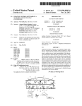
[0007] FIG. 4 is a circuit diagram of an arrangement of a
conventional hardWare-based CR timer. The conventional
hand, the counter IC continues counting by means of poWer
supplied from a backup battery. When the poWer is recov
ered, the microcomputer obtains a count value of the counter
IC to update clock counts.
[0012] According to the present invention, a method for
controlling a microcomputer in microcomputer system With
a high speed operation mode and a loW speed operation
mode in Which operations of the microcomputer is sloWer
than in the high speed operation mode is provided. The
microcomputer system including a clock operable in the
high and the loW speed operation mode and a backup poWer
supply for supplying the clock With poWer for a predeter
mined time. The method includes steps of: detecting poWer
shutdown; changing the high speed operation mode to the
loW speed operation mode; determining Whether the poWer
shutdoWn is recovered Within a given time period; and
setting the high speed operation mode When the poWer
shutdoWn is determined to be recovered. Thus, the above
mentioned object can be achieved.
[0013]
As one aspect of the invention, the method includes
steps of detecting poWer shutdoWn; changing the high speed
operation mode to the loW speed operation mode; periodi
cally determining Whether the poWer shutdoWn is recovered
Within a ?rst given time period; setting the high speed
operation mode When the poWer shutdoWn is determined to
be recovered; and setting the microcomputer to a stop
operation mode to stop operations unless the poWer shut
doWn is recovered Within the second given time period
Which is longer than the ?rst given time period. Thus, the
above-mentioned object can be achieved.
[0014] As another aspect of the invention, the method
includes steps of detecting poWer shutdoWn; checking
hardWare CR timer includes microcomputer I/O ports 41, a
resistor 42, a diode 43, a capacitor 44.
Whether the clock is set; setting the microcomputer to a stop
operation mode to stop operations unless the clock is set;
[0008]
changing the high speed operation mode to the loW speed
The conventional hardWare-based CR timer pre
sents a number of disadvantages. Firstly, high quality, that is,
operation mode When the clock is set; periodically deter
expensive components are required to obtain accurate hard
Ware-based CR timer, since accuracy of the hardWare-based
CR timer depends on tolerance of the components. Thus,
cost of the components add up to the overall material cost of
the system. Note that the functional value of this circuit does
not justify its cost, since the CR timer circuit is used only for
about a feW seconds every time the system is shutdoWn.
mining Whether the poWer shutdoWn is recovered Within a
[0009]
Secondly, the number of devices that the micro
?rst given time period; setting the high speed operation
mode When the poWer shutdoWn is determined to be recov
ered; and setting the microcomputer to the stop operation
mode unless the poWer shutdoWn is recovered Within the
second given time period Which is longer than the ?rst given
time period. Accordingly, the above-mentioned object can
be achieved.
computer can directly control are reduced because of a need
[0015] According to the present invention, microcomputer
to allocate a microcomputer I/O port for the CR timer.
is supplied With poWer by a backup capacitor as a backup
Oct. 3, 2002
US 2002/0143410 A1
power supply With small amount of current for a short period
during power shutdown of the poWer supply. Therefore,
TABLE 1-continued
microcomputer can continue to execute software for a given
period. By transferring operation mode of the microcom
puter from High Speed Mode to loW speed mode, poWer
consumption is signi?cantly reduced. It is further costly
advantageous that present invention requires no input/output
ports of the microcomputer.
[0016] Advantages of the method according to the present
invention are as folloWs: The neW method eliminates the
need for adding a hardWare-based CR timer in the system
thereby the overall cost can be brought doWn. The neW
method eliminates the need to allocate microcomputer I/O
ports once the hardWare-based CR timer has been eliminated
from the system thereby the system does not need to use the
microcomputer I/O ports. Therefore, the present invention is
Operating Condition
Typical
Stop Mode:
0.1 uA
Maximum
1 uA
All Oscillations Stopped
Waiting for interrupt
M3819 series PoWer Source Current(Icc)
Taken from page 56, 3819 family user’s manual
[0025]
As seen from the table above, there is a great
difference in consumption current of the microcomputer.
More speci?cally, the current consumption of the micro
computer operating at high speed mode is about 100 times
as large as that of the microcomputer operating at loW speed
mode. It can also be seen from the table that there is only a
costly advantageous.
small difference in current consumption When the micro
computer operates in loW speed mode or stop mode as
[0017] The present invention utiliZes microcomputer’s
compared to high speed mode.
crystal oscillator as a time reference so that timing accuracy
[0026] In the present invention, CR timer hardWare is not
used in a circuit, thus the microcomputer is responsible for
can be consistent.
measuring hoW long the system is unplugged. This requires
BRIEF DESCRIPTION OF THE DRAWINGS
the microcomputer to continue functioning at least about 3
[0018] These and other objects and features of the present
invention Will become clear from the folloWing description
taken in conjunction With the preferred embodiments thereof
With reference to the accompanying draWings, in Which:
seconds after a poWer shutdoWn is detected. Systems With a
[0019]
FIG. 1 is a timing chart of the operation of a
microcomputer according to the present invention.
[0020]
FIG. 2 is a ?oWchart of operating sequence of the
microcomputer according to the present invention.
[0021]
FIG. 3 is a diagram of a speci?c arrangements of
signal generation circuit 30 for supplying the AC DET signal
and a voltage (VDD).
microcomputer usually employ a 24-hour real-time clock to
keep track of the current time in a day.
[0027] FIG. 1 is a timing chart of the operation of a
microcomputer according to the present invention. During
normal operation, the microcomputer detects the rising or
falling edge of the signal at AC DET as shoWn in FIG. 1. If
no edge is detected for more than 2.5 cycles of 50 HZ (5
OmS), it is con?rmed that the AC poWer supply Was
removed from the system and a poWer shutdoWn sequence
must be executed. In other Words, the microcomputer in
normal operation mode With high speed oscillation transfers
to an operation mode at the time of a poWer shutdoWn after
[0022] FIG. 4 is a circuit diagram of an arrangement of a
conventional hardWare-based CR timer.
50 ms has passed since last edge of an AC DET signal has
detected.
[0028] In the operation mode at the time of poWer shut
DETAILED DESCRIPTION OF THE
PREFERRED EMBODIMENTS
doWn, the oscillation is sloWer than in the normal operation
[0023]
Some embodiments of the present invention Will be
described referring to the accompanying draWings. Same
functional components are denoted by same numerals
throughout the draWings.
[0024]
CMOS microcomputers consume less poWer, as
operating speed of them becomes sloWer. For example,
poWer current spec of Mitsubishi 3819 microcomputers is
shoWn in table 1.
mode. A voltage applied to the microcomputer is gradually
loWered after no edge of the AC DET signal has detected. In
addition, the microcomputer stops oscillating after 3000 ms
(i.e. 3 seconds) has passed since the microcomputer trans
ferred to loW speed mode, at the time of Which the voltage
applied to the microcomputer becomes the loWest.
[0029] FolloWing are the exemplary sequence of the
operation. FIG. 2 is a ?oWchart of operating sequence of the
microcomputer according to the present invention. At the
normal operation, the microcomputer operates in high speed
mode (step S11). At the same time, Whether possibility of
TABLE 1
poWer shutdoWn occurs or not is continuously determined
Operating Condition
Typical
Maximum
High Speed Mode:
7.5 mA
15 mA
60 uA
200 uA
20 uA
40 uA
8.4 MHZ
Executing Instructions
LoW Speed Mode:
32 KHZ
Executing Instructions
LoW Speed Mode:
32 KHZ
WAIT state
(Wait for INT)
(step S12). In the case that there is no possibility for the
poWer shutdoWn (i.e. in the case that poWer shutdoWn has
not occurred), the microcomputer continues normal opera
tion (“NO” in step S12). In the case that the possibility of the
poWer shutdoWn exists (“YES” in step S12), the microcom
puter makes arrangements for the poWer shutdoWn (step
S13). For example, the arrangements include setting micro
computer I/O ports and de-energiZing circumferential cir
cuits against poWer shutdoWn.
[0030] PoWer ShutdoWn detection for the microcomputer
system is performed by detecting intermittent pulses coming
Oct. 3, 2002
US 2002/0143410 A1
from the AC power line (for example, 50 HZ). Intermittent
clears the clock counts and transfers to stop mode in the end
pulses are detected based on the AC DET signal Which is
supplied to one input port (AC DET), after rectifying and
(step S22). Since all the oscillations are stopped in the stop
mode, current from capacitor poWer supply can be sup
reducing the amplitude of the poWer supply line to a
pressed to the minimum. In such a loW poWer consumption
predetermined level, thus magnitude of the AC DET signal
becomes suitable to input to the microcomputer. A speci?c
arrangement of a circuit for generating the AC DET signal
is mentioned later With reference to FIG. 3.
[0031] During normal operation, the microcomputer
state, data stored in RAM can be retained for more than 2
Weeks by means of electricity only left in the backup
capacitor. Detection of shutdoWn time is stopped afterWards.
[0036]
FIG. 3 is a diagram of a speci?c arrangements of
signal generation circuit 30 for supplying the AC DET signal
detects a rising or a falling edge of the AC DET signal. If no
and a voltage. FIG. 3 also illustrates Microcomputer 36 as
edge is detected for more than 2.5 cycles of 50 HZ (5 OmS),
Well as signal generation circuit 30. The AC DET (SYNC)
it is con?rmed that the AC poWer supply is removed from
the system and a poWer shutdoWn sequence must be
signal is produced by converting a voltage from AC poWer
supply using a transformer and by adjusting the signal
executed (“YES” of step S14). If an edge is detected Within
voltage to be constant via recti?er 32 and Zener diode 33.
5 OmS again, the microcomputer returns to normal opera
The voltage applied to microcomputer 36 Which is also
tion mode (“NO” of step S14).
referred to as microcomputer Vdd is output after a voltage
[0032]
from AC poWer supply is converted by using a transformer
and adjusted via recti?er 32 and regulator 34.
In the case that the real time clock has not been
set-up for operation prior to a poWer shutdoWn (“NO” of
step S15), the microcomputer is set to stop mode to set the
port for poWer shutdoWn (step S17), since processing opera
tions such as counting clocks described later is not needed.
According to such operations, time for retaining memory
content by a backup capacitor can be extended. HoWever, in
the case that the real time clock has been set-up for operation
prior to a poWer shutdoWn (“YES” of step S15), When poWer
shutdoWn (AC off) is detected, oscillation of the microcom
puter is sWitched from high speed mode to loW speed mode
to result in a signi?cant reduction in poWer consumption
(step S16). This means that the microcomputer can still
operate by means of supply from the backup capacitor for a
short time Without completely discharging the backup
poWer.
[0033]
Once the system is in the loW speed mode, an
internal timer is set to generate an interrupt in every second
(step S18). By executing a WAIT instruction after setting up
the 1-second timer, the microcomputer is kept in sleep state
While Waiting for a 1-second interrupt to be generated.
Current consumption of the microcomputer during Waiting
[0037] Backup capacitor 35 is employed to provide micro
computer 36 With small amount of current for a short period
during poWer failure of the poWer supply. Therefore, in the
case the poWer supply is removed from the system, micro
computer 36 can continue to execute softWare for a given
period. Note that microcomputer 36 includes tWo types of
oscillators: a high speed oscillator 37 and a loW speed
oscillator 38. High speed oscillator 37 is utiliZed When
microcomputer 36 operates in high speed mode. LoW speed
oscillator 38 is utiliZed When microcomputer 36 operates in
loW speed mode.
[0038] In the above description, microcomputer transfers
to loW speed mode after 5 OmS has passed since last edge
of AC DET signal Was detected, and transfers to stop mode
after 3 seconds has further passed. HoWever, those Who
skilled in the art may change the above values properly.
[0039] The invention being thus described, it Will be
obvious that the same may be varied in many Ways. Such
variations are not to be regarded as a departure from the
for the interruption is reduced to be maximum 60 MA.
During in WAIT Mode, Whether the poWer supply is recov
ered or not is monitored (step S19).
spirit and scope of the invention, and all such modi?cations
[0034] When the system poWer supply is recovered during
the microcomputer is Waiting for the interruption (“YES” of
[0040] The present disclosure relates to subject matter
contained in priority Japanese Patent Application No. 2000
as Would be obvious to one skilled in the are intended to be
included Within the scope of the folloWing claims.
step S19), the microcomputer quickly changes loW speed
397543, ?led on Dec. 27, 2000, the contents of Which is
mode to high speed mode and returns to the normal opera
herein expressly incorporated by reference in its entirety.
tion after resetting. On the other hand, When the system
poWer supply is not recovered, Whether the 1-second timer
generates the interrupt or not is further determined (step
S20). When the 1-second timer generates the interrupt, the
microcomputer is activated to operate in loW speed mode.
Note that even if the 1-second timer generates the interrupt,
in the case 3 seconds has not passed, the microcomputer is
again set to Wait for the interrupt from the 1-second timer
during the operation to be in WAIT Mode so as to suppress
the poWer consumption of the microcomputer. During WAIT
Mode, current consumption is reduced and at the same time,
data stored in RAM is never affected as long as poWer
supply voltage (Vdd) of the microcomputer is kept above the
rated levels. Note that the system may include one or more
volatile memories to hold the time spent by the microcom
puter during poWer shutdoWn.
[0035] When the system poWer supply has been shutdoWn
yet after 3 seconds passed (step S21), the microcomputer
What is claimed is:
1. A method for controlling a microcomputer in micro
computer system With a high speed operation mode and a
loW speed operation mode in Which operation speed of the
microcomputer is sloWer than that of the high speed opera
tion mode, said microcomputer system including a clock
operable in the high and the loW speed operation mode and
a backup poWer supply for supplying the clock With poWer
for a predetermined time, said method comprising steps of:
detecting poWer shutdoWn;
changing the high speed operation mode to the loW speed
operation mode;
determining Whether the poWer shutdoWn is recovered
Within a given time period; and
Oct. 3, 2002
US 2002/0143410 A1
setting the high speed operation mode When the power
shutdown is determined to be recovered.
2. The method for controlling a microcomputer according
to claim 1, Wherein the clock measures the given time period
in the loW speed operation mode.
3. The method for controlling a microcomputer according
to claim 1, further comprises a step of setting the micro
computer to a stop operation mode to stop operations unless
the poWer shutdoWn is recovered Within the given time
period.
4. The method for controlling a microcomputer according
to claim 1, Wherein the microcomputer system further com
prises a volatile memory for storing a value representing a
time period Which the microcomputer measures during
poWer shutdoWn.
5. A method for controlling a microcomputer in micro
computer system With a high speed operation mode and a
loW speed operation mode in Which operations of the
microcomputer is sloWer than that of the high speed opera
tion mode, said microcomputer system including a clock
7. The method for controlling a microcomputer according
to claim 5, Wherein the microcomputer system further com
prises a volatile memory for storing a value representing a
time period Which the microcomputer measures during
poWer shutdoWn.
8. A method for controlling a microcomputer in micro
computer system With a high speed operation mode and a
loW speed operation mode in Which operations of the
microcomputer is sloWer than that of the high speed opera
tion mode, said microcomputer system including a clock
operable in the high and the loW speed operation mode and
a backup poWer supply for supplying the clock With poWer
for a predetermined time, said method comprising steps of:
detecting poWer shutdoWn;
checking Whether the clock is set;
setting the microcomputer to a stop operation mode to
stop operations unless the clock is set;
operable in the high and the loW speed operation mode and
a backup poWer supply for supplying the clock With poWer
for a predetermined time, said method comprising steps of:
changing the high speed operation mode to the loW speed
detecting poWer shutdoWn;
changing the high speed operation mode to the loW speed
periodically determining Whether the poWer shutdoWn is
recovered Within a ?rst given time period;
operation mode;
periodically determining Whether the poWer shutdoWn is
recovered Within a ?rst given time period;
setting the high speed operation mode When the poWer
shutdoWn is determined to be recovered; and
setting the microcomputer to a stop operation mode to
stop operations unless the poWer shutdoWn is recovered
Within the second given time period Which is longer
than the ?rst given time period.
6. The method for controlling a microcomputer according
to claim 5, the second given time period is set to be longer
than the ?rst given time period by substantially an integral
multiple.
operation mode When the clock is set;
setting the high speed operation mode When the poWer
shutdoWn is determined to be recovered; and
setting the microcomputer to the stop operation mode
unless the poWer shutdoWn is recovered Within the
second given time period Which is longer than the ?rst
given time period.
9. The method for controlling a microcomputer according
to claim 8, Wherein the microcomputer system further com
prises a volatile memory for storing a value representing a
time period Which the microcomputer measures during
poWer shutdoWn.