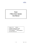
1
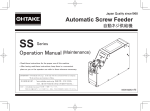
Automatic Screw Hopper 自動ネジ補給機 $XWRPDWLF6FUHZ)HHGHU 䠭䠱䠥䠟䠤䠡䠮 Floor Type NEJIKURA 䠪䠯䠮䠥㻌㼀㼥㼜㼑 (SR-80 ・ NJ-80 ・ NJ-80F) Operation Manual 1RGTCVKQP/CPWCN 4GCFVJGUGKPUVTWEVKQPUHQTVJGRTQRGTWUGQHVJKUOCEJKPG ・ Read these instructions for the proper use of this machine. #HVGTJCXKPITGCFVJGUGKPUVTWEVKQPUMGGRVJGOKPCEQPXGPKGPVRNCEGUQ[QW ・QTVJGQRGTCVQTECPTGHGTVQVJGOYJGPGXGTPGEGUUCT[ After having read these instructions, keep them in a convenient place so you or the operator can refer to them whenever necessary. ATTENTION : www.ohtake-root.co.jp is the only web site associated with our company. We do not have any branches in China. ྛ栦ᐈ実ὀព㸸ࠕwww.ohtake-root.co.jp ᩎྖ၏୍ⓗᐁ᪉⨒❰㸪 ┠๓㸪ᩎྖᅾ୰ᅜἐ᭷≆⢬ᡤ宻ⓗ୰ᅜᐁ⨒ࠋ ࠖ ὀព㸟㸸www.ohtake-root.co.jp ࡀᙜ♫၏୍ࡢ HP ࢻࣞࢫ࡛ࡍࠋ ᘢ♫ࡢྡࢆ㦄ࡿഇࢧࢺࡈὀពୗࡉ࠸ࠋ⌧ᅾࠊᙜ♫ࡣ୰ᅜᅜෆᨭᗑࡣࡈࡊ࠸ࡲࡏࢇࠋ 16,50$( ONF1MA01 Contents 6) Specifications・・・・・・・・・・ P 15 1) Before you start・・・・・・・・・ P3 7) Assembly Dimensions・・・・・・・ P 16 2) Note on operation・・・・・・・・ P3 8) Warranty ・・・・・・・・・・・ P 19 3) Identifying each part・・・・・・・ P5 9) How to setup Nejikura with FM-36・ P 20 4) Adjusting & checking before use ・ P8 Power Input:AC100V 50/60Hz AC adapter 5) Troubleshooting ・・・・・・ P 12 (linear type) Output:DC12V 500mA To use the unit safely, be sure to follow the instructions. NJ-80,NJ-80F: 142(W)×191(D)×188(H) ( Dimensions SR-80: 142(W)×191(D)×189~198(H) (m ●The following marks specify the extent of hazard and hazard evasion. WARNING CAUTION Weight Approx. 2.9Kg This mark implies possibility of serious injury caused by the wrong handling in disregard of the instructions. Operation Manual 1 copy 1 unit This mark implies possibility of the accidental injury or physical damage causedAC by Adapter the wrong handling in disregard Screw spill-out prevention cover 1 unit of the instructions. Following 【Below, only for NJ-80F】 accessories Stand 1 unit Weld bolt 2 unit Prohibited operations. Screws to fix the stand (M2.6×5mm) 3 piece ●Other precaution marks Be sure to follow the instructions. Never disassemble or repair Unplug the power source from a wall outlet Do not touch Compatible screw size Compatible screw lengths Screw sensor M2.0~M6.0 Up to 15 mm Pphotometric sensor Screw capacity Approx. 800cc Possible number M2.3×5 / About 20,000 screws of screw stored M3.0×6 / About 5,600 screws 1) Before you operationg the machine Check whether it conforms to the feeder with which the part number of Nejikura. Nejikura Type Corresponding Automatic Screw Feeder Check that the following accessories are supplied with Nejikura: SR-80 NSB/NSR/NSBI/NSRI Series * Instruction Manual 1 copy * AC Adapter 1 unit NJ-80 NJ/NJR Series * Screw retaining Cover 1 unit NJ-80F FM-36/FME-36 Series 【Only for NJ-80F:】 * Stand 1 unit * Weld bolt 2 unit * Screws to fix the stand (M2.6×5) 3 unit Nejikura Type Corresponding Automatic Screw Feeder *For this machines purchased outside of Japan, no adaptor will be supplied with the feeder. Please purchase separate NSB/NSR/NSBI/NSRI SR-80 adapter with quivalent output specification as required. NSB²/NSR²/NSBI²/NSRI² - 1 - NJ-80 NJ/NJR NJ²/NJR² 2) Note on operation In case of trouble WARNING If you run into any trouble using the unit, turn off the power switch and unplug the AC power adapter. If you keep using it without corrections, it may cause electric shock, injury or fire. Contact your dealer immediately. Installation CAUTION WARNING Setup the unit on the flat and stable surface. Unstable installation can cause falling, overturning, or breakdown of the unit and cause injury. Do not operate the unit in the place where an flammable material or explosive gas may be present. Screws not be used Do not feed the nonstandard screws or screws stained with oil or dust. Rotor Never touch the rotor while main power is turned on.It may cause serious injury. WARNING Screw inlet and outlet Never insert your fingers into the screw inlet and outlet while the power is turned on. WARNING Upper cover CAUTION Do not remove the upper cover. If a screw drops inside the machine, it would clog the rotation and may cause breakdown of unit. After work and out of operation When the unit is not used for a long time, unplug the power adaptor from wall outlet. - 2 - 3) Name of components DC input jack Rotor Screw inlet cover Upper cover Screw gate adjusting plate ねじ蔵 NJI KURA SR‑80 Proecision Screw Hopper Screw remnant sensor ② ③ ④ Auto/Manual Manual LOW Sensor HIGHT ⑤ Height adjuster (only for SR-80) (This illustration above is for SR-80 . For NJ-80, NJ-80F, the location for DC-juck and sensor accessories will be on opposite side.) - 3 - Screw Lamp ① Power MAX Time MIN ⑥ Switch Function ① Power:Power source switch (red LED turns on) ② Auto/Manual:A changeover switch for the automatic and manual modes (green LED turns on when it is in the automatic mode and off in manual mode.) ③ Manual:A switch to supply the screws with the manual mode. When it is in the manual mode, press the blue switch to supply the screws to Automatic Screw Feeder. This switch is unavailable in the automatic mode. ④ Screw Lamp:LED to show the empty screw in Automatic Screw Feeder. ⑤ Sensor (detecting screw amount in feeder):An adjuster for the sensor responding from the amount of screws in Automatic Screw Feeder. LED turns on when the sensor functions. ⑥ Time (adjusting screw supply amount):An adjuster to regulate the amount of screw to be supplied. It adjusts the rotating time of rotor. ■ Hopper capacity of Nejikura The hopper of Nejikura can be filled with the screws up to its brim (See photo 1.) ■ Screw gate adjusting plate If the screw clogs at the screw gate of rotor, lower the screw gate adjusting plate. (See illustration 1.) WARNING Illustration 1 When you adjust the screw gate adjusting plate, be sure to unplug the power source. Adjusting screws for screw gate adjusting plate. ねじ蔵 Auto/Manual Manual LOW Sensor HIGHT - 4 - NEJI KURA NJ‑80 Precision Screw Hopper Screw Lamp Power MAX Time MIN Photo 1 4) Adjusting & checking before use. 1. Adjusting screw sensor. Scooper To keep an appropriate amount of screws in Automatic Screw Feeder, adjust the screw sensor. (See illustration 2.) How to adjust 1) Empty all the screw in Automatic Screw Feeder and turn on power switch. 2) Turn on Auto/Manual Changeover Switch of Nejikura and identify that the green lamp turned on. 3) Turn the adjuster of screw sensor with a Philips screwdriver from MIN to MAX direction slowly and stop turning at the point where the LED starts to blink. 4) After the above adjustment, operate Automatic Screw Feeder and identify that LED lamp blinks in response to up and down movement of the scooper of Automatic Screw Feeder. ねじ蔵 NJI KURA SR‑80 Proecision Screw Hopper Auto/Manual Manual Screw Lamp Power LOW MAX Time Sensor MIN HIGHT → Illustration 2 2. Adjusting rotor (impeller) rotating time. To supply appropriate screws to Automatic Screw Feeder, set the rotating time of rotor with the timer. (See illustration 3.) It will be easy to adjust the rotor (impeller) as seeing it through the screw supply port of Automatic Screw Feeder (See illustration 4.) B A ねじ蔵 NJI KURA SR‑80 Proecision Screw Hopper NSR Auto/Manual Manual LOW Sensor HIGHT Screw Lamp Power MAX → How to adjust 1) Turn the timer adjuster from MIN to MAX direction slowly. 2) The standard adjustment is to make the impeller moves clockwise(from A to B as shown in illu. 4.) per turn. Thereafter, make the minor adjustment according to the actual flow of screws. Note: for the long size screws, set the rotating distance wider than that of the standard. - 5 - Time MIN Illustration 3 Illustration 4 3. Minor adjustment 1) After the adjustments of screw sensor and rotating time specified in paragraphs 1 and 2, fill Nejikura with the screws. 2) Operate the unit and check how it works. Adjust the screw sensor and timer if it is necessary. It is recommended to set the amount of screw in Automatic Screw Feeder small to avoid the clogging of screws. Appropriate amount of screw in Automatic Screw Feeder 4. Screw containing cover When mount the screw containing cover, loose the screw of two height adjustment plates. (Refer to photo 1) Although a cover is inserted from this side of an Automatic Screw Feeder, the adjustment plate of the side enters between a sensor and an Automatic Screw Feeder then.(Refer to photo 2)As shown in Fig. 2, two adjustment plates are fixed after a set in the stabilized position, looking at the level of a cover. (Refer to photo 3) Front height Side height adjustment plate adjustment plate Photo 1 Photo 2 Photo 3 Photo 4 The photograph above is with application of “SR-80.” The opposite position has the side height adjustment plate of the screw spill-out prevention cover of “NJ-80 and NJ-80F.” - 6 - 5) Troubleshooting Please check the following items, if problems occurred during operation. If the problem is still not resolved, please consult your dealer. CAUTION Before you conduct the corrective action, be sure to turn off power source switch. SYMPTOM CAUSE CORRECTIVE ACTION The unit does not work ・No power source is supplied. despite power switch is turned on. ・Automatic Screw Feeder is not working. ・Identify if AC power adapter is properly connected. ・Remove screw at stopper of Automatic Screw Feeder. ・Screw or solid object is stuck to rotor. ・Remove solid object from rotor. ・Failure of AC power adapter. Other problem. ・Contact your dealer. Motor is running but rotor does not work. Contact your dealer. Automatic Screw Feeder con- ・Position of screw sensor is not set correctly. tains enough screws, but Nejikura keeps supplying screws. Readjust screw sensor. - 7 - SYMPTOM A green lamp blinks while in use by automatic mode. CAUSE CORRECTIVE ACTION There are no screws in the Nejikura hopper. Fill Nejikura with screws. No supply the screw is con- ・Screw is stuck between rotor and screw gate. tained in the Nejikura hopper. Remove stucked screws. Rotor does not rotate. 1) Turn on manual mode and press rotor rotating switch for about 5 seconds. If you still can not remove solid object, try following corrective action. 2) Unplug AC power adapter and rotate rotor manually to reversal direction just a little and remove solid object. ・Screw or solid object is stuck between rotor and screw gate. - 8 - 6) Specifications Power AC adapter (linear type) Dimensions Weight Following accessories Compatible screw size Compatible screw lengths Screw sensor Input:AC100V 50/60Hz Output:DC12V 500mA NJ-80,NJ-80F: 142(W)×191(D)×188(H) (mm) SR-80: 142(W)×191(D)×189~198(H) (mm) Approx. 2.9Kg Operation Manual 1 copy AC Adapter 1 unit Screw spill-out prevention cover 1 unit 【Below, only for NJ-80F】 Stand 1 unit Weld bolt 2 unit Screws to fix the stand (M2.6×5mm) 3 pieces M2.0~M6.0 Up to 15 mm Pphotometric sensor Screw capacity Approx. 800cc Possible number M2.3×5 / About 20,000 screws of screw stored M3.0×6 / About 5,600 screws Nejikura Automatic Screw Feeder NejikuraType Type Corresponding Corresponding Automatic Screw Feeder NSB/NSR/NSBI/NSRI SR-80 NSB/NSR/NSBI/NSRI Series SR-80 NSB²/NSR²/NSBI²/NSRI² NJ-80 NJ/NJR Series NJ/NJR NJ-80 NJ-80F NJFM-36/FME-36 Series ²/NJR² FM-36/FME-36 NJ-80F Nejikura Type FMCorresponding ²-36/FME²-36 Automatic Screw Feeder NSB/NSR/NSBI/NSRI SR-80 NSB²/NSR²/NSBI²/NSRI² Note) ●The transformer-type AC adapter attached with the machine has nominal output of DC12V-500mA; during application, it is designed to supply an average output at about 15V to the screw feeder. In the case where a different type of adapter or external power source is used, it is recommended to use a 15V switching type adapter, or regulated power sup ply which can provide constant output at 15V. ●For this machines purchased outside of Japan, no adaptor will be supplied with the feeder. Please purchase separate adapter with quivalent output specification as required. ● Within the specified range of screw dimensions, instances may occur where unique shape or type of screws which cannot be compatible with the automatic screw hopper. Please adjust the amount of screws stored in the hopper, so the supply of screws can be more efficient. ● There may be additional changes or modifications to the machine, which are not included in this operation manual. - 9 - 7)Assembly Dimensions NJ-80 with NJR Unit:mm - 10 - (Adjustable) SR-80 with NSR Unit:mm - 11 - (Adjustable) NJ-80F with FM-36 Unit:mm - 12 - 8) Warranty For users within Japan, the effective term of warranty is 6 months after delivery. Such warranty will not be applicable to purchases or users outside of Japan. If any troubles should occur, please contact your dealer. After the warranty period, repair services will be completed. In the following cases, the purchaser shall pay for parts and labor regardless of the terms of warranty: ① Failure due to improper handling. ② Failure due to product modification or improper processing. ③ Failure due to causes beyond control (for example earthquake or fire). ④ Failure attributable to any cause other than this product. ⑤ Consumables (Driving gear, Driving motor) and replaceable parts and replacement work expenses. As a rule, we keep performance parts for repair (parts required to maintain the product function) of this machine for 5 years after discontinuation of production. After the lapse of the parts possession period, some failures may be reparable. Consult your dealer or our service section. - 13 - 9) How to set up Nejikura (NJ-80F) with FM-36 Note) SR-80 & NJ-80 doesn’t need the stand. FM-36 screw holes - M2.6 3 screwsNJ-80F Accessory - Screws to fix the stand - Put Nejikura on the stand. NJ-80F Accessory - Stand - Fix the stand to FM-36 with three screws. - 14 - http://www.ohtake-root.co.jp 岩手県一関市萩荘字金ヶ崎 〒 021-0902 2727 〒021-0902 岩手県一関市萩荘字金ヶ崎 Tel Tel +81-191-24-3144 0191-24-3144 Fax +81-191-24-3145 Fax 0191-24-3145 27 Kangasaki KanegasakiHagisyou Hagisyou Ichinoseki Ichinoseki Iwate, 021-0902 JAPAN 021-0902 JAPAN Tel Tel +81-191-24-3144 +81-191-24-3144 Fax Fax +81-191-24-3145 +81-191-24-3145 「Quicher」 「OHTAKE」 「OHTAKE ・ ROOT KOGYO」 is a trademark or registerd trademark of OHTAKE ・ ROOT KOGYO CO.,LTD.] 「Quicher( クイッチャー)」 「OHTAKE」 「OHTAKE ・ ROOT KOGYO」 は、 株式会社 大武 ・ ルート工業の商標又は登録商標です。 The specification and the design of a product may be changed without a preliminary announcement for improvement. 改良のため、 予告なくデザイン、 性能、 仕様等を変更することがあります。 Photocopy, reproduction or publication of any part of this user's manual without permission, is strictly prohibited by copyright law. この取扱説明書の一部または全部の無断転載、 複製を禁じます。 (as of November, 2014) © Copyright OHTAKE ・ ROOT KOGYO CO.,LTD. (2014 年 11 月現在 ) - 15 -