1
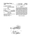
.
US005440339A
States Patent [19]
[11] Patent Number:
Harrison et al.
[45]
Date of Patent:
[54] SYSTEM AND METHOD FOR TESTING
AverKey Pocket Size VGA to Video User’s Manual,
Issue No. 1 Nov. 15, 1992.
[75] Inventors: John R. Harrison; George B.
Primary Examiner-James J. Groody
Stanescu, both of Scarborough,
Assistant Examiner-Nina N. West
Attorney, Agent, or Firm-Jack D. Slobod
Canada
[73] Assignee: U.S. Philips Corporation, New York,
NY.
tested as follows. The video card of a computer is con
Apr. 13, 1994
Int. Cl.6 ........................................... .. H04N 17/02
[58]
Field of Search ............. .. 348/177, 178, 180, 181,
US. Cl. .................................. .. 348/189; 348/177;
348/ 180; 348/181; 348/ 184
348/182, 189, 190, 191, 194, 184, 185; H04N
17/02; 345/155, 132, 148, 149, 147, 153, 904
References Cited
U.S. PATENT DOCUMENTS
3/ 1990 Ohtake et a1. ..................... .. 348/ 181
4,974,080 11/1990 Fritchie et al.
5,343,242
5,345,263
ABSTRACT
trolled to output equal video intensity levels of red,
[51]
[52]
4,910,681
[57]
The intensity output of a monochrome interlaced video
monitor typically used in medical imaging may be
[21] Appl.'No.: 227,212
[56]
Aug. 8, 1995
OTHER PUBLICATIONS
INTENSITY RESPONSE OF A MEDICAL
MONOCHROME VIDEO MONITOR
[22] Filed:
5,440,339
348/ 181
348/ 189
green, and blue for a time sequenced series of different
levels. These video signals are combined and attenuated
such that the peak level of the series is about 700 mV,
which is the industry standard for peak white on a
monochrome monitor. The sync pulses from the video
card are adjusted to about —300 mV, which is the in
dustry standard for sync pulses driving a monochrome
video monitor and are combined with the combined
7 video signal to produce an intensity test signal for driv
ing the monitor. The video card is controlled to pro
duce a high line rate to drive video monitors having an
(approximately double) high line rate and to produce a
low line rate to drive video monitors having (an approx
imately double) low line rate.
9/
8/1994
1994 Rowsell
Miller ................................
et al.
.. 348/ 191
12 Claims, 3 Drawing Sheets
10
....... "1:112.--" ‘6
a:
l4
7 ::1’:: VIDEO2%TEST
/,L\
VIDEO
: “PROCESSOR H CARD
E
: v
2 A
;
l'
-. ........................ n: 19
SIGNAL
GENERATION
lfé‘é‘é’?ili‘éi
<
21
4-‘
__ “6*”
SENSOR
ADAPTER
24
(
US. Patent
Aug. s, 1995
Sheet 1 of 3
52m
“2 18 0
QN
mm
r
V
5:89>Eu:
39>@22a0: 5%\
,
v,
aim?
5,440,339
US. Patent
Aug. s, 1995
5,440,339
Sheet 2 0f 3
@
INPUT Am
LINE RATE
I
SET VIDEO CARD TO
SELECTED LINE RATE
I
SET VIDEO INTENSITY "34
LEVEL, V, TO 0
——+I
GENERATE SYNC PULSES
AND EOUAL LEVELS OF
P\$
RED/GREEN/BLUE AT
CURRENT VIDEO INTENSITY
LEVEL AND DRIVE MONITOR
I
RECORD MONITOR "38
INTENSITY OUTPUT
44
I
COMPARE MONITOR
INTENSITY OUTPUTS
WITH STANDARD
‘ I
INCREMENT V
END
FIG. 2
1
5,440,339
2
produce an interlaced monochrome video monitor test
SYSTEM AND METHOD FOR TESTING
INTENSITY RESPONSE OF A MEDICAL
MONOCHROME VIDEO MONITOR
signal.
In another aspect of this invention, there is provided
a method for testing the intensity output of a medical
interlaced monochrome video monitor, comprising the
steps of: controlling a computer video card, of the type
BACKGROUND OF THE INVENTION
having
red, green, and blue video outputs, horizontal
1. Field of the Invention
and vertical sync outputs and a line rate substantially
This invention relates to a system and method for
half the line rate of said monochrome video monitor, to
producing an intensity test signal for a medical mono 10
output a video signal on one or more of said red, green
chrome video monitor.
and blue video outputs, having a de?ned video intensity
2. Description of the Related Art
level, for a time sequenced series of different levels;
High performance monochrome video monitors are
producing a single grey-scale video signal from the one
typically used in the ?eld of medical diagnostic video
or more of said red, green, and blue video outputs of
imaging. This use requires a high quality video output
said video card on which a video signal has been output;
from the monitor. However, the video quality of a mon
receiving the sync signals of said video card and adjust
itor does degrade with time. Therefore, it is important
ing the voltage level of said sync signals to about nega
for the calibre of the monitor output to be checked
tive 300 mV; mixing said sync signals with said grey
regularly. Medical monitors are typically tested by
scale signal to produce a monochrome video monitor
trained technicians with the aid of devices which cause
intensity test signal and driving a monochrome monitor
the monitors to display test patterns for the technician
with said test signal; sensing the intensity of light emit
to view for defocussing and distortions. Generally the
ted by said monochrome monitor for each signal level
technicians also visually check the intensity of the moni
of said monochrome monitor test signal; and comparing
tor’s output in response to these test patterns. Visual
the sensed intensities with a pre-determined intensity
intensity testing is, however, only an approximate mea 25 response in order to test the intensity response of said
sure of the intensity response of the monitor, not only
because of its subjective element from technician to
technician, but also because of the impact of variable
ambient light conditions. Further, medical mono~
chrome monitors generally operate with one of two line
monochrome monitor.
rates: 525 lines per screen or 1049 lines per screen. This
BRIEF DESCRIPTION OF THE DRAWINGS
FIG. 1 is a schematic view of a system for producing
a test signal for a monochrome video monitor,
FIG. 2 is a ?ow diagram of the software control for
requires different test equipment for monitors with dif
the system of FIG. 1, and
FIG. 3 is a schematic view detailing a portion of FIG.
ferent line rates.
When a medical monitor is in use, an operator who is
not satis?ed with a particular image may adjust the
brightness and contrast controls of the monitor in an
1.
thereby obscuring potentially important image features.
DETAILED DESCRIPTION OF THE
PREFERRED EMBODIMENTS
With reference to FIG. 1, a system 10 for producing
an intensity test signal for a monochrome video monitor
Further, these reset controls will impact on future use of
the monitor and, when such a reset monitor comes up
sor 14 connected for two-way communication with a
attempt to improve the image clarity. However, this
could wash out grey-scale gradations in the image
comprises a portable computer 12, with a microproces
for testing, it is not certain that the technician will prop
erly return the brightness and contrast controls to their
video card 16. The video card is of the type having red,
known prior art.
can be controlled to generate a low line rate of about
240 lines per screen, as well as the normal VGA (high)
line rate of about 480 lines per screen. With a VGA
card, each video colour output line can be set to one of
green, and blue video outputs on lines 18 and horizontal
and vertical sync outputs on lines 19. The video card
optimal settings.
45 may be a VGA card which, as is explained hereinafter,
This invention seeks to overcome drawbacks of the
SUMMARY OF THE INVENTION
According to this invention, there is provided a sys
tem for producing an intensity test signal for a medical
interlaced monochrome video monitor, comprising:
means for controlling a computer video card of the type
sixteen intensity levels which allows the card to gener
ate a variety of colours. The output of the video card is
connected to video test signal generation adapter 20.
The output of the adapter appears on line 21 and inputs
having red, green, and blue video outputs and horizon
tal and vertical sync outputs and generating video and
a monochrome video monitor 22. A light sensor 24 is
sync signals at a line rate substantially half the line rate
of monochrome video monitors for which said system is
designed for use, to output a video signal on one or
more of said red, green and blue video outputs at a
the microprocessor 14.
positioned to receive light from the centre of the moni
tor screen. The output of the light sensor feeds back to
With reference to FIG. 2 in conjunction with FIG. 1,
in overview, the system 10 operates as follows. Com
de?ned video intensity level, for a time sequenced series 60 puter 12 has a resident software utility which can switch
of different video intensity levels; means for connection
a VGA video card between CGA-type line rate of 240
to the one or more of said red, green, and blue video
lines per screen and the normal VGA line rate of 480
outputs of said video card on which said control means
lines per screen. A software utility providing this opera
outputs a video signal for producing a single grey scale
tion is sold by Yuan Technology, Inc. of Taiwan under
video signal; means for receiving the sync signals of said 65 the trade mark DEMOKEY. An operator inputs the
video card and for adjusting the voltage level of said
microprocessor 14 with the line rate of the particular
sync signals to about negative 300 mV; means for mix
video monitor 22 under test (block 30). This video line
ing said sync signals with said grey-scale video signal to
rate may either be a 525 lines per screen (low) rate or a
5,440,339
3
4
1049 lines per screen (high) rate. If the video line rate is
mV. Consequently, the test signal permits an accurate
1049, then the video card is switched to its high line rate
of 480 lines per screen and, conversely, if the video line
rate is 525, the video card is switched to its low line rate
of 240 lines per screen (block 32).
For reasons detailed hereinafter, it has been found
adapted for testing monochrome video monitors used
for medical imaging.
The image formed by a medical imaging system in
variably covers the centre of the video monitor screen
that a 480 line per screen line rate is sufficient to drive
a 1049 lines per screen interlaced video monitor without
use and is the ?rst to degrade. Recognising this, the
the monitor locking up and, similarly, that a 240 lines
per screen rate will drive a 525 lines per screen inter
laced video monitor.
,
After a line rate is input to the computer 12, the mi
croprocessor zeros a video intensity level indicator
(block 34). The processor next controls the video card
to output equal signal levels on the red, green and blue
video signal lines 18, at the current video intensity level
(block 36). Throughout, the video card will generate
test for a monochrome video monitor and is therefore
such that the centre of the screen sustains the heaviest
video content of the test signal is arranged to illuminate
only the centre of the monitor screen; the light sensor
24 (FIG. 1) is positioned to receive only the output from
the centre of the screen. Outside the screen centre, the
video intensity level is set to black (zero level).
The reason the video card line rates of 240 or 480
lines per screen drive a video monitor having 525 or
1049 lines per screen, respectively, is due to the follow
ing. Monochrome video monitors utilise interlaced
scanning. Consequently, with a normal video signal, for
sync pulses on lines 19 at the line rate (high or low)
which has been chosen for the card.
each frame of the picture, two ?elds are scanned by the
The colour signal output lines are combined in 20 monitor. All odd lines of the frame are ?rst traced on
adapter 20. Further, in adapter 20, the sync pulses on
the screen and then all even lines are traced. Therefore,
lines 19 are adjusted to the level of about —-300 mV,
on any one scan, only one-half of the screen lines are
which is the standard for sync pulses driving a video
scanned. Because the line rate produced by the video
monitor. The adjusted sync pulses are then mixed with
card is substantially one-half of the line rate of the video
the mixed video signal to generate a monochrome video 25 monitor, one frame of the picture generated by the
monitor test signal on line 21 which drives monitor 22
video card is produced in each ?eld scanned. Thus
(block 36).
one-half of the screen lines are not used in producing a
The light sensor 24 picks up the intensity output from
frame.
the monitor 22 and feeds this back to the processor 14.
Even with interlaced operation, the video card does
The processor records this feedback signal (block 38). 30 not produce quite as many lines per frame as are
The video intensity level of zero is set to correspond to
a very small output for a black level video signal, rather
scanned per ?eld. However, this does not affect the.
operation of this invention because the unscanned lines
than a zero output, so that a non-zero reference signal
are at the periphery of the monitor screen.
will be expected from the light meter.
While a monitor responding to an analog video signal
Next the video intensity level indicator is incre 35 will have an in?nite number of grey-scale levels, it has
mented (block 42) and the video card is controlled to
been found that measuring intensity response with a
output equal signal levels on the red, green and blue
sixteen level grey-scale is a satifactory determiner of the
signal lines 18 at the new (larger) video intensity level
performance of a video monitor utilised for medical
(block 36). The new output intensity signal is then re
imaging.
corded. This cycle is repeated until all sixteen grey 40 FIG. 3 details the implementation of the video test >
scale steps have been recorded.
signal generation adapter 20. Turning to FIG. 3, adapter
In this way, the video monitor intensity test signal
20 has three inputs 118, one for connection to each of
generates a time sequenced grey-scale on monitor 22,
the video output lines of a video card. Lines 52a, 52b,
beginning with black and progressing through ever
52c extend from the inputs 118 to video mixer 50. The
lighter greys. Adapter 20 adjusts the level of the com 45 video mixer incorporates a resistor 54a, 54b, 540 in lines
bined video signal so that the last (sixteenth) level pro
52a, 52b, 52c, respectively. The lines 52a, 52b, 52c are
duced by the video card results in an approximately 700
combined at node 56. Line 58 from the node terminates
mV video signal, which is the industry standard for
in potentiometer 62 of video level regulator 60. Line 64
peak white for a monochrome video monitor.
from the potentiometer extends through node 66 of
The intensity output by the monochrome monitor is
sync mixer 70 to the capacitor 68 of the sync mixer.
recorded by the microprocessor for each level in the
Output line 21 extends from node 66 of the sync mixer
grey-scale. After the video intensity level has stepped
70 to RCA plug 122. This plug is designed for connec
through sixteen‘ gradations, the test is complete. The
tion to a seventy-?ve ohm monochrome video monitor.
processor then compares the recorded intensity output
The adapter 20 also has two inputs 119 for connection
levels of the monitor with a standard stored in the pro 55 to the horizontal and vertical sync outputs of a video
card. Line 72a is intended to be input with the horizon
monitor is functioning within pre-determined limits
tal sync pulses of the video card and line 72b with the
(block 44). If the monitor fails to produce satisfactory
vertical sync pulses of the card. Both lines enter sync
results and adjustment of brightness and contrast con
level adjuster 80 wherein they are combined and the
trols do not solve the problem, it is indicative that the
sync pulses attenuated with appropriate resistors. The
cessor in order to derive an indication of whether the
monitor has degraded to the point where it should be
replaced.
output lines 82 and 84 from the sync level adjuster carry
both horizontal and vertical attenuated sync pulses.
A given computer will generate highly consistent
Line 82 is connected to terminal 92 of line rate switch 90
video card voltage output levels. Because of this, the
and line 84 is connected through inverting ampli?er 100
test signal produced by the system of this invention can 65 to a terminal 94 of line rate switch 90. The line rate
consistently produce close to the video standard nega
switch 90 has a coil 96 which is connected between
tive 300 mV for sync pulses and a grey-scale with a peak
branch 74 of line 72a and ground. A shuttle 97 is free to
white voltage value of about the video standard 700
move between switch terminals 92 and 94. A wiper 98
5
5,440,339
connects the shuttle to line 99 which extends to potenti
ometer 112 of sync level regulator 110. Line 114 extends
6
signal on its three colour lines and then a horizontal
sync pulse. Consequently, the output on line 21 will
comprise, repetitively, a horizontal sync pulse and then
between the other side of the potentiometer and capaci
tor 68 of sync mixer 70.
a video signal on a single line, which is the format for a
A branch 76 from line 720 extends to diode 122 of 5 video signal. After outputing 480 horizontal sync
power supply 120 and a branch 78 from line 72b extends
pulses for the high line VGA rate (or 240 pulses when
to diode 124 of the power supply. The output from the
diodes merge into line 126 which has a capacitor 128
extending between the line and ground. Line 126 ex
tends to the power input of the inverting ampli?er 100.
The operation of the adapter 20 of FIG. 3 after con
nection to a computer 12 (FIG. 1) is as follows. Red,
green and blue video signals received from the video
card of the computer at inputs 118 are attenuated by
resistors 54a, 54b, and 54c and combined at node 56 of
video mixer 50. The combined signal is further attenu~
run in low line rate), a vertical sync pulse is generated
which returns the electron beam for the monochrome
video monitor back to its starting position.
The light sensor 24 (FIG. 1) is surrounded by a blind
to shield out ambient light.
As will be appreciated by those skilled in the art, the
system of this invention could be adapted to generate a
monochrome video monitor intensity test signal utilis
ing certain other types of video cards, such as a super
VGA card. Further, the system of this invention could
utilise only one or two of the three colour output lines
from the video card and still have suf?cient power
ated by potentiometer 62 of the video level regulator 60.
The setting of the potentiometer 62 is dependent on the
computer make with which the adapter is used. Differ
levels to produce a multi-level grey scale on a mono
ent computers makes have differing, but known and 20 chrome video monitor.
relatively predictable, video output voltage levels. Po
Rather than feeding back each output signal of light
tentiometer 62 is switchable (manually or through soft
ware) to discrete settings which match the particular
meter 24 (FIG. 1) to the microprocessor, an operator
could record each output. The operator could then
computer to which the adapter is connected so that the
compare the compiled outputs with a standard in order
voltage level of the grey scale video output of the 25 to determine the performance of the monitor. With this
adapter is standardized such that the peak white value
modi?cation, the operator would prompt the micro
of the scale is about 700 mV. The switchable settings
processor when to step through each increment of the
may be determined in the lab for a particular computer
grey-scale.
type.
Other modi?cations will be apparent to those skilled
The standardized grey-scale signal appears on line 64.
in the art and, therefore, the invention is de?ned in the
Recall from FIG. 2 that the grey-scale level is incre
claims.
mented during monitor testing.
What is claimed is:
The horizontal and vertical sync pulses from the
1. A system for producing an intensity test signal for
computer are received by lines 72a, 72b. As will be
a medical interlaced monochrome video monitor, com
appreciated by those skilled in the art, these VGA video
prising:
card generated pulses are on the order of ?ve volts in
- means for controlling a computer video card of the
magnitude. These pulses are therefore attenuated in the
sync level adjuster 80 and the attenuated signals are
placed on both lines 82 and 84.
The horizontal sync pulses are coupled to coil 96 of 40
switch 90 via line 74. If these pulses are negative going
VGA pulses, then these pulses draw shuttle 97 into
contact with terminal 92. If these pulses are positive
going CGA-type pulses, they draw the shuttle into
contact with terminal 94.
45
type having red, green, and blue video outputs and
horizontal and vertical sync outputs and generating
video and sync signals at a line rate substantially
half the line rate of monochrome video monitors
for which said system is designed for use, to output
a video signal on one or more of said red, green and
blue video outputs at a de?ned video intensity
level, for a time sequenced series of different video
intensity levels;
If the pulses are negative going VGA pulses, then
- means for connection to the one or more of said red,
these pulses, in their attenuated form on line 82, are
coupled through switch 90 to line 99. If the pulses are
green, and blue video outputs of said video card on
which said control means outputs a video signal for
positive going CGA-type pulses, then these pulses, in
producing a single grey-scale video signal;
their attenuated form on line 84, are coupled through
inverting ampli?er and switch 90 to line 99. The invert
ing ampli?er converts the CGA-type pulses to negative
going pulses and matches their level to the attenuated
VGA pulses. The power for the inverting ampli?er is
provided by power supply 120 which taps lines 72a, 72b
through diodes 122, 124. The power supply is smoothed
by capacitor 128.
Like potentiometer 62, potentiometer 112 of the sync
- means for receiving the sync signals of said video
card and for adjusting the voltage level of said sync
signals to about negative 300 mV;
- means for mixing said sync signals with said grey
scale video signal to produce an interlaced mono
chrome video monitor test signal.
2. The system of claim I wherein said video card is of
the type which may-generate a low line rate or a high
line rate, said low line rate being substantially half the
level regulator is switchable to discrete settings based
low line rate of a ?rst type of monitor with which said
upon the particular make of computer connected to the 60 system is designed for use and said high line rate being
adapter. This ensures that the negative going sync
substantially half the high line rate of a second type of
pulses on line 99 have a magnitude of about —300 mV
monitor with which said system is designed for use, and
on line 114. These sync pulses on line 114 are mixed
wherein said system includes means to selectively con
with the video signal on line 64 (through capacitor 68)
55
trol said video card to produce a low line rate or a high
at node 66, and the mixed output signal appears on line 65 line rate.
21.
3. The system of claim 1 wherein said video card is of
It will be appreciated by those skilled in the art that a
the type which may be controlled to produce a high line
computer VGA video card alternately outputs a video
rate having negative sync pulses or a low line rate hav
5,440,339 '
7
ing positive sync pulses, said low line rate being sub
8
- producing a single grey-scale video signal from the
stantially half the low line rate of a ?rst type of monitor
with which said system is designed for use and said high
line rate being substantially half the high line rate of a
second type of monitor with which said system is de
signed for use, said system including means to control
said video card to selectively produce high line rate or
low line rate signals; and wherein said means to adjust
the voltage of said sync pulses to about negative 300
one or more of said red, green, and blue video
outputs of said video card on which a video signal
has been output;
- receiving the sync signals of said video card and
adjusting the voltage level of said sync signals to
about negative 300 mV;
- mixing said sync signals with said grey-scale signal
to produce a monochrome video monitor intensity
test signal and driving a monochrome monitor with
said test signal;
- sensing the intensity of light emitted by said mono
chrome monitor for each signal level of said mono
chrome monitor test signal; and
comparing the sensed intensities with a pre-deter
mined intensity response in order to test the inten
sity response of said monochrome monitor.
10. The method of claim 9 wherein said step of con
mV includes means to invert said low line rate sync
signals.
4. The system of claim 1 wherein said video card is of
the type which may be controlled to produce VGA
signals or CGA-type signals, the line rate of said CGA
type signals being about 240 lines per screen, said CGA
type signals being for control of a 525 lines per scrren
monitor with which said system is designed for use and
the line rate of said VGA signals being about 480 lines
per screen, said VGA signals being for control of a 1049
trolling a computer video card comprises controlling
lines per screen monitor with which said system is de 20 the card such that said monochrome monitor test signal
signed for use, said system including means to control
drives said monitor to illuminate the central area of said
said video card to selectively produce VGA signals or
monitor and wherein said step of sensing the intensity of
CGA-type signals; and wherein said means to adjust the
light emitted by said monitor comprises sensing emis
voltage of said sync pulses to about negative 300 mV
sions with alight sensor at the centre of said monitor.
includes means to invert said CGA-type signals.
25
11. A method for producing a medical monochrome
5. The system of claim 1 including light sensing
interlaced video monitor test signal, comprising the
means for sensing the intensity of light output by a
steps of:
monochrome video monitor input with said intensity
test signal.
- controlling a computer video card, of the type hav
ing red, green, and blue video outputs, horizontal
6. The system of claim 5 including means to compare 30
the intensity output of a monochrome video monitor
input with said intensity test signal with a standard and
for indicating whether said monitor meets or does not
meet said standard.
7. The system of claim 2 including light sensing
means for sensing the intensity of light output by a
monochrome video monitor input with said intensity
test signal.
35
monochrome video monitor, to simultaneously
output equal levels of red, green and blue video
signals for a time sequenced series of different lev
els at a selected line rate;
- mixing said video output signals to produce a grey
scale signal;
8. The system of claim 7 wherein means to compare
the intensity output of a monochrome video monitor 40
input with said intensity test signal with a standard and
for indicating whether said monitor meets or does not
meet said standard.
9. A method for testing the intensity output of a medi
cal interlaced monochrome video monitor, comprising
and vertical sync outputs, a ?rst line rate substan
tially half the line rate of a ?rst type of mono
chrome video monitor, and a second line rate sub
stantially half the line rate of a second type of
45
- receiving the sync signals of said video card at said
selected line rate and adjusting the voltage level of
said sync signals to about negative 300 mV; and
- mixing said sync signals with said grey-scale signal
to produce a monochrome video monitor test sig
nal and driving a monochrome monitor with said
tially half the line rate of said monochrome video 50
test signal.
12. The method of claim 11 including the steps of:
- sensing the intensity of light emitted by said mono
chrome monitor for each signal level of said mono
chrome monitor test signal; and
monitor, to output a video signal on one or more of
- comparing each said sensed intensity with a pre
the steps of:
'
- controlling a computer video card, of the type hav
ing red, green, and blue video outputs, horizontal
and vertical sync outputs and a line rate substan
said red, green and blue video outputs, having a
de?ned video intensity level, for a time sequenced
series of different levels;
determined intensity response in order to test the
response of said monochrome monitor.
*
55
65
*
*
*
*