1
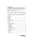
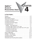
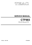
STEPPING SYSTEMS
Sure Step™ Microstepping Drive Specifications
STP-DRV-6575
Input Power
24–65 VDC
(external power supply required; fuse at 7A fast-acting)
Output Current
1.0–7.5 A/phase (peak of sine)
Current Controller
Dual H-bridge digital MOSFET,
4-quadrant PWM at 20 kHz
Input
Signals
5–24 VDC nominal (range: 4–30 VDC); optically isolated,
differential. Minimum pulse width = 250ns. Maximum
pulse frequency = 150 kHz or 2MHz (user selectable).
Function = Step or Step CW pulse.
Direction
5–24 VDC nominal (range: 4–30 VDC); optically isolated,
differential. Minimum pulse width = 250ns. Maximum
pulse frequency = 150 kHz or 2MHz (user selectable).
Function = Direction or Step CCW pulse.
Enable
5–24 VDC nominal (range: 4–30 VDC); optically isolated,
differential.
Function = disable motor when closed.
Fault
30 VDC / 80mA max, optically isolated photodarlington,
sinking or sourcing.
Function = closes on drive fault.
Rotary Switch Selectable Select motor based on part number, or by motor current.
Function
WARNING
Sheet 1 of 2
DIMENSIONS
0.13
[3.2]
Step and Direction:
4X Ø0.14
[Ø3.6]
Step signal = step/pulse; Direction signal = direction.
Step Pulse
Jumper
Type
Step CW & CCW:
Selectable
Step signal = CW step; Direction signal = CCW step.
Functions
Step Pulse Select 150 kHz or 2MHz
Noise Filter
Current
Reduction
4.66
[118.4]
4.40
[111.8]
Dimensions = in [mm]
2.98
[75.6]
Reduce power consumption and heat generation by
limiting motor running current to 100%, 90%, or 80%
of maximum. Current should be increased to 120% if
microstepping.
(Torque is reduced/increased by the same %.)
0.89
[22.7]
1.04
[26.5]
Reduce power consumption and heat generation by
4.42
[112.3]
2 X R0.09
[R2.2]
0.41
[10.5]
0.22
[5.6]
Idle Current limiting motor idle current to 90% or 50% of running
Reduction
current. (Holding torque is reduced by the same %.)
DIP Switch
Anti-resonance and damping feature improve motor
Selectable
Functions Load Inertia performance. Set motor and load inertia range to 0–4x
0.35 1.30
[8.9] [33.0]
or 5–10x.
For smoother motion and more precise speed, set the
pulse step resolution to 20000, 12800, 5000, 2000, 400
smooth, 400, 200 smooth, or 200 steps/rev.
Self Test
Automatically rotate the motor back and forth two turns
in each direction in order to confirm that the motor is
operational.
Drive Cooling Method
Natural convection (mount drive to metal surface)
Mounting
Use (2) #6 screws to mount wide or narrow side to metal
surface
Removable Connectors
Motor & Power Supply:
screw terminal blocks Phoenix Contact 1757051
Signals:
screw terminal blocks Phoenix Contact 1803633
Weight
10.8 oz [306g] – (including mating connectors)
Operating Temperature
0–85 °C [32–185 °F] – (interior of electronics section)
Ambient Temperature
0–50 °C [32–122 °F]
– (drive must be mounted to suitable heat sink)
Humidity
maximum 90% non-condensing
Agency Approvals
CE (EMC & LVD); RoHS
For a complete user manual, please visit www.automationdirect.com
BLOCK DIAGRAM
24-65 VDC
from external power supply
3.3/5/15V
Regulators
Voltage
Sensors
Status LEDs
STEP
DIR
Optical
Isolation
Digital
Filter
EN
Optical
Isolation
Software
Filter
OUT1
Optical
Isolation
Motor Selection
789
AMPLIFIER
Overcurrent
Sensors
DSP
12345678
Step
Resolution
CD
AB E
Data Sheet: STP-DRV3_DS, 1st Ed, Rev C – 12/02/2014
• Never mount the drive in a space where there is no air flow, or
where other devices can heat the surrounding air to 50°C [122°F].
• Never put the drive where it can get wet, or where metal or other
electrically-conductive particles can get on the circuitry.
• Always provide air flow around the drive. Minimum allowable
spacing between multiple drives is 0.5 in [13 mm].
456
To minimize the risk of potential safety problems, you should
follow all applicable local and national codes that regulate the
installation and operation of your equipment. These codes vary
from area to area. It is your responsibility to determine which
codes should be followed, and to verify that the equipment, installation, and operation are in compliance with the latest revision of
these codes.
Equipment damage or serious injury to personnel can result from
the failure to follow all applicable codes and standards. We do
not guarantee the products described in this publication are suitable for your particular application, nor do we assume any
responsibility for your product design, installation, or operation.
If you have any questions concerning the installation or operation
of this equipment, or if you need additional information, please
call our technical support at 770-844-4200.
This publication is based on information that was available at the
time it was printed. At Automationdirect.com® we constantly
strive to improve our products and services, so we reserve the
right to make changes to the products and/or publications at any
time without notice and without obligation. This publication may
also discuss features that may not be available in certain revisions of the product.
The STP-DRV-6575 drive can be mounted on the wide or the
narrow side of the chassis using (2) #6 screws. Fasten the drive
securely to a smooth, flat, metal surface that will help conduct
heat away from the chassis. Otherwise, forced air flow from a fan
may be required to prevent overheating. WARNING:
23
Note: STP-DRV-6575 Drives are suitable for driving 2-phase and 4-phase
stepping motors with 4, 6, or 8 leads.
Output
Signal
Step
MOUNTING THE DRIVE
F0 1
STP-DRV-6575 MICROSTEPPING DRIVE
Part Number
Current
Idle Current
Steps/Rev
Load Inertia
Self Test
motor
VDC –
Connecting STP-DRV-6575 Drive to Indexer with Sinking Outputs
A+
A–
B+
STP-PWR-xxxx
B–
STPDRV-xxxx
Extension Cable 12" Motor Pigtail
with Connector
with Connector
STP-EXT(H)-020
DIR+
DIR
DIR–
Indexer
with
Sinking
Outputs
Step Motor
STP-MTR(H)-xxxxx(D)
STEP
STP-DRV-6575
Drive
STEP+
EN+
STEP–
EN–
N/C
N/C
Connecting STP-DRV-6575 Drive to Indexer with Differential Outputs
Indexer with
Differential
Outputs
(5–24 VDC)
CONNECTING THE POWER SUPPLY
• Connect the green ground screw to earth ground
• Use 18 or 20 AWG wire.
Fuse* EMI**
DIR+
DIR+
DIR–
DIR–
STP-DRV-6575
Drive
STEP+
STEP+
EN+
STEP–
STEP–
EN–
V+
N/C
N/C
CONNECTING THE INPUT SIGNALS – ENABLE
V–
Step
+
Motor
VDC
Power
Supply
–
(5–24 VDC) +V OUT
Stepper Drive
Connecting STP-DRV-6575 Drive EN to Switch or Relay
* External fuse not req'd when
using an STP-PWR-xxxx P/S; fuse is internal.
** CE use requires an EMI line filter.
+
5-24 VDC
Power
Supply
STP-PWR-48xx or STP-PWR-3204 power supplies from
AutomationDirect are good choices to power the step-motor drive.
If the power supply you choose does not have a fuse on the
output, you will need to install a fast-acting 7A fuse on the “+”
power supply lead.
WARNING: Do not to reverse the polarity from the power supply
to the drive. Reverse connection will destroy your drive and void
the warranty.
STP-DRV-6575
Drive
+
+
5-24 VDC
Power
Supply
-
NPN
Proximity
Sensor
+
5-24 VDC
Power
Supply
-
-
output
PNP
Proximity
Sensor
EN–
Note: STEP and DIR inputs can be converted to STEP CW and STEP CCW by
moving the internal jumper S3.
Sheet 2 of 2
ON 5 6 7
20000
STP-DRV-6575
Drive
relay coil
(inductive load)
1N4935
suppression
diode
FAULT+
FAULT–
Load
+
5-24 VDC
Power
Supply
-
3.03
1.60
434
51
2.04
2.0
83
0.37
2.65
1.40
586
82
2.40
2.0
125
0.56
3.30
2.00
883
37
2.40
2.8
166
1.46
2.36
0.08
1172
271
3.36
2.8
276
2.60
3.82
1.10
1949
475
3.36
2.8
434
7.66
7.70
1.11
3065 1402
3.36
5.6
287
2.60
1.18
0.40
2025
371
6.72
6.3
428
7.66
1.52
0.25
3021 1402
7.56
6.3
803
14.80 2.07
0.03
5668 2708
7.56
6.3
1292 21.90 4.14
0.49
9123 4008
7.56
Self Test
Idle Current
Reduction
4
ON 4
50% 90%
ON
8
8
ON OFF
5 6 7
5 6 7
5 6 7
5 6 7
5 6 7
5 6 7
5 6 7
12800
5000
2000
400
SMOOTH
400
200
SMOOTH
200
• Jumper in “1-2” position – Step & Direction (factory default)
• Jumper in “1-3” position – Step CW / Step CCW
Jumper S4 – Step Pulse Noise Filter
• Jumper in “1-2” position – 2MHz
• Jumper in “1-3” position – 150 kHz (factory default)
+
5-24 VDC
Power
Supply
-
+
FAULT+
5-24 VDC
Power
Supply
STP-DRV6575 Drive
FAULT–
Load Inertia
Jumpers S3 and S4 are located on the internal circuit board.
They can be accessed by removing the drive’s front cover.
Jumper S3 – Step Pulse Type
Connecting Fault Output as Sinking Output Connecting Fault Output as Sourcing Output
STP-DRV6575 Drive
0.28
JUMPER SETTINGS
EN–
Connecting STP-DRV-6575 Fault Output to Inductive Relay
FAULT–
61
EN+
FAULT+
• STEP: a high speed digital input for step pulse commands;
5–24 VDC logic
• DIR: a high speed digital input for the direction signal;
5–24 VDC logic
• EN: a 5-24V input for commanding the removal of power from the
motor; also clears faults and re-enables the motor in the case of
drive faults, e.g. over-current/short-circuit faults
custom NEMA 34
1.7
0–2
3
4
5
6
7
8
9
A
B
C
D
E
F
Step Resolution (steps/rev)
Do not connect more than 30 VDC. Current must not exceed 80 mA.
STP-DRV6575 Drive
custom NEMA 23
4.0
STP-DRV-6575
Drive
CONNECTING THE FAULT OUTPUT SIGNAL
The STP-DRV-6575 drive has three inputs:
4.0
1 2
1 2
1 2
ON 1 2
3
ON 3
100% 90%
80% 120%
5-10x 0-4x
(Use 120% when microstepping)
Connecting STP-DRV-6575 Drive EN to PNP
+
custom NEMA 17
Current Reduction
EN+
output
reserved
1.3
DIP SWITCH SETTINGS (FACTORY DEFAULT = ALL SWITCHES OFF)
EN–
Connecting STP-DRV-6575 Drive EN to NPN
CONNECTING THE INPUT SIGNALS
Data Sheet: STP-DRV3_DS, 1st Ed, Rev C – 12/02/2014
switch or relay
(closed = logic low)
-
CONNECTING THE MOTOR
WARNING: When connecting a step motor to the STP-DRV-6575
drive, be sure that the motor power supply is switched off. When
using a motor not supplied by AutomationDirect, secure any
unused motor leads so that they can’t short out. Never disconnect the motor while the drive is powered up. Never connect the
motor leads to ground or directly to the power supply. (See
Typical Wiring Diagram on the back side of this data sheet for the
step motor lead color code of AutomationDirect-supplied motors.
EN+
n/a
n/a
n/a
n/a
-17040
-17048
-17060
-23055
-23079
-34066
H-23079
H-34066
H-34097
H-34127
Drive Configuration Data
Rotary Switch
Position
N/C
Current
(peak sine A)
N/C
Inertia
(g·cm2)
EN–
Torque
(mN·m)
STEP+
STP-DRV-6575 Motor Selection Table
Motor Data
Resistance
(Ω)
EN+
Inductance
(mH)
STEP–
Roter Inertia
(oz·in2)
STEP
ROTARY SWITCH SETTINGS – MOTOR SELECTION
STP-DRV-6575
Drive
Holding
Torque (oz·in)
DIR+
Current
(A/phase)
+
DIR–
DIR
Motor
STP-MTR
-xxxxx
Logic Motor
Power Power
5VDC xx VDC
VDC +
COM
F0 1
SureStep Typical
Wiring Diagram
–
Cable Color Code
Term Wire Pin #
A+
Red
1
A– White
2
B+ Green 3
B– Black
4
Indexer with
Sourcing
Outputs
(5–24 VDC)
789
23
Connecting STP-DRV-6575 Drive to Indexer with Sourcing Outputs
TYPICAL WIRING DIAGRAM
Step Motor
Power Supply
456
CONNECTING THE INPUT SIGNALS – STEP & DIRECTION
CD
AB E
STP-DRV-6575
Microstepping Drive
STEPPING SYSTEMS
Load
-
For a complete user manual, please visit www.automationdirect.com
Remove connectors and cover to access Jumpers
S3 and S4. They are located on the upper
left corner of the circuit board.
Jumper S4:
Step Pulse Noise Filter
Jumper S3:
Step Pulse Type