1
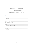
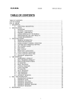
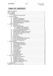
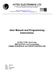
7HFKQLFDO
,QIRUPDWLRQ
0DQXDO
9HUVLRQ
9 July 1999
02'9%
C-RAMS
SEQUENCER
09/07/99
V551B User's Manual
Version 1.1
TABLE OF CONTENTS
TABLE OF CONTENTS ...............................................................................................................i
LIST OF FIGURES.......................................................................................................................ii
LIST OF TABLES.........................................................................................................................ii
1. DESCRIPTION ......................................................................................................................1
1.1. FUNCTIONAL DESCRIPTION..............................................................................1
2. SPECIFICATIONS.................................................................................................................3
2.1. INPUTS .................................................................................................................3
2.2. OUTPUTS .............................................................................................................3
2.3. OTHER COMPONENTS .......................................................................................4
2.4. POWER REQUIREMENTS...................................................................................4
3. VME INTERFACE..................................................................................................................7
3.1. ADDRESSING CAPABILITY.................................................................................7
3.2. DATA TRANSFER CAPABILITY...........................................................................7
3.3. MODULE IDENTIFIER WORDS ...........................................................................8
3.4. INTERRUPT VECTOR REGISTER ......................................................................9
3.5. INTERRUPT LEVEL REGISTER ..........................................................................9
3.6. CLEAR REGISTER ...............................................................................................9
3.7. TRIGGER REGISTER...........................................................................................9
3.8. STATUS REGISTER.............................................................................................10
3.9. TEST REGISTER..................................................................................................11
3.10. NUMBER OF CHANNELS REGISTER.................................................................11
3.11. T1 REGISTER.......................................................................................................12
3.12. T2 REGISTER.......................................................................................................12
3.13. T3 REGISTER.......................................................................................................12
3.14. T4 REGISTER.......................................................................................................13
3.15. T5 REGISTER.......................................................................................................13
3.16. WRITE INTERNAL DAC .......................................................................................13
4. OPERATING MODES ...........................................................................................................14
4.1. GENERAL INFORMATION ...................................................................................14
4.2. CONNECTION SCHEMES ...................................................................................16
4.2.1. USING MOD. V550 AND V551B WITH JAUX DATAWAY ...................16
4.2.2. USING MOD. V550 AND V551B WITHOUT JAUX DATAWAY............18
4.3. POWER-ON CONFIGURATION...........................................................................20
4.4. STANDARD OPERATIONS ..................................................................................20
4.5. TEST OPERATIONS.............................................................................................22
4.6. INTERRUPT GENERATION .................................................................................23
5. REFERENCES ......................................................................................................................24
APPENDIX A: ELECTRICAL DIAGRAMS ...................................................................................A.1
i
09/07/99
V551B User's Manual
Version 1.1
LIST OF FIGURES
Fig. 1.1: Block Diagram................................................................................................................2
Fig. 2.1: Front Panel.....................................................................................................................5
Fig. 2.2: Components Locations ..................................................................................................6
Fig. 3.1: Module Identifier Words .................................................................................................8
Fig. 3.2: Interrupt Vector Register ................................................................................................9
Fig. 3.3: Interrupt Level Register..................................................................................................9
Fig. 3.4: Status Register...............................................................................................................10
Fig. 3.5: Test Register..................................................................................................................11
Fig. 3.6: Number of Channels Register........................................................................................11
Fig. 3.7: T1 Register.....................................................................................................................12
Fig. 3.8: T2 Register.....................................................................................................................12
Fig. 3.9: T3 Register.....................................................................................................................12
Fig. 3.10: T4 Register...................................................................................................................13
Fig. 3.11: T5 Register...................................................................................................................13
Fig. 3.12: Internal DAC.................................................................................................................13
Fig. 4.1: System Layout with connections via Auxiliary VME bus ................................................17
Fig. 4.2: System Layout with Connections without Auxiliary VME bus ........................................19
Fig. 4.3: Standard Operation Sequence.......................................................................................21
Fig. 4.4: Test Operation Sequence ..............................................................................................22
LIST OF TABLES
Table 3.1: Address Map ...............................................................................................................8
ii
09/07/99
V551B User's Manual
Version 1.1
1. DESCRIPTION
1.1. FUNCTIONAL DESCRIPTION
The Model V551B CAEN C-RAMS Sequencer is a 1-unit wide VME module that handles
the Data Acquisition from multiplexing front-end chips. The module is well suited to
handle the VA family of chips (produced by IDE AS, Oslo) but due to its flexibility it can
also be used with similar chips (Amplex, Gasplex, etc.).
The V551B has been developed to control the signals from/to the C-RAMS (CAEN
Readout for Analog Multiplexed Signals) boards Mod. V550, the latter taking care of the
conversion of the multiplexed signals from the front end boards housing the above chips.
A single V551B can control up to 19 C-RAMS modules in a complete VME crate, thus
enabling the readout of 19*(2*2016) = 76608 multiplexed detector channels. The Mod.
V551B is controlled via VME bus. The number N of detector channels to be read out by
the C-RAMS can be programmed via VME up to 2047 (though the V550 C-RAMS can
accept up to 2016 detector channels).
The multiplexing frequency can be set via VME from 100 kHz to 5 MHz, with
programmable Duty Cycle. The delay between the multiplexing Clock signal and the
Convert signal of the acquisition cards can be adjusted to wait for the settlement of the
analog signal coming from the multiplexers. The delay between the Trigger and the Hold
signal and the delay between the Hold and the Conversion Cycles are also
programmable, thus extending the Module's flexibility.
The module houses a VME RORA INTERRUPTER[1]: via VME it is possible to program
the interrupt generation on the condition that the DRDY signal is asserted, signaling that
at least one channel in a system has data to be read out.
The V551B Model uses the P1 and P2 connectors of VME and, optionally, the auxiliary
connector for the CERN V430 VMEbus crate (Jaux Dataway)[1, 2] in order to handle, if
desired, the CONV, DRDY and CLOUT signals via the Jaux connector.
The module works in A24/A32 mode. The data transfer occurs in D16 mode.
Page 1 of 24
09/07/99
V551B User's Manual
Version 1.1
IDENTIFIER
TRIG
NCH, T1..T5
CONV
BUSY
VME
INTERFACE
MAIN SEQUENCER
CLIN
IRQ
CLOUT
INTERRUPTER
INT. LEVEL
CONTROL
STATUS /ID
DRDY
Fig. 1.1: Block Diagram
Page 2 of 24
09/07/99
V551B User's Manual
Version 1.1
2. SPECIFICATIONS
2.1. INPUTS
- DATA READY:
Std. TTL. level, 50 Ω impedance (also on Jaux), active high,
on a LEMO 00 type connector.
A green LED lights up when a DRDY signal is asserted.
- TRIG(1):
Std. NIM level, high impedance, on two LEMO 00 type
bridged connectors (for daisy chaining); requires termination
if not chained, see note (1) here below.
min. width: 50 ns, must be active high.
A green LED lights up when a TRIG signal is asserted.
- CLEAR IN(1):
Std. NIM level, high impedance, on two LEMO 00 type
bridged connectors (for daisy chaining); requires termination
if not chained, see note (1) here below.
Min. width 50 ns.
(1) This is a high impedance input and is provided with two bridged connectors for daisy chaining.
Note that the high impedance makes this input sensitive to noise, so the chain has to be terminated
on 50 Ω on the last module; the same is needed also if one module only is used, whose input has thus
to be properly matched.
2.2. OUTPUTS
- BUSY:
Std. TTL positive open collector on 50 Ω impedance, active high.
Two LEMO 00 type bridged connectors (for daisy chaining).
A red LED lights up when a BUSY signal is asserted.
- CONTROL:
Header 3M type, 10+10 pins, carrying the following signals:
VCAL: Analog Voltage, 0 to 5 V, 50 mA max. current, Positive or
Negative polarity (selection via DIP switch SW1).
TEST PULSE: TTL differential level, 110 Ω impedance, Active
high.
TEST ON: TTL differential level, 110 Ω impedance, Active high.
DELAY ON: TTL differential level, 110 Ω impedance, Active high.
SHIFT IN: TTL differential level, 110 Ω impedance, Active low.
An SH-IN test point allows to monitor the SHIFT-IN signal.
CLOCK: TTL differential level, 110 Ω impedance, Active low.
A CLOCK test point allows to monitor the CLOCK signal.
HOLD: TTL differential level, 110 Ω impedance, Active low.
A HOLD test point allows to monitor the HOLD signal.
DRESET: TTL differential level, 110 Ω impedance, Active high.
ARESET: TTL differential level, 110 Ω impedance, Active low.
N.B.: The CLOCK, CONV, HOLD and SH-IN signals on test points are std. TTL level, all
active high (disregarding their active level on the Control Bus and front panel
connectors).
Page 3 of 24
09/07/99
V551B User's Manual
Version 1.1
- CONVERT:
Std. NIM level on 50 Ω impedance;
two LEMO 00 type connectors (fan-out of 2).
differential ECL on Jaux connector, active high.
A CONV test point allows to monitor the CONVERT signal.
A green LED lights up during a convert cycle.
- CLEAR OUT:
Std. NIM level on 50 Ω impedance;
two LEMO 00 type connectors (fan-out of 2).
differential ECL on Jaux connector.
2.3. OTHER COMPONENTS
(refer to Fig. 2.1, 2.2)
DISPLAYS
- 1, "DTACK", green LED, VME Selected. It lights up during a VME access or an Interrupt
Acknowledge cycle.
INTERNAL SWITCHES
- 1 DIP switch "SW1"; to perform the polarity selection of the VCAL voltage (positive,
negative).
- 1 DIP switch "SW2 (ARESET)"; to enable/disable the analog reset to the front end chips
(ON=Enabled).
- 2 DIP switches "SW3 (CONV)"; to enable/disable the CONV generation via the Jaux
backplane lines CK and CK* (ON=Enabled).
- 1 DIP switch "SW4 (DRDY)"; to enable/disable the DRDY detection on the Jaux
backplane line SG (ON=Enabled).
- 2 DIP switches "SW5 (CLEAR)"; to enable/disable the CLEAR generation via the Jaux
backplane lines CL and CL* (ON=Enabled).
- 1 DIP switch "SW6 (VEE/AUX)"; for the -5 V power selection: via this switch it is
possible to choose the -5 V power supply coming from the -12 V VME power supply (V EE
position) or directly from the -5 V Jaux power supply (AUX position).
- 4 rotary switches for the module's VME Base Address selection.
N.B.: By setting the three DIP switches SW3, SW4 and SW5 in the OFF position, it is
possible to disable the CONV, CLEAR and DRDY signals handling via Jaux backplane.
In this case the CK, CK*, CL, CL* and SG Jaux lines are disconnected.
2.4. POWER REQUIREMENTS
+ 12 V
− 12 V
+5V
−5V
100 mA
350 mA (100 mA when Jaux is used)
1A
250 mA (only if Jaux is used)
Page 4 of 24
09/07/99
V551B User's Manual
Version 1.1
Mod. V560E
Mod. V551B
VME selected LED
CLOCK signal test point
DTACK
CLOCK
CONVERT signal test point
HOLD signal test point
CONV
HOLD
SHIFT IN signal test point
SH-IN
CONVERT output
DATA READY input
TRIGGER input
C
O
N
V
- +
D
R
D
Y
T
R
I
G
GND
VCAL
GND
GND
- +
TEST PULSE
TEST ON
C
O
N
T
R
O
L
DELAY ON
SHIFT IN
CK
BUSY output
CLEAR input
CLEAR output
HOLD
B
U
S
Y
C
L
I
N
TEST ON
DELAY ON
SHIFT IN
CK
HOLD
DRESET
DRESET
ARESET
ARESET
C
L
O
U
T
16 CH
C - RAMS
SEQUENCER
Fig. 2.1: Front Panel
Page 5 of 24
TEST PULSE
09/07/99
V551B User's Manual
Version 1.1
Base address bit <23..20>
Rotary switches
for Base Address selection
Base address bit <19..16>
VME P1 connector
ON
SW2
ON
ARESET
CONV
SW3
DRDY
SW4
CLEAR
SW5
NEG
SW1
AUX
SW6
POS
VEE
Paux connector
for CERN VMEbus
crate type V430
VME P2 connector
Component side of the board
Base address bit <27..24>
Rotary switches
for Base Address selection
Base address bit <31..28>
Fig. 2.2: Components Locations
Page 6 of 24
09/07/99
V551B User's Manual
Version 1.1
3. VME INTERFACE
3.1. ADDRESSING CAPABILITY
The module works in A24/A32 mode. This implies that the module's address must be
specified in a field of 24 or 32 bits. The Address Modifier codes recognized by the
module are:
AM = %3D
AM = %39
AM = %0D
AM = %09
A24 supervisory data access;
A24 non privileged data access;
A32 supervisory data access;
A32 non privileged data access;
The module's Base Address is fixed by 4 internal rotary switches housed on two piggyback boards plugged into the main printed circuit board (see Fig. 2.2).
The Base Address can be selected in the range:
% 00 0000
<->
% FF 0000
A24 mode
% 0000 0000
<->
% FFFF 0000
A32 mode
The Address Map of the page is shown in Table 3.1 on the following page.
3.2. DATA TRANSFER CAPABILITY
The internal registers are accessible in D16 mode.
Page 7 of 24
09/07/99
ADDRESS
V551B User's Manual
Version 1.1
REGISTER/CONTENT
TYPE
Base + %FE
Base + %FC
Base + %FA
Version & Series
Manufacturer & module type
Fixed code
read only
read only
read only
Base + %18
Base + %16
Base + %14
Base + %12
Base + %10
Base + %0E
Base + %0C
Base + %0A
Base + %08
Base + %06
Base + %04
Base + %02
Base + %00
Internal DAC
T5 Register
T4 Register
T3 Register
T2 Register
T1 Register
Number of channels
Test Register
Status Register
Software Trigger
Software Clear
Interrupt Level
Interrupt Vector
write only
read/write
read/write
read/write
read/write
read/write
read/write
read/write
read/write
read/write
read/write
write only
write only
Table 3.1: Address Map
3.3. MODULE IDENTIFIER WORDS
(Base address + %FA ,+ %FC, + %FE, read only)
The three words located at the highest address of the page are used to identify the
module as shown in figure 3.1:
15 14 13 12 11 10 9
V e r s i o n
F i x e d
7
M o d u l e ' s
Manufacturer number
% F A
8
6
5
s e r i a l
M o d u l e
c o d e
% F 5
4
3
2
1
n u m b e r
Address
Base + % FE
Base + % FC
t y p e
F i x e d
0
c o d e
Base + % FA
Fig. 3.1: Module Identifier Words
At the address Base + %FA, the two particular bytes allow the automatic localization of
the module.
For the Mod. V551B the word at address Base + %FC has the following configuration:
Manufacturer N° =
Type of module =
000010 b
0000111100 b
The word located at the address Base + %FE identifies the single module via a serial
number, and any change in the hardware will be shown by the Version number.
Page 8 of 24
09/07/99
V551B User's Manual
Version 1.1
3.4. INTERRUPT VECTOR REGISTER
(Base address + %00, write only)
This register contains the value of the STATUS/ID that the V551B INTERRUPTER
places on the VME data bus during the Interrupt Acknowledge cycle.
15 14 13 12 11 10 9
8
7
6
5
4
3
2
1
0
STATUS /I D
Interrupt STATUS/ID
Fig. 3.2: Interrupt Vector Register
3.5. INTERRUPT LEVEL REGISTER
(Base address + %02, write only)
This register contains the value of the Interrupt Level that the V551B INTERRUPTER
places on the VME data bus during the Interrupt Acknowledge cycle.
15 14 13 12 11 10 9
8
7
6
5
4
3
2
1
0
INT. LEV.
Interrupt level
Fig. 3.3: Interrupt Level Register
3.6. CLEAR REGISTER
(Base address + %04 read/write)
A VME access (read or write) to this location causes the following:
1. a pulse (500 ns) is generated on the CLEAR output;
2. a pulse (500 ns) is generated on the DRESET line of the CONTROL BUS;
3. a pulse (500 ns) is generated (if enabled) on the ARESET line of the CONTROL
BUS;
4. if the conversion sequence is in progress, it is aborted and this causes an
anticipated pulse (1 µs duration) on the DRESET (also ARESET if enabled) line of
the CONTROL BUS; the BUSY output becomes not active.
3.7. TRIGGER REGISTER
(Base address + %06 read/write)
A VME access (read or write) to this location starts a conversion sequence. The same
action is performed if the TRIGGER input signal is active.
Page 9 of 24
09/07/99
V551B User's Manual
Version 1.1
3.8. STATUS REGISTER
(Base address + %08, read/write)
15
14
13
12
11
10
9
8
7
6
5
4
3
AS
B
DY
2
1
0
AT
V
ID
INTERNAL DELAY
VETO
AUTOTRIGGER
DATA READY (read only)
BUSY (read only)
ACTIVE SEQUENCE (read only)
Fig. 3.4: Status Register
ID
INTERNAL DELAY:
=0
no INTERNAL DELAY;
=1
INTERNAL DELAY selected.
V
VETO:
=0
no VETO state;
=1
VETO state.
AT
AUTOTRIGGER
=0
NORMAL mode;
=1
AUTOTRIGGER mode.
DY
DATA READY (read only):
=0
no DATA READY;
=1
DATA READY.
B
BUSY (read only):
=0
not BUSY ;
=1
BUSY.
AS
ACTIVE SEQUENCE (read only):
=0
no ACTIVE SEQUENCE;
=1
ACTIVE SEQUENCE.
The ACTIVE SEQUENCE bit indicates that the readout sequence is active, i. e. the V551
Module is in a status between an accepted TRIGGER and a DRESET generation
Page 10 of 24
09/07/99
V551B User's Manual
Version 1.1
3.9. TEST REGISTER
(Base address + %0A, read/write)
15
14
13
12
11
10
9
8
7
6
5
4
3
2
1
0
PL
SL
CL
TM
TEST MODE
CLOCK LEVEL
SHIFT-IN LEVEL
TEST PULSE LEVEL
Fig. 3.5: Test Register
TM
TEST MODE:
=0
NORMAL MODE selected;
=1
TEST MODE selected.
CL
CLOCK LEVEL:
=0
not active;
=1
active.
SL
SHIFT LEVEL:
=0
not active;
=1
active.
PL
TEST PULSE LEVEL:
=0
not active;
=1
active.
3.10. NUMBER OF CHANNELS REGISTER
(Base address + %0C, read/write)
15 14 13 12 11 10 9
8
7
6
5
4
3
2
1
0
Number of channels
Fig. 3.6: Number of Channels Register
The number N of detector channels to be read out by the C-RAMS can be programmed
via this register up to 2047 (though the V550 C-RAMS can accept only up to 2016
detector channels).
Page 11 of 24
09/07/99
V551B User's Manual
Version 1.1
3.11. T1 REGISTER
(Base address + %0E, read/write)
15
14
13
12
11
10
9
8
7
6
5
4
3
2
1
0
T1
T1 VALUE
Fig. 3.7: T1 Register
This register allows to set the T1 parameter on 8 bits. It gives the delay t1 between the
Leading Edge of the TRIGGER and the HOLD assertion. The actual delay t1 (in
nanoseconds) is calculated as follows:
t1 = 500 + T1*10 ns, where 0 ≤ T1 ≤ 255.
3.12. T2 REGISTER
(Base address + %10, read/write)
15
14
13
12
11
10
9
8
7
6
5
4
3
2
1
0
T2
T2 VALUE
Fig. 3.8: T2 Register
This register allows to set the T2 parameter on 9 bits. It gives the delay t2 between the
HOLD assertion and the start of the CLOCK/CONVERT sequence. The actual delay t2
(in nanoseconds) is calculated as follows:
t2 = 130 + T2*20 ± 10 ns, where 10 ≤ T2 ≤ 511. The 10 ns Jitter is due to the
synchronization with an internal Oscillator.
3.13. T3 REGISTER
(Base address + %12, read/write)
15
14
13
12
11
10
9
8
7
6
5
4
3
2
1
0
T3
T3 VALUE
Fig. 3.9: T3 Register
This register allows to set the T3 parameter on 8 bits. It gives the duration t3 of the active
phase of the CLOCK and the CONVERT. The actual duration t3 (in nanoseconds) is
calculated as follows:
t3 = T3*20 ns, where 1 ≤ T3 ≤ T4 and T3 ≤ 255. This constraint (T3 ≤ T4) follows
automatically from the fact that the active phase of the CLOCK and CONVERT must be
less than their own period.
Page 12 of 24
09/07/99
V551B User's Manual
Version 1.1
3.14. T4 REGISTER
(Base address + %14, read/write)
15
14
13
12
11
10
9
8
7
6
5
4
3
2
1
0
T4
T4 VALUE
Fig. 3.10: T4 Register
This register allows to set the T4 parameter on 9 bits. It gives the period t4 of both the
CLOCK and the CONVERT sequence. The actual period t4 (in nanoseconds) is
calculated as follows:
t4 = 20 + T4*20 ns, where 1 ≤ T4 ≤ 511.
3.15. T5 REGISTER
(Base address + %16, read/write)
15
14
13
12
11
10
9
8
7
6
5
4
3
2
1
0
T5
T5 VALUE
Fig. 3.11: T5 Register
This register allows to set the T5 parameter on 9 bits. In NORMAL MODE, it gives the
delay t5 between the CLOCK and the relevant CONVERT. The actual delay t5 (in
nanoseconds) is calculated as follows:
t5 = 40 + T5*20 ns, where 2 ≤ T5 ≤ 511.
In TEST MODE, it gives the delay t6 between the leading edge of the TEST PULSE and
the first CONVERT pulse. The actual delay t6 (in nanoseconds) is calculated as follows:
t6 = 150 + T5*20 ± 10 ns, where 2 ≤ T5 ≤ 511. The 10 ns Jitter is due to the
synchronization with an internal Oscillator.
3.16. WRITE INTERNAL DAC
(Base address + %18, write only)
15
14
13
12
11
10
9
8
7
6
5
4
3
2
1
0
DAC VALUE
INTERNAL DAC
Fig. 3.12: Internal DAC
This register allows to set the Analog positive voltage VCAL on the front panel
"CONTROL" connector. It is 12 bits long and the full scale value (%FFF) corresponds to
a +5 V, 50 mA (max.) output on the VCAL line. The polarity can be changed via an
internal DIP switch (SW1).
Page 13 of 24
09/07/99
V551B User's Manual
Version 1.1
4. OPERATING MODES
4.1. GENERAL INFORMATION
The Model V551B CAEN C-RAMS is well suited to handle the VA family of chips
(produced by IDE AS, Oslo) but due to its flexibility it can also be used with similar chips
(Amplex, Gasplex, etc.). The V551B has been developed to control the signals from the
C-RAMS boards Mod. V550, the latter taking care of the conversion of the multiplexed
signals from the multiplexer boards housing the above chips. A "CONTROL" Bus allows
the use of this Module with the VA Repeater Cards (or similar).
The module handles three kinds of signals:
a) Signals that interface with the "External World";
b) Signals that interface with the V550 C-RAMS Modules
c) Signals that interface with the VA Repeater Cards (or similar)
a) EXTERNAL WORLD SIGNALS:
- TRIGGER (TRIG). It is a pulse (NIM level, provided via front panel connectors) whose
leading edge starts all the conversion sequence. The User should provide this signal to
the module to start the whole acquisition. Software generation of the TRIGGER is also
available (see §3.7). A TRIG is accepted if the Module is not in a BUSY status.
- CLEAR IN (CLIN). It is a pulse (NIM level) that resets the V551B board. It can be used
as a Fast Clear to abort the current multiplexer readout cycle. The User should provide
this signal to the module to abort the whole acquisition. A CLEAR IN pulse causes the
following:
1. a pulse is generated on the CLOUT output (same duration as CLIN);
2. a pulse is generated on the DRESET line of the CONTROL BUS (same duration
as CLIN);
3. a pulse is generated (if enabled) on the ARESET line of the CONTROL BUS
(same duration as CLIN);
4. if the conversion sequence is in progress, it is aborted and this causes an
anticipated pulse (1 µs duration) on the DRESET (also ARESET if enabled) line of
the CONTROL BUS; the BUSY output becomes not active.
Software generation of the CLEAR IN is also available (see §3.6).
- BUSY (BUSY). It is a positive open collector signal available on a front panel connector
that indicates that the system cannot accept new events. In this case the TRIGGER
signal is ignored. The BUSY condition occurs in the following cases:
- when the V551B Sequencer itself is in the conversion phase;
- when the wired-OR of the DRDY signals is high (VME reading phase in
progress);
- when CLOUT is asserted.
The BUSY is removed with the occurrence of one of the following:
- Front-end chips read out but no data in the V550 buffers;
- All data read out from the V550 buffers;
- External or software Clear.
Page 14 of 24
09/07/99
V551B User's Manual
Version 1.1
b) C-RAMS SIGNALS:
- CONVERT (CONV). It is the start of conversion pulse available on a front panel
connector (NIM level), or via CK and CK* pins of the Jaux backplane connector of the
V430 VME crate (ECL level), that goes to all the channels of the V550 Modules.
- CLEAR OUT (CLOUT). It is a pulse available on a front panel connector (NIM level) or
via CL and CL* pins of the Jaux backplane connector, (ECL level). It is asserted when a
software CLEAR is performed or when CLEAR IN is asserted. It can be used to reset the
acquisition cards (V550).
- DATA READY (DRDY). It is a signal (TTL level) that indicates, by means of a wired-OR
of the DRDY signals coming from the acquisition cards (V550), that at least one of such
modules is in DATA READY state and so has data to be read out. The DRDY signal is
provided via front panel connectors or via the SG pin of the Jaux connector of the V430
crate.
N.B.: The Jaux signals can be disabled via internal DIP switches.
c) REPEATER CARD SIGNALS:
- CLOCK (CK). It is a signal, active low, available on a front panel CONTROL connector
(TTL differential level) that is provided to the Front End chips (multiplexers clock).
- SHIFT IN. It is a pulse, active low, available on a front panel CONTROL connector (TTL
differential level) that causes a TOKEN input to the first of the Front End chips in a
multiplexing chain.
- HOLD. It is a level, active low, available on a front panel CONTROL connector (TTL
differential level) that generates a Track/Hold in the Front End chips. The HOLD status
starts with the peaking time of the shaper and terminates at the end of the readout from
the multiplexer.
- DELAY ON. It is a level, active high, available on a front panel CONTROL connector
(TTL differential level) that enables the internal HOLD delay in the VA chips.
- DIGITAL RESET (DRESET). It is a pulse, active high, available on a front panel
CONTROL connector (TTL differential level) sent to the Repeater cards at the end of a
readout sequence or after a CLEAR.
- ANALOG RESET (ARESET). It is a pulse, active low, available on a front panel
CONTROL connector (TTL differential level) sent to the Repeater cards after a CLEAR.
- TEST ON. It is a level, active high, available on a front panel CONTROL connector
(TTL differential level) that places the VA chips in TEST mode. It is generated when the
V551B itself is placed in TEST mode.
- TEST PULSE. It is a level, active high, available on a front panel CONTROL connector
(TTL differential level) generated via VME.
- VCAL. It is an Analog Voltage Level, 0 to 5 V, 50 mA max. current, programmable via
VME.
Page 15 of 24
09/07/99
V551B User's Manual
Version 1.1
4.2. CONNECTION SCHEMES
The Model V551B CAEN C-RAMS Sequencer has been designed to control several
C-RAMS (CAEN Readout for Analog Multiplexed Signals) units, Mod. V550, in a single
acquisition system. When a Mod. V551B C-RAMS Sequencer controls more than one
V550 channel, the CONVERT signal is the same for each channel, so that each
multiplexer is controlled by a single CLOCK.
In order to operate the whole system properly, some connections must be performed
between the V550 C-RAMS modules and the V551B Sequencer module. The V551B
CONVERT and CLEAR OUT signals must be distributed to the C-RAMS acquisition
cards and the V550 and V551B DATA READY signals must be connected together to
perform a wired-OR. All this may involve the use of a large number of 50 Ω coaxial
cables. The Mod. V551B uses optionally the auxiliary connector for the CERN V430 VME
bus crate (Jaux Dataway): if the VME auxiliary bus is available, it is possible to send via
backplane the CONVERT, CLEAR OUT and DRDY signals and all the connections
mentioned above can be avoided.
4.2.1. USING MOD. V550 AND V551B WITH JAUX DATAWAY
By means of DIP switches, both on the V550 and V551B boards, it is possible to enable
the Jaux Dataway (see § 2.3) to accomplish the following:
1) The CONVERT signal coming from the V551B module is distributed to the V550
channels.
2) The CLEAR OUT signal coming from the V551B module is distributed to the V550
channels.
3) The wired-OR of the V550 DATA READY signals is performed and received by the
DRDY input of the Mod. V551B.
If on the backplane there is no termination on the CK, CK*, CL and CL* auxiliary VME
bus lines, the CLEAR and CONVERT signals must be terminated otherwise. For this
purpose, a removable termination package (50 Ω to VTT) can be installed on the last
V550 C-RAMS module in a Crate (e.g. if a V551B is in slot 3 and five V550 modules are
in slots 4 to 8, the termination must be inserted in the V550 in slot 8). See V550 User's
Manual for further information.
As the DATA READY is a TTL signal, if there is a termination on the SG auxiliary VME
bus line, it must be removed from the backplane.
N.B.: With the layout shown in Fig. 4.1, it is convenient to set the -5 V power supply
selection jumper to AUX. This allows to reduce the power consumption on the -12 V
power supply.
Page 16 of 24
09/07/99
Mod. V560E
Mod. V551B
V551B User's Manual
Version 1.1
Mod. V560E
Mod. V560E
Mod. V560E
Mod. V550
Mod. V550
Mod. V550
DTACK
DTACK
DTACK
CH0
CH0
DTACK
CLOCK
CH0
CONV
+
HOLD
I
N
+
I
N
_
SH-IN
+
I
N
_
_
VT T
C
O
N
V
C
O
N
V
D
R
D
Y
C
O
N
V
C
O
N
V
50 Ohm
Auxiliary CERN VME bus
CONV
CLEAR
T
R
I
G
D
R
D
Y
DRDY
50 Ohm
D
R
D
Y
D
R
D
Y
- +
CH1
To Repeater
Cards
50 Ohm
C
O
N
T
R
O
L
CH1
+
I
N
I
N
_
B
U
S
Y
C
L
I
N
CH1
+
+
I
N
_
_
C
O
N
V
C
O
N
V
C
O
N
V
D
R
D
Y
D
R
D
Y
D
R
D
Y
C
L
E
A
R
C
L
E
A
R
C
L
E
A
R
50 Ohm
C
L
O
U
T
16 CH
C - RAMS
SEQUENCER
16 CH
SCALER
16 CH
SCALER
16 CH
SCALER
C - RAMS
C - RAMS
C - RAMS
Fig. 4.1: System Layout with connections via Auxiliary VME bus
Page 17 of 24
09/07/99
V551B User's Manual
Version 1.1
4.2.2. USING MOD. V550 AND V551B WITHOUT JAUX DATAWAY
If the auxiliary VME bus is not available or if the User prefers not to use it (in this case
the Jaux Dataway DIP switches must be disabled), the following connections must be
performed:
- The CONVERT signal must be distributed via 50 Ω coaxial cables from the V551B to
the relevant CONV connectors on the V550 Modules in a daisy chain connection. A 50 Ω
termination must be inserted in the free CONV connector of the last V550 in a chain.
- The CLEAR OUT signal must be distributed via 50 Ω coaxial cables from the V551B to
the relevant CLEAR connectors on the V550 Modules in a daisy chain connection. A 50
Ω termination must be inserted in the free CLEAR connector of the last V550 in a chain.
- All the DATA READY connectors on the V550 Modules and the relevant DRDY
connector on the V551B must be connected via 50 Ω coaxial cables in a daisy chain
connection. In this case, the 50 Ω termination is not necessary, as the DRDY connector
on the V551B is already terminated.
It can be useful to note that the CONVERT and CLEAR OUT signals are provided with a
fan-out of 2 via the V551B front panel connectors. The load can be thus divided in two
chains. In this case, the 50 Ω termination must be placed on both free CONV and CLEAR
OUT connectors of the two last loads in the chains.
N.B.: If the V430 crate is not used, the -5 V power supply selection jumper must be set to
VEE. This allows to obtain the -5 V from the -12 V power supply.
Page 18 of 24
09/07/99
Mod. V560E
Mod. V551B
V551B User's Manual
Version 1.1
Mod. V560E
Mod. V560E
Mod. V560E
Mod. V550
Mod. V550
Mod. V550
DTACK
DTACK
DTACK
CH0
CH0
DTACK
CLOCK
CH0
CONV
+
HOLD
I
N
+
I
N
_
SH-IN
+
I
N
_
_
C
O
N
V
D
R
D
Y
T
R
I
G
50 Ohm
C
O
N
V
C
O
N
V
D
R
D
Y
D
R
D
Y
C
O
N
V
50 Ohm
D
R
D
Y
- +
CH1
To Repeater
Cards
50 Ohm
C
O
N
T
R
O
L
CH1
+
I
N
I
N
_
C
O
N
V
B
U
S
Y
CH1
+
+
I
N
_
C
O
N
V
_
C
O
N
V
50 Ohm
C
L
I
N
D
R
D
Y
D
R
D
Y
C
L
E
A
R
C
L
E
A
R
D
R
D
Y
50 Ohm
C
L
O
U
T
16 CH
C - RAMS
SEQUENCER
C
L
E
A
50
R Ohm
16 CH
SCALER
16 CH
SCALER
16 CH
SCALER
C - RAMS
C - RAMS
C - RAMS
Fig. 4.2: System Layout with Connections without Auxiliary VME bus
Page 19 of 24
09/07/99
V551B User's Manual
Version 1.1
4.3. POWER-ON CONFIGURATION
At Power-On, most of the V551B Module is in an undetermined state. All registers MUST
thus be programmed in order to operate the Module. The only determined configurations
(i.e. being always in this status at Power-On) are the following (see §3.5, §3.8, §3.9):
a) INTERRUPT LEVEL = 0 (Interrupt Disabled);
b) no INTERNAL DELAY;
c) VETO OFF;
d) AUTOTRIGGER OFF;
e) NORMAL MODE selected (NO TEST MODE);
f) CLOCK LEVEL NOT ACTIVE (TEST MODE);
g) SHIFT LEVEL NOT ACTIVE (TEST MODE);
h) TEST PULSE LEVEL NOT ACTIVE (TEST MODE).
If the Module is not programmed at Power On, or if uncorrect settings are performed (see
§4), any further operation (e.g. sending a TRIGGER) may set the Module in a severe
undetermined state: in this case, the only way to exit this state is to send a CLEAR and
to program correctly the registers of the Module.
4.4. STANDARD OPERATIONS
(refer to fig. 4.3)
In order to proceed with an ordinary acquisition cycle, the User must perform a series of
settings, and thereafter start with the ordinary cycle. The following describes the settings
to be done and the corresponding operation sequence.
The readout sequence starts with an external or a VME TRIGGER. The BUSY becomes
active, indicating that the module cannot accept another TRIGGER. The leading edge of
the TRIGGER starts a monostable multivibrator circuit. This circuit, after a time t1
programmable via VME in 10 ns steps in the range 500 ns to 3 µs approx. (see §3.11),
activates the HOLD and the SHIFT IN signals (the latter after t1+300 ns). The HOLD
signal is used to sample the signal at the output of the shapers at peaking time. The
SHIFT-IN is the TOKEN signal for the first chip in the multiplexing chain, and must be
active at the occurrence of the first CLOCK. For this purpose, a hold time of 100 ns is
provided.
Once the HOLD is asserted, the CLOCK cycles begin after a time t2 programmable via
VME in 20 ns steps in the range 170 ns to 10 µs approx. (see §3.12). The CLOCK is
generated by an internal 50 MHz oscillator: due to this, the actual begin of the readout
(i.e. the first MUX CLOCK) will be delayed with respect to the HOLD assertion with a ±10
ns Jitter.
In the following readout sequence, N CLOCK and CONVERT pulses are generated. The
number N of detector channels (between 1 and 2047) can be programmed via VME
(though the V550 C-RAMS can accept up to 2016 detector channels).
Each CLOCK pulse is followed by a CONVERT pulse after a delay of t5 ns,
programmable via VME in 20 ns steps in the range 80 ns to 10 µs approx. (see §3.15).
The purpose of this delay is to wait for the settlement of the analog signal coming from
the multiplexers. The width of the active phase of the CLOCK and CONVERT pulses is t3
ns, programmable via VME in 20 ns steps in the range 20 ns to 5 µs approx. (see §3.13).
N. B.: The V550 accepts only CONVERT pulses with active phase ≥ 100 ns, see V550
User's Manual.
Page 20 of 24
09/07/99
V551B User's Manual
Version 1.1
The repetition period t4 of the CLOCK and CONVERT pulses (and consequently the
multiplexing frequency) is programmable via VME in 20 ns steps in the range 40 ns to 10
µs approx. (see §3.14).
The CLOCK, CONVERT, HOLD and SHIFT-IN signals are available on four test points
placed on the front panel. The active level on the test points is always high, disregarding
the normal level of the relevant signals on the front panel connectors (see §2.4).
With the last CONVERT pulse, the DRESET line (also the ARESET if enabled) becomes
active for a 1 µs time, thus resetting the front end circuitry.
After the generation of the last CONVERT pulse, the BUSY signal becomes not active if
none of the V550 acquisition cards has asserted the DRDY signal. Otherwise, when the
DRDY has been raised (at least one channel has data ready), the BUSY signal remains
high until all the V550 FIFOs have been read out, i.e. until the DRDY becomes not active.
A software controlled VETO is also available. The VETO forces the V551B in a BUSY
condition (no TRIGGER accepted).
t1
t2
TRIGGER
/HOLD
t4
/CLOCK
...N pulses...
t3
...N pulses...
CONVERT
t5
/SHIFT IN
300 ns
100 ns
BUSY
1 µs
DRESET
/ARESET
1 µs
DRDY
Fig. 4.3: Standard Operation Sequence
Page 21 of 24
09/07/99
V551B User's Manual
Version 1.1
4.5. TEST OPERATIONS
The V551B Module features a Test Mode operation that allows the User to test its
acquisition chain. In order to proceed with a test acquisition cycle, the User must perform
a series of settings, and thereafter start with the test cycle. The following describes the
settings to be done and the corresponding operation sequence.
The TEST mode is enabled via VME setting to 1 bit 0 of the TEST Register (see §3.9).
The TEST ON line of the CONTROL bus sets the VA chips in Test Mode.
When the Module is in Test Mode, it is possible to drive the CLOCK, SHIFT IN and TEST
PULSE lines via VME (see §3.9) in order to switch the multiplexer on the desired channel
and produce a test pulse. The transitions on these lines occur at the same time
corresponding to the VME access.
N.B.: Due to the fact that it is possible to set only the level of these signals, the User
should take care of generating the appropriate sequence via software.
The leading edge of the TEST PULSE is used to trigger a series of CONVERT pulses
(see fig. 4.4). The delay t6 between the leading edge of the TEST PULSE and the first
CONVERT pulse is programmable via VME in 20 ns steps in the range 190 ns to 10 µs
approx. (see §3.15). The number of convert pulses N (number of channels), the width t3
of the active phase of the CONVERT pulse and the repetition period t4 of the CONVERT
pulses are programmable via VME as in the Normal mode (see §4.4). These pulses
allow to acquire the response of the VA chips to a TEST PULSE.
In Test Mode, the HOLD signal remains not active, the BUSY is not generated and the
TRIGGER is ignored.
Via VME it is possible to set a positive (or negative, selection via SW1, see §2.3) Analog
Voltage (VCAL) via an internal 12 bit DAC (see §3.16). Full scale value is 5 V with a
maximum current of 50 mA. This level can be used to shape a pulse for test purposes
after a TEST PULSE generation.
t6
TEST PULSE
t3
...N pulses...
CONVERT
t4
Fig. 4.4: Test Operation Sequence
Page 22 of 24
09/07/99
V551B User's Manual
Version 1.1
Another test operating mode is achieved by using the AUTOTRIGGER feature. It allows
an automatic generation of readout sequences, not synchronized with any TRIGGER,
that occur repeatedly at the maximum frequency compatible with the performed settings.
The AUTOTRIGGER must be operated only in NORMAL MODE (bit 0 of Test Register
set to 0, see §3.9).
To enter the AUTOTRIGGER mode, the User should set to 1 the relevant bit of the
STATUS Register (see §3.8). The actual occurrence of the repeated sequences will
occur with an external or VME TRIGGER.
To exit AUTOTRIGGER mode, the User should set to 0 the relevant bit of the STATUS
Register (see §3.8). This stops automatically the generation of readout sequences.
4.6. INTERRUPT GENERATION
The operations of the V551B VME RORA INTERRUPTER are fully programmable; via
VME it is possible:
•
to set the VME Interrupt level;
•
to program the VME Interrupt Vector (STATUS/ID);
The interrupt is generated on the assertion of the DRDY input signal, which is the logical
wired-OR of all DRDY signals coming from the acquisition cards. Thus, the interrupt is
requested when, at the end of the readout sequence, at least one channel in the system
has data to be read out, and is released when all the FIFOs have been completely read
out.
If the Interrupt Level is set to 0, no Interrupts will be generated from the V551B Module.
Page 23 of 24
09/07/99
V551B User's Manual
Version 1.1
5. REFERENCES
[1] VMEbus Specification Manual Revision C.1, October 1985.
[2] G. Bianchetti et al., "Specification for VMEbus CRATE Type V430", CERN-EP,
January 1990.
Page 24 of 24
09/07/99
V551B User's Manual
Version 1.1
APPENDIX A: ELECTRICAL DIAGRAMS
A.1