1
26/02/2004
V488 User's Manual
PRELIMINARY
TABLE OF CONTENTS
TABLE OF CONTENTS ....................................................................................................... i
LIST OF FIGURES .............................................................................................................. ii
LIST OF TABLES ................................................................................................................ ii
1. DESCRIPTION.............................................................................................................. 1
1.1. FUNCTIONAL DESCRIPTION................................ ................................ .......... 1
2. SPECIFICATIONS......................................................................................................... 4
2.1. PACKAGING................................................................................................. 4
2.2. EXTERNAL COMPONENTS ............................................................................ 4
2.3. INTERNAL COMPONENTS ............................................................................. 4
2.4. CHARACTERISTICS OF THE SIGNALS........................................................... 5
2.5. PERFORMANCES AND TEST RESULTS ........................................................ 5
2.6. POWER REQUIREMENTS ............................................................................. 5
3. OPERATING MODES....................................................................................................8
3.1. INTRODUCTION............................................................................................. 8
3.2. OPERATION SEQUENCE .............................................................................. 8
3.2.1.COMMON START SEQUENCE............................................................ 8
3.2.2.COMMON STOP SEQUENCE ............................................................. 9
3.3. FULL SCALE TIME RANGE SELECTION......................................................... 11
3.4. OPERATION MODE SELECTION....................................................................11
3.5. ENABLE/DISABLE CHANNEL OPERATION..................................................... 12
3.6. LOW AND HIGH THRESHOLD SETTING ......................................................... 12
3.7. ADC DYNAMIC RANGE ................................................................................. 12
3.8. COM INPUT................................................................................................... 13
3.9. BUSY OUTPUT.............................................................................................. 13
3.10. RESET OPERATION...................................................................................... 14
3.11. OUTPUT BUFFER OPERATION MODES......................................................... 14
3.12. OUTPUT BUFFER STRUCTURE ..................................................................... 14
3.13. INTERRUPT GENERATION............................................................................. 15
4. VME INTERFACE ......................................................................................................... 16
4.1. ADDRESSING CAPABILITY............................................................................ 16
4.2. DATA TRANSFER CAPABILITY ...................................................................... 16
4.3. MODULE IDENTIFIER WORDS ....................................................................... 18
4.4. HF REGISTER............................................................................................... 19
4.5. RESET REGISTER ........................................................................................ 19
4.6. CONTROL REGISTER.................................................................................... 20
4.7. OUTPUT BUFFER................................ ................................ .......................... 21
4.8. FF REGISTER ............................................................................................... 22
4.9. RANGE REGISTER........................................................................................ 22
4.10. THRH REGISTER........................................................................................... 23
4.11. THRL REGISTER........................................................................................... 23
4.12. INTERRUPT REGISTER ................................................................................. 23
5. MOD. V488 INTERRUPTER........................................................................................... 24
5.1. INTERRUPTER CAPABILITY........................................................................... 24
5.2. INTERRUPT LEVEL ....................................................................................... 24
5.3. INTERRUPT STATUS/ID................................................................................. 24
5.4. INTERRUPT GENERATION............................................................................. 24
5.5. INTERRUPT REQUEST RELEASE................................ ................................ .. 24
5.6. INTERRUPT SEQUENCE ............................................................................... 25
6. REFERENCES ............................................................................................................. 26
APPENDIX A: ELECTRICAL DIAGRAMS .............................................................................. A.1
i
26/02/2004
V488 User's Manual
PRELIMINARY
LIST OF FIGURES
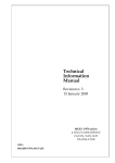
Fig. 1.1: Mod. V488 Block Diagram ...................................................................................... 3
Fig. 2.1: Mod. V488 Front Panel........................................................................................... 6
Fig. 2.2: Mod. V488 Components Locations ................................ ................................ .......... 7
Fig. 3.1: Mod. V488 Acquisition Sequences ................................ ................................ .......... 10
Fig. 3.2: Mod. V488 Full Scale Range Selection ....................................................................11
Fig. 3.3: Mod. V488 Output Buffer Data Packet FIFO Structure ............................................... 15
Fig. 4.1: Mod. V488 Base Address Setting............................................................................ 17
Fig. 4.2: Module Identifier Words ................................ ................................ .......................... 18
Fig. 4.3: Mod. V488 Control Register .................................................................................... 20
Fig. 4.4: Output Buffer Data Packet Header........................................................................... 21
Fig. 4.5: Output Buffer Channel Data.................................................................................... 21
Fig. 4.6: Mod. V488 Output Buffer Data Packet FIFO Structure ............................................... 22
Fig. 4.7: Mod. V488 Range Register ..................................................................................... 22
Fig. 4.8: Mod. V488 THRH Register ...................................................................................... 23
Fig. 4.9: Mod. V488 THRL Register....................................................................................... 23
Fig. 4.10: Mod. V488 Interrupt Register ................................................................................. 23
LIST OF TABLES
Table 4.1: Address Map for the Mod. V488 ............................................................................ 18
ii
26/02/2004
V488 User's Manual
PRELIMINARY
1. DESCRIPTION
1.1. FUNCTIONAL DESCRIPTION
The model V488 is a 1-unit wide VME module that houses 8 independent 12-bit Time to Digital
Conversion channels.
Each channel is build around a monolithic TAC (Time to Amplitude Converter) developed in
bipolar ASIC technology [1].
The outputs of the eight TAC sections are multiplexed and subsequently converted by a fast 12
bit ADC module (1 µsec conversion time).
The ADC module adopts a sliding scale technique [2-3] to decrease the differential linearity
error:
•
•
Differential non linearity
Integral non linearity
± 2%
± 0.1%
The Full Scale Time Range (common for all the channels) is programmable via VME, from 90
nsec to 770 nsec, with resolution from 25 to 200 psec respectively.
The board accepts 8 ECL inputs and one NIM common input (COM input). The COM is a high
impedance input and is provided with two bridged connectors for daisy chaining.
Two modes of operation programmable via VME:
Common Start:
Start on the COM signal
Stop on the corresponding input
signal
Common Stop:
Start on the corresponding input signal
Stop on the COM signal
The board houses a 12 bit counter (Event Counter) for the trigger counting; it is increased at
the occurrence of a valid event, i. e. with each COM pulse occurred when the module is not
BUSY.
Via VME is also possible:
•
•
to set a Low and High Threshold common for all the channels;
to enable /disable each TAC section.
Only the enabled channels that have a value that lies in between the two Thresholds are
converted and the result is stored in an Output Buffer that can be read via VME.
The Output Buffer is arranged in FIFO logic 512 x16 bit. The FIFO operation options are
programmable via VME (Stop conversions either when the FIFO is HALF FULL or when the
FIFO is FULL).
1
26/02/2004
V488 User's Manual
PRELIMINARY
The module houses a VME RORA INTERRUPTER[4]: via VME it is possible to program the
interrupt generation on the Output Buffer HALF FULL or on the Output Buffer NOT EMPTY.
A front panel LED (DTACK) lights up each time the module generates the VME signal DTACK.
An open-collector signal ("BUSY") is available on the front panel. This allows to obtain a wiredOR Global Busy signal. The BUSY is a high impedance out put and is provided with two
bridged connectors for daisy chaining.
The V488 Model uses the P1 and P2 connectors of VME and the auxiliary connector for the
CERN V430 VMEbus crate (Jaux Dataway)[5].
The module works in A24/A32 mode; the recognized Address Modifier codes are:
AM= %3D standard supervisor data access;
AM= %39 standard user data access;
AM= %0D extended supervisor data access;
AM= %09 extended user data access.
The module's Base Address is fixed by 6 internal rotary switches housed on two piggy-back
boards plugged into the main printed circuit board. The Base Address can be selected in the
range:
%00 0000
<--> %FF FF00
A24 mode;
%0000 0000 <--> %FFFF FF00 A32 mode.
The data transfer occurs in D16 mode.
2
26/02/2004
V488 User's Manual
PRELIMINARY
IDENTIFIER
INPUT 0
start
TAC
stop
VME
INPUT1
start
TAC
INTERFACE
stop
INPUT 2
start
TAC
stop
INPUT 3
start
TAC
stop
MUX
INPUT 4
OUTPUT
BUFFER
ADC
start
TAC
stop
INPUT 5
start
TAC
stop
INPUT 6
start
CONTROL LOGIC
TAC
stop
INPUT 7
start
IRQ
TAC
INTERRUPTER
stop
INT. LEVEL
STATUS /ID
COM
BUSY
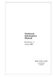
Fig. 1.1: Mod. V488 Block DiagramErrore. Il segnalibro non è definito.
3
26/02/2004
V488 User's Manual
PRELIMINARY
2. SPECIFICATIONS
2.1. PACKAGING
1-unit wide VME unit. Height: 6U.
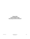
2.2. EXTERNAL COMPONENTS
(refer to fig. 2.1)
CONNECTORS
- N. 1, "IN 0..7", Input connector, Header 3M 3408-5202 type, 8+8 pins; for the 8 single
channel inputs.
- N. 2, "COM", LEMO 00 type; two bridged connectors (for daisy chaining) for the COMMON
input signal.
- N. 2, "BUSY", LEMO 00 type; two bridged connectors (for daisy chaining) for the BUSY
output signal .
DISPLAYS
- N. 1, "DTACK", green LED, VME Selected. It lights up during a VME access.
- N. 1, "COM START", red LED. It lights up when the module is in Common Start mode.
- N. 1, "COM STOP", red LED. It lights up when the module is in Common Stop mode.
2.3. INTERNAL COMPONENTS
(refer to fig. 2.2)
SWITCHES
- N. 6, rotary switches for the module's VME Base Address selection.
4
26/02/2004
V488 User's Manual
PRELIMINARY
2.4. CHARACTERISTICS OF THE SIGNALS
- INPUT CHANNELS:
std. differential ECL level, 110 Ω impedance;
min. width 5 ns;
- COM(1) :
std. NIM level, high impedance;
min. width 10 ns;
- BUSY:
std. TTL open collector output, active high.
(1) This is a high impedance input and is provided with two bridged connectors for daisy chaining. Note
that the high impedance makes this input sensitive to noise, so the chain has to be terminated on 50 Ω on
the last module; the same is needed also if one module only is used, whose input has thus to be properly
matched.
2.5. PERFORMANCES AND TEST RESULTS
- Differential non linearity
± 2%
- Integral non linearity
± 0.1%
Full Scale Time Range(2)
90 ns (min)
Resolution
25 ps
770 ns (max)
200 ps
(2) This is the standard configuration; it is possible to obtain different Full Scale Time Ranges by replacing few
components (up to a maximum of 4µs).
- Conversion time (3)
Min
3 µs
Max
13 µs
(3) This is the time spent in the entire conversion sequence (see § 3.2); the minimum value is obtained when all
the 8 TAC values are not in the range selected and hence there is no ADC conversions. Substantially it is the
Control Logic scan time. The maximum value is obtained when all the 8 TAC values are in the range selected and
therefore converted and stored in the Output Buffer.
2.6. POWER REQUIREMENTS
+ 12 V
− 12 V
+5V
−5V
300 mA
100 mA
1.0 A
1.1 A
5
26/02/2004
V488 User's Manual
PRELIMINARY
Mod. V560E
Mod. V488
COM
START
COMMON START LED
COMMON STOP LED
COM
STOP
− +
7
Inputs 0..7
0
IN
COM input
C
O
M
D
T
A
C
K
BUSY output
VME selected LED
B
U
S
Y
16 CH
SCALER
8 CH
TDC
Fig. 2.1: Mod. V488 Front PanelErrore. Il segnalibro non è definito.
6
26/02/2004
V488 User's Manual
PRELIMINARY
Rotary switches
for Base address selection
Component side of the board
Fig. 2.2: Mod. V488 Components LocationsErrore. Il segnalibro non è definito.
7
26/02/2004
V488 User's Manual
PRELIMINARY
3. OPERATING MODES
3.1. INTRODUCTION
The module V488 houses 8 Time to Amplitude Conversion (TAC) channels which can operate
in Common Start or Common Stop mode. The Full Scale Time Range is programmable via
VME. The TAC outputs are multiplexed and subsequently converted by a high speed ADC
module. A Control Logic controls the conversion sequence; it converts and stores in the Output
Buffer only the channels that have values lying in a range defined by a High and Low Threshold.
The module is Busy during the conversion sequence and when the Output Buffer is not ready
to accept data (Buffer full).
When the module is Busy it sets to TTL logic level "1" the Busy output. Moreover each
channel can be individually inhibited via VME.
3.2. OPERATION SEQUENCE
3.2.1.COMMON START SEQUENCE
If the module is not Busy and if at least one channel is enabled, a NIM pulse on the COM input
causes the following:
•
•
•
•
starts the TAC conversion of the enabled channels;
increments the Event Counter;
sets the BUSY output to 1 (Module Busy);
starts the Control Logic Time-Out Counter.
The Control Logic waits until the Time-Out Counter reaches the selected Full Scale Time
Range; during this time an ECL pulse on any input stops the corresponding TAC section.
When the Time-out counter reaches the full scale time, the Control Logic starts the conversion
sequence:
•
•
•
•
the output of the TAC sections are sampled;
the Control Logic checks if the sampled values are in the selected range;
If at least one value is lying in the range:
- a header is stored in the Output Buffer; it contains the event counter value and the
number of the channels in the range;
- the sampled values in the range are converted and the 12 bit values obtained are
stored in the Output Buffer together with the corresponding channel number.
if no value is lying in the range no channel is converted and no data are written in the
Output Buffer.
The Busy is removed and the module is ready for the next Common Stop acquisition.
3.2.2.COMMON STOP SEQUENCE
8
26/02/2004
V488 User's Manual
PRELIMINARY
An ECL pulse on any input:
•
starts the conversion of the corresponding TAC sections (if enabled).
A NIM pulse on the COM input:
•
•
•
•
stops the TAC conversions;
increments the Event Counter;
sets the BUSY output to 1 (Module Busy);
causes the Control Logic to start the conversion sequence.
The Control Logic performs the conversion sequence:
•
•
•
•
the output of the TAC sections are sampled;
the Control Logic checks if the sampled values are in the selected range;
If at least one value is lying in the range:
- a header is stored in the Output Buffer; it contains the event counter value and the
number of the channels in the range;
- the sampled values in the range are converted and the 12 bit values obtained are
stored in the Output Buffer together with the corresponding channel number.
if no value is lying in the range no channel is converted and no data are written in the
Output Buffer.
The Busy is removed and the module is ready for the next Common Start acquisition.
The two operation sequences previously described are summarized in Figure 3.1.
9
26/02/2004
V488 User's Manual
PRELIMINARY
Full Scale Time
COMMON START:
tn+1
Conversion Time
tn
COM
input n
input n+1
BUSY
Event Counter
m
Start
TACs
COMMON STOP:
m+1
Stop
TAC n
Stop
TAC n+1
tn+1
Start conv.
End conv.
sequence
sequence
Conversion Time
tn
COM
input n
input n+1
BUSY
Event Counter
Start
TAC n
m
Start
TAC n+1
m+1
Stop
TACs
Start conv.
sequence
End conv.
sequence
Fig. 3.1: Mod. V488 Acquisition SequencesErrore. Il segnalibro non è definito.
10
26/02/2004
V488 User's Manual
PRELIMINARY
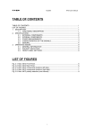
3.3. FULL SCALE TIME RANGE SELECTION
Via VME, it is possible to program the Full Scale Time Range in common to all the channels.
In the Standard configuration it can be set from 90 nsec to 770 nsec.
The different ranges are selected via the Range Register that is available at the VME address
Base + %14 (see § 4.7). The suggested values range from %00, corresponding to 90 nsec, up
to %E0, corresponding to 770 nsec. The different values can be selected according to the
curve shown in Fig. 3.2: given a value N of the programmed range, the corresponding Time
Range is:
Time Range = 3840/GAIN(N)
GAIN (counts/ns)
45
40
35
30
25
20
15
10
5
0
e0
d0
c0
b0
a0
90
80
70
60
50
40
30
20
10
0
PROGRAMMED VALUE (N)
Fig. 3.2: Mod. V488 Full Scale Range SelectionErrore. Il segnalibro non è definito.
3.4. OPERATION MODE SELECTION
Two operation modes are programmable via VME:
Common Start:
Start on the COM signal
Stop on the corresponding input signal
Common Stop:
Start on the corresponding input signal
Stop on the COM signal
The operation mode is controlled by the bit 15 of the Control Register:
•
•
Control Register <15> = 0 → Common Start mode;
Control Register <15> = 1 → Common Stop mode.
The Control Register is available at the VME address Base + %1A.
11
26/02/2004
V488 User's Manual
PRELIMINARY
3.5. ENABLE/DISABLE CHANNEL OPERATION
Via VME It is possible to enable/disable the TAC section of each channel; the bits <7..0> of
the Control Register allow to set the status of the 8 TAC sections:
•
•
Control Register <n> = 0 → channel n TAC disabled;
Control Register <n> = 1 → channel n TAC enabled.
The Control Register is available at the VME address Base + %1A.
All the TAC sections are disabled (Control Register <7..0> cleared) in the following cases:
•
•
•
by acces sing via VME the address Base + %1C (Reset Register);
upon generation of the VME signal SYSRES;
at Power-On.
3.6. LOW AND HIGH THRESHOLD SETTING
The Control Logic converts and stores in the Output Buffer only the channels that have values
lying in a range identified by a High and Low Threshold. This feature allows the Zero
Suppression of undesired time values.
The Threshold values are 8 bit wide and are programmable via VME by accessing in write two
write only registers:
•
•
Low Threshold register (THRL)
High Threshold register (THRH)
VME address = Base + %10
VME address = Base + %12
3.7. ADC DYNAMIC RANGE
The sliding scale correction reduces slightly the dynamic range of the ADC; the 12 bit digital
output is valid from 0 to 3840; values from 3841 to 4095 are not correct.
The usable range of the analog input of the ADC is ≈ 0.15 V to 3.75 V. The conversion of an
analog input that is greater than the upper limit could lead to an unpredictable digital output
coding in the range from 0 to 255. The User should use the high threshold to maintain the
analog input of the ADC below this upper limit.
The recommended High Threshold values are less than %C7 (hex).
12
26/02/2004
V488 User's Manual
PRELIMINARY
3.8. COM INPUT
COMMON START MODE
If the module is not BUSY, a NIM pulse on the COM input (trigger) causes the following:
•
•
•
•
starts the TAC conversion of the enabled channels;
increments the Event Counter;
sets the BUSY output to 1 (Module Busy);
starts the Control logic Time-Out Counter.
COMMON STOP MODE
If the module is not BUSY, a NIM pulse on the COM input (trigger):
•
•
•
•
stops the TAC conversions of the enabled channels;
increments the Event Counter;
sets the BUSY output to 1 (Module Busy);
causes the Control Logic to start the conversion sequence.
This is a high impedance input and is provided with two bridged connectors for daisy chaining;
this allows to control easily a system of many units.
Note that the high impedance makes this input sensitive to noise, so the chain has to be
terminated on 50 Ω on the last module; the same is needed also if one module only is used,
whose inputs have thus to be properly matched.
3.9. BUSY OUTPUT
An open-collector signal ("BUSY"), active high, is available on the front panel. It is a high
impedance output and is provided with two bridged connectors for daisy chaining: this allows to
obtain a wired-or Global Busy signal of a system composed of many units.
Each module sets to 1 its Busy output after a pulse on the COM input (Module Busy) and
releases it to 0 at the end of the conversion sequence. When the Module is Busy it does not
accept another COM pulse (Trigger). The same happens also if the FIFO cannot accept more
data.
If many units are connected in daisy chain mode via the COM and BUSY signals, after a pulse
on the COM input (trigger) the Global Busy signal is set to 1 and it is released to 0 only when
all the V488 modules in the chain have completed the conversion sequence and the entire
system is ready to accept another trigger.
This avoids that some modules in the chain could accept another trigger while other modules
are still Busy. This may cause a lack of coherence in the overall data (the event counter values
of different module could not be coherent).
This feature allows to mix in the same system modules with different Full Scale Time Ranges
without problem, and ensures that data related to the same trigger number in different modules
belong to the same physical trigger.
13
26/02/2004
V488 User's Manual
PRELIMINARY
3.10. RESET OPERATION
A pulse through the RESET input sets the board in the following state:
1.
2.
3.
4.
5.
6.
7.
8.
the event counter is set to 0;
the output buffer is reset (FIFO EMPTY);
all the channels are disabled (Control Register <7..0> cleared);
the Range is set to 0;
the Output Buffer is set to the HF mode;
the Interrupt start condition is set to 0 (Interrupt on buffer Half Full);
the Interrupt level is set to 0;
the module operation is set to Common Start mode.
After a reset the module must be initialized again.
The VME Reset (access to address Base + %1C) and the generation of the VME signal
SYSRES perform the same actions.
3.11. OUTPUT BUFFER OPERATION MODES
The output buffer is arranged in FIFO logic 512 x16 bit.
Two operation modes are programmable via VME:
HF (Half Full) mode: The Module does not accept any trigger (Module BUSY) when the
number of data stored is greater than the half-size of the FIFO.
FF (FIFO Full) mode: The Module does not accept any trigger (Module BUSY) when the FIFO
is full. In this operating mode it is possible to use all the memory locations, but it is possible to
lose some data (if the FIFO becomes full during a conversion sequence).
The mode selection is done via the bit 12 of the Range Register:
Range Registrer<12> = 1 → FIFO FULL Mode
Range Registrer<12> = 0 → FIFO HALF FULL Mode
3.12. OUTPUT BUFFER STRUCTURE
During the conversion sequence, if at least one TAC output value is lying in the range identified
by the High and Low Thresholds, the Control Logic stores in the Output Buffer the following
words:
•
•
a header that contains the event counter value and the number of the channels in the
range; this number also indicates the number of subsequent words in the FIFO related
to that event;
the 12 bit converted time values together with the corresponding channel number.
If no channel is in the correct range the Output Buffer is not written.
The Output Buffer is available at VME address BASE + % 18.
14
26/02/2004
V488 User's Manual
PRELIMINARY
The bit 15 of the Output Buffer indicates if the word read is a header or a channel data:
•
•
Output Buffer <15> =1 → header
Output Buffer <15> =0 → channel data
The status of the Output Buffer is available in the Control Register:
•
•
•
Control Register <12> = 0 → Output Buffer is Half full;
Control Register <13> = 0 → Output Buffer is Full;
Control Register <14> = 0 → Output Buffer is Empty.
The following figure shows an example of the Output Buffer structure:
•
•
•
•
The first datum written is HEADER 5;
In the Trigger n. 5 two channels (2 and 5) were in the selected range;
In the Trigger n. 6 and n. 7 no channel was in the selected range;
In the Trigger n. 8 three channels (0, 1 and 3) were in the selected range.
15 14 13 12 11 10 9 8 7 6 5 4 3 2 1 0
Trigger nr.5
ch.2 and ch.5 converted
Trigger nr.8
ch.0,ch.1and ch.3 converted
H E A D E R 5
Event cnt. = 5 Mult. = 1
D a t u m
c h a n n e l
2
D a t u m
c h a n n e l
5
H E A D E R 8
trigger 6 and 7:
no channel converted
Event cnt. = 8 Mult. = 2
D a t u m
c h a n n e l
0
D a t u m
c h a n n e l
1
D a t u m
c h a n n e l
3
Fig. 3.3: Mod. V488 Output Buffer Data Packet FIFO StructureErrore. Il segnalibro non
è definito.
3.13. INTERRUPT GENERATION
The operations of the V488 VME INTERRUPTER are fully programmable; via VME it is
possible:
•
•
•
to set the VME Interrupt level;
to program the VME Interrupt Vector (STATUS/ID);
to program the Interrupt Generation on the Output Buffer HALF FULL or on the Output
Buffer NOT EMPTY; this is controlled by the bit 12 of the Interrupt Register:
•
•
Interrupt Register<12> = 0
Interrupt Register <12> = 1
Interrupt on Output Buffer HALF FULL;
Interrupt on Output Buffer NOT EMPTY.
15
26/02/2004
V488 User's Manual
PRELIMINARY
4. VME INTERFACE
4.1. ADDRESSING CAPABILITY
The module works in A24/A32 mode. This implies that the module's address must be specified
in a field of 24 or 32 bits. The Address Modifiers code recognized by the module are:
AM=%3D:
AM=%39:
AM=%0D
AM=%09:
standard supervisor data access
standard user data access
extended supervisor program access
extended user data access
The module's Base Address is fixed by 6 internal rotary switches housed on two piggy-back
boards plugged into the main printed circuit board.
The Base Address can be selected in the range:
% 00 0000 <-> % FF FF00
A24 mode
% 0000 0000 <->% FFFF FF00 A32 mode
The Base Address reserves in this way a page of 256 bytes for the module. The Address Map
of the page is shown in table 4.1 on the following page.
4.2. DATA TRANSFER CAPABILITY
The internal registers and the Output Buffer are accessible in D16 mode.
16
26/02/2004
V488 User's Manual
PRELIMINARY
Base address bit <23..20>
Base address bit <19..16>
Base address bit <15..12>
Base address bit <11..8>
Base address bit <31..28>
Base address bit <27..24>
Fig. 4.1: Mod. V488 Base Address SettingErrore. Il segnalibro non è definito.
17
26/02/2004
V488 User's Manual
PRELIMINARY
Table 4.1: Address Map for the Mod. V488Errore. Il segnalibro non è definito.
ADDRESS
REGISTER/CONTENT
Base + %FE
Base + %FC
Base + %FA
Version & Series
Manufacturer & Module type
Fixed Code
Base + %F8
.
.
Base + %20
Not used
.
.
Not used
Base + %1E
Base + %1C
Base + %1A
Base + %18
Base + %16
Base + %14
Base + %12
Base + %10
HF Register
Reset Register
Control Register
Output Buffer
FF Register
Range Register
THRH Register
THRL Register
Base + %0E
.
.
Base + %02
Not used
.
.
Not used
Base + %00
Interrupt Register
TYPE
read only
read only
read only
read/write
read/write
read/write
read only
read/write
read/write
write only
write only
read/write
4.3. MODULE IDENTIFIER WORDS
(Base address + %FA ,+%FC, +%FE read only)
The Three words located at the highest address on the page are used to identify the module as
shown in figure 4.2:
15 14 13 12 11 10 9
V e r s i o n
7
6
5
4
3
2
M o d u l e ' s s e r i a l n u m b e r
Manufacturer number
% F A
8
M o d u l e t y p e
F i x e d c o d e
% F 5
F i x e d c o d e
1
0
Address
Base + % FE
Base + % FC
Base + % FA
Fig. 4.2: Module Identifier WordsErrore. Il segnalibro non è definito.
At the address Base + % FA the two particular bytes allow the automatic localization of the
module.
For the Mod. V488 the word at address Base + % FC has the following configuration:
Manufacturer N°=
Type of module =
000010 b
0000010111 b
18
26/02/2004
V488 User's Manual
PRELIMINARY
The word located at the address Base + %FE identifies the single module via a serial number,
and any change in the hardware (for example the use of faster Conversion Logic) will be shown
by the Version number.
4.4. HF REGISTER
(Base address + %1E read/write)
A VME access (read or write) to this location sets the Output Buffer in the HALF FULL mode;
the mode selection is available in read only mode at the bit 12 of the Range Register.
•
•
Range Register <12>=0
Range Register <12>=1
HF mode;
FF mode.
4.5. RESET REGISTER
(Base address + %1C read/write)
A VME access (read or write) to this location causes the following:
1.
2.
3.
4.
5.
6.
7.
8.
the event counter is set to 0;
the output buffer is reset (FIFO EMPTY);
all the channels are disabled (Control Register <7..0> cleared);
the Range is set to 0;
the Output Buffer is set to the HF mode;
the Interrupt start condition is set to 0 (Interrupt on buffer Half Full);
the Interrupt level is set to 0;
the module operation is set to Common Start mode.
The same action are performed if the VME signal SYSRES is active.
19
26/02/2004
V488 User's Manual
PRELIMINARY
4.6. CONTROL REGISTER
(Base address + %1A read/write)
15 14 13 12 11 10 9
ST
/FE
/FF
/HF
8
7
6
5
4
3
2
1
0
E7
E6
E5
E4
E3
E2
E1
E0
Enable ch. 0
Enable ch. 1
Enable ch. 2
Enable ch. 3
Enable ch. 4
Enable ch. 5
Enable ch. 6
Enable ch. 7
FIFO HALF FULL read only
FIFO FULL read only
FIFOEMPTY read only
Status Start/Stop
Fig. 4.3: Mod. V488 Control RegisterErrore. Il segnalibro non è definito.
E<7..0>
Enable channel <7..0>:
=0
channel n TAC disabled;
=1
channel n TAC enabled.
These bits are cleared in the following cases:
- by accessing via VME the address Base + %1C (Reset Register);
- by generating the VME signal SYSRES;
- at Power-On.
/HF
Output Buffer half full bit read only.
=0
Output Buffer is half full;
/FF
Output Buffer full bit read only.
=0
Output Buffer is full;
/FE
Output Buffer empty bit read only.
=0
Output Buffer is empty;
ST
Operation mode selection bit.
=0
Common Start mode;
=1
Common Stop mode.
(Bits 8 to 11 are unused and are read as "one" on the VME data bus).
20
26/02/2004
V488 User's Manual
PRELIMINARY
4.7. OUTPUT BUFFER
(Base address + %18 read only)
The Output Buffer is arranged in FIFO logic 512 x16 bit (expandable on request).
In this Buffer are available the data packets stored during the conversion sequence, if at least
one TAC output value is lying in the selected range.
The first word of the packet is a header; it contains the event counter value and the number of
the channels in the range; this number also indicates the data packet length.
The other word contains the 12 bit converted time values together with the corresponding
channel number.
The bit 15 of the word distinguishes between header and channel data:
Output Buffer <15> =1 → header
Output Buffer <15> =0 → channel data
•
•
15 14 13 12 11 10 9
1
M U L T.
8
7
6
5
4
3
2
1
0
EVENT COUNTER
Event Counter value
Number of channels converted -1
Fig. 4.4: Output Buffer Data Packet HeaderErrore. Il segnalibro non è definito.
EVENT CNT. 12 bit Event Counter.
It counts the pulse on the COM input; it is inhibited if the Module is Busy.
MULT
Multiplicity.
It indicates the number of channels in the range:
MULT+1 =number of channel, i.e., the packet length (MULT=0: one channel).
15 14 13 12 11 10 9
0
CH. NUM.
8
7
6
5
4
3
2
1
0
CHANNEL DATA
12 bit Channel data
Channel number
Fig. 4.5: Mod. V488 Output Buffer Channel DataErrore. Il segnalibro non è definito.
21
26/02/2004
V488 User's Manual
PRELIMINARY
The following figure shows an example of the Output Buffer structure:
•
•
•
•
The first datum written is HEADER 5;
In the Trigger n. 5 two channels (2 and 5) were in the selected range;
In the Trigger n. 6 and n. 7 no channel was in the selected range;
In the Trigger n. 8 three channels (0, 1 and 3) were in the selected range.
First datum read:
15 14 13 12 11 10 9 8 7 6 5 4 3 2 1 0
H E A D E R 5
Trigger nr.5
Event cnt. = 5 Mult. = 1
D a t u m c h a n n e l 2
ch.2 and ch.5 converted
trigger 6 and 7:
D a t u m c h a n n e l 5
no channel converted
H E A D E R 8
Trigger nr.8
Event cnt. = 8 Mult. = 2
D a t u m c h a n n e l 0
ch.0,ch.1and ch.3 converted
D a t u m c h a n n e l 1
D a t u m c h a n n e l 3
Fig. 4.6: Mod. V488 Output Buffer Data Packet FIFO StructureErrore. Il segnalibro non
è definito.
4.8. FF REGISTER
(Base address + %16 read/write)
A VME access (read or write) to this location sets the Output Buffer in the FIFO FULL mode;
the mode selection is available in read only mode at the bit 12 of the Range Register (see §
4.9) .
4.9. RANGE REGISTER
(Base address + %14 read/write)
The bits <7..0> of the Range Register allow to select the Full Scale Time Range in common for
all the channels. Suggested values range from %00 to %E0, corresponding respectively to 90
ns and 770 ns. The bits <7..0> are available in write only mode. Bit 12 is available in read only
mode and represents the status of the FIFO operating mode:
• Range Register <12>=0
HF mode
• Range Register <12>=1
FF mode
During a read access, the bits <7..0> contain fake data, while the upper bits (except bit 12)
will contain zeroes.
15 14 13 12 11 10 9
8
7
6
5
FM
4
3
2
1
0
RANGE
FIFO Mode (0=HF, 1=FF)
22
Full Scale
Time Range
26/02/2004
V488 User's Manual
PRELIMINARY
Fig. 4.7: Mod. V488 Range RegisterErrore. Il segnalibro non è definito.
23
26/02/2004
V488 User's Manual
PRELIMINARY
4.10. THRH REGISTER
(Base address + %12 write only)
This register (High Threshold register) allows to set the 8 bit value of the High Threshold.
The usable range of the analog input of the ADC is ≈ 0.15 V to 3.75 V. The conversion of an
analog input that is greater than the upper limit could lead to an unpredictable digital output
coding in the range from 0 to 255. The User should use the High Threshold to maintain the
analog input of the ADC under this upper limit.
The recommended High Threshold values are less than %C7 (hex).
15 14 13 12 11 10 9
8
7
6
5
4
3
2
1
0
HIGH THRESHOLD.
Fig. 4.8: Mod. V488 THRH RegisterErrore. Il segnalibro non è definito.
4.11. THRL REGISTER
(Base address + %10 write only)
This register (Low Threshold register) allows to set the 8 bit value of the Low Threshold. This
value must be smaller than the High Threshold value.
15 14 13 12 11 10 9
8
7
6
5
4
3
2
1
0
LOW THRESHOLD.
Fig. 4.9: Mod. V488 THRL RegisterErrore. Il segnalibro non è definito.
4.12. INTERRUPT REGISTER
(Base address + %0 read/write)
This register contains the value of the Interrupt Level and the STATUS/ID that the V488
INTERRUPTER places on the VME data bus during the Interrupt Acknowledge cycle.
(Bits 8 to 11 are unused and are read as "one" on the VME data bus).
15 14 13 12 11 10 9
INT. LEV.
INT
8
7
6
5
4
3
2
1
0
STATUS /I D
Interrupt STATUS/ID
Interrupt start condition
Interrupt level
Fig. 4.10: Mod. V488 Interrupt RegisterErrore. Il segnalibro non è definito.
INT
Interrupt start condition:
=0
Interrupt on Output Buffer HALF FULL;
24
26/02/2004
V488 User's Manual
PRELIMINARY
=1
Interrupt on Output Buffer NOT EMPTY.
25
26/02/2004
V488 User's Manual
PRELIMINARY
5. MOD. V488 INTERRUPTER
5.1. INTERRUPTER CAPABILITY
The Mod. V488 houses a VME RORA INTERRUPTER D08(o) type. This implies the following:
• it responds to 8 bit, 16 bit and 32 bit interrupt acknowledge cycles providing an 8-bit
STATUS/ID on the VME data lines D00..D07;
• it removes its interrupt request when some on board registers are accessed by a VME
MASTER (RORA: Release On Register Access).
5.2. INTERRUPT LEVEL
The interrupt level corresponds to the value stored in the Interrupt Register <15..13>. The
register is available at the VME address Base + % 00.
5.3. INTERRUPT STATUS/ID
The interrupt STATUS/ID is 8 bit wide, and it is contained in the Interrupt Register<7..0>
(address Base + % 00).
5.4. INTERRUPT GENERATION
Via VME it is possible to program the Interrupt Generation on the Output Buffer HALF FULL or
on the Output Buffer NOT EMPTY; this is controlled by the bit 12 of the Interrupt Register:
•
•
Interrupt Register<12> = 0
Interrupt Register <12> = 1
Interrupt on Output Buffer HALF FULL;
Interrupt on Output Buffer NOT EMPTY.
5.5. INTERRUPT REQUEST RELEASE
The V488 INTERRUPTER removes its Interrupt request depending on the selected operating
mode, according to the following:
1.
If FIFO NOT EMPTY mode is selected, by reading out the FIFO until it doesn't become
EMPTY;
2.
If FIFO HALF FULL mode is selected, by reading out the FIFO until it doesn't become less
than HALF FULL.
5.6. INTERRUPT SEQUENCE
26
26/02/2004
V488 User's Manual
PRELIMINARY
{
- if the FIFO becomes NOT EMPTY or HALF FULL (according to selected mode):
{
- it requests interrupt by driving an Interrupt Request line IRQ1..7 low according
to the Interrupt Register <15..13> value;
- during the subsequent acknowledge cycle it places on the VME data lines
D00..D07 the STATUS/ID; it is the byte contained in the 8 LSB of the Interrupt
register (address Base +% 00);
}
- if a VME MASTER accesses the FIFO it releases the VME interrupt request line once
the Interrupt condition is removed (FIFO EMPTY if FIFO NOT EMPTY mode was
selected or FIFO NOT EMPTY if FIFO HALF FULL was selected).
}
27
26/02/2004
V488 User's Manual
PRELIMINARY
6. REFERENCES
[1] J. Pouxe, "Time to Amplitude Converter ASIC", ISN Grenoble, June 1990.
[2] C. Cottini, E. Gatti, V. Svelto, "A new method of analog to digital conversion", NIM vol.24 p.
241, 1963.
[3] C. Cottini, E. Gatti, V. Svelto, " A sliding scale analog to digital converter for pulse height
analysis", in Proc. Int. Symp. Nuclear, Paris, Nov. 1963.
[4] VMEbus Specification Manual Revision C.1, October 1985.
[5] G. Bianchetti et al., "Specification for VMEbus CRATE Type V430", CERN-EP, January
1990.
28
26/02/2004
V488 User's Manual
PRELIMINARY
APPENDIX A: ELECTRICAL DIAGRAMS
A.1