1
ADDRESS SPACES
S3C828B/F828B/C8289/F8289/C8285/F8285
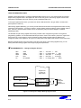
USING THE REGISTER POINTS
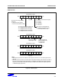
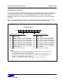
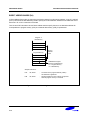
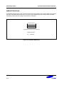
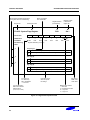
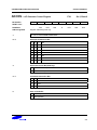
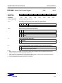
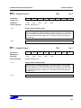
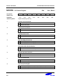
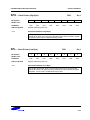
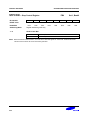
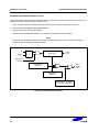
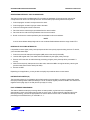
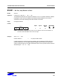
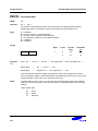
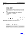
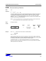
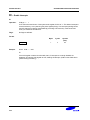
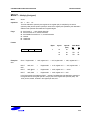
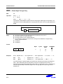
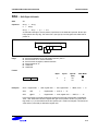
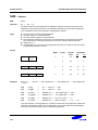
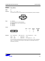
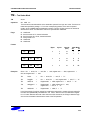
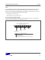
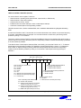
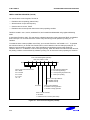
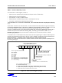
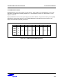
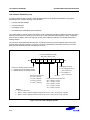
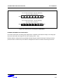
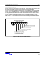
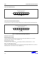
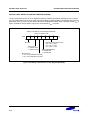
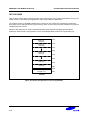
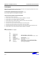
Register pointers RP0 and RP1, mapped to addresses D6H and D7H in set 1, are used to select two movable
8-byte working register slices in the register file. After a reset, they point to the working register common area:
RP0 points to addresses C0H–C7H, and RP1 points to addresses C8H–CFH.
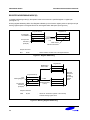
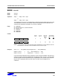
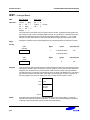
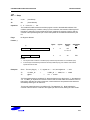
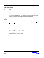
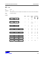
To change a register pointer value, you load a new value to RP0 and/or RP1 using an SRP or LD instruction.
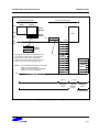
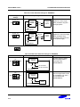
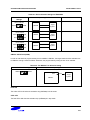
(see Figures 2-9 and 2-10).
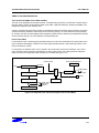
With working register addressing, you can only access those two 8-bit slices of the register file that are currently
pointed to by RP0 and RP1. You cannot, however, use the register pointers to select a working register space in
set 2, C0H–FFH, because these locations can be accessed only using the Indirect Register or Indexed
addressing modes.
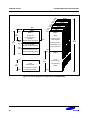
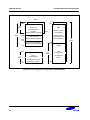
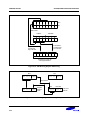
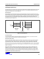
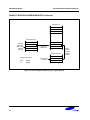
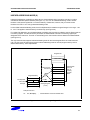
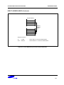
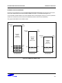
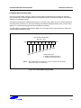
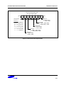
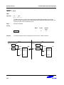
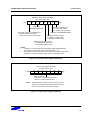
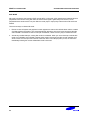
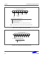
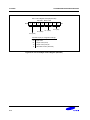
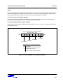
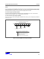
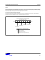
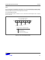
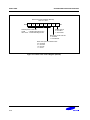
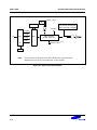
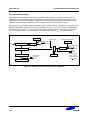
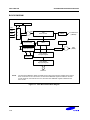
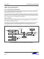
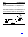
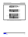
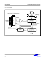
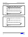
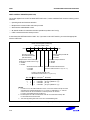
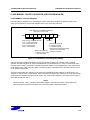
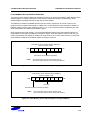
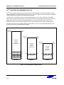
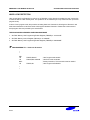
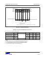
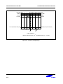
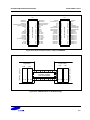
The selected 16-byte working register block usually consists of two contiguous 8-byte slices. As a general
programming guideline, it is recommended that RP0 point to the "lower" slice and RP1 point to the "upper" slice
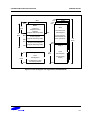
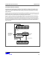
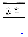
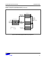
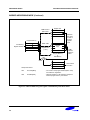
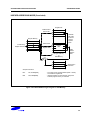
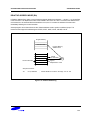
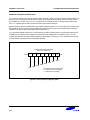
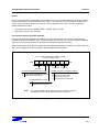
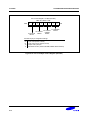
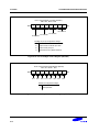
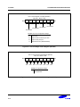
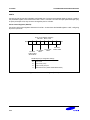
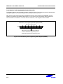
(see Figure 2-9). In some cases, it may be necessary to define working register areas in different (noncontiguous) areas of the register file. In Figure 2-10, RP0 points to the "upper" slice and RP1 to the "lower" slice.
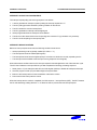
Because a register pointer can point to either of the two 8-byte slices in the working register block, you can
flexibly define the working register area to support program requirements.
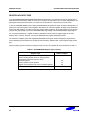
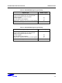
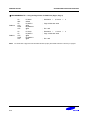
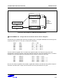
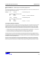
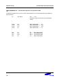
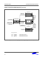
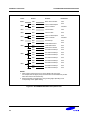
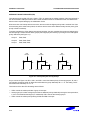
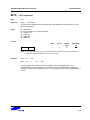
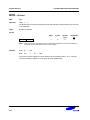
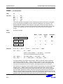
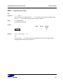
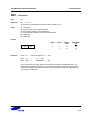
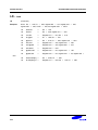
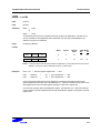
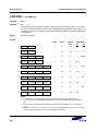
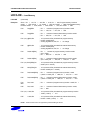
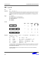
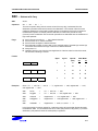
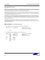
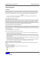
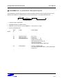
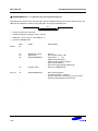
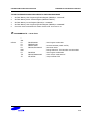
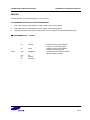
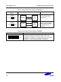
PROGRAMMING TIP — Setting the Register Pointers
SRP
SRP1
SRP0
CLR
LD
#70H
#48H
#0A0H
RP0
RP1,#0F8H
;
;
;
;
;
RP0
RP0
RP0
RP0
RP0
←
←
←
←
←
70H, RP1 ← 78H
no change, RP1 ← 48H,
A0H, RP1 ← no change
00H, RP1 ← no change
no change, RP1 ← 0F8H
Register File
Contains 32
8-Byte Slices
0 0 0 0 1 X X X
8-Byte Slice
RP1
0 0 0 0 0 X X X
8-Byte Slice
FH (R15)
8H
7H
0H (R0)
RP0
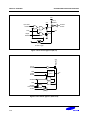
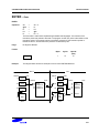
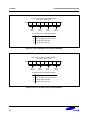
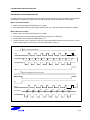
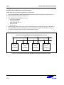
Figure 2-9. Contiguous 16-Byte Working Register Block
2-14
16-Byte
Contiguous
Working
Register block