1
Hardware Installation Guide
6
7
8
Product Model : DGS-6600 Series
Layer 3 Chassis Ethernet Managed Switch
Release 3.0
DGS-6600 Layer 3 Chassis Ethernet Managed Switch Hardware Installation Guide
Information in this document is subject to change without notice.
© 2013 D-Link Corporation. All rights reserved.
Reproduction in any manner whatsoever without the written permission of D-Link Corporation is strictly forbidden.
Trademarks used in this text: D-Link and the D-LINK logo are trademarks of D-Link Corporation; Microsoft and Windows are registered trademarks of
Microsoft Corporation.
Other trademarks and trade names may be used in this document to refer to either the entities claiming the marks and names or their products. D-Link
Corporation disclaims any proprietary interest in trademarks and trade names other than its own.
January 2013 P/N 651GS6604035G
FCC Warning
This equipment has been tested and found to comply with the limits for a Class A digital device, pursuant to Part
15 of the FCC rules. These limits are designed to provide reasonable protection against harmful interference
when the equipment is operated in a commercial environment. This equipment generates, uses, and can radiate
radio frequency energy, and, if not installed and used in accordance with this manual, may cause harmful
interference to radio communications. Operation of this equipment in a residential area is likely to cause harmful
interference in which case the user will be required to correct the interference at their own expense.
CE Mark Warning
This is a Class A product. In a domestic environment, this product may cause radio interference in which case
the user may be required to take adequate measures.
Warnung!
Dies ist ein Produkt der Klasse A. Im Wohnbereich kann dieses Produkt Funkstoerungen verursachen. In diesem
Fall kann vom Benutzer verlangt werden, angemessene Massnahmen zu ergreifen.
Precaución!
Este es un producto de Clase A. En un entorno doméstico, puede causar interferencias de radio, en cuyo case,
puede requerirse al usuario para que adopte las medidas adecuadas.
Attention!
Ceci est un produit de classe A. Dans un environnement domestique, ce produit pourrait causer des
interférences radio, auquel cas l`utilisateur devrait prendre les mesures adéquates.
Attenzione!
Il presente prodotto appartiene alla classe A. Se utilizzato in ambiente domestico il prodotto può causare
interferenze radio, nel cui caso è possibile che l`utente debba assumere provvedimenti adeguati.
VCCI Warning
BSMI
此為甲類的資訊技術設備,在居住環境中使用時,可能會造成射頻擾動,在這種情況下,使用者會被要求採取某些適當的對
策。
仅适用于海拔2000米以下地区安全使用
iii
DGS-6600 Layer 3 Chassis Ethernet Managed Switch Hardware Installation Guide
Intended Readers...............................................................................................................................................vii
Typographical Conventions................................................................................................................................vii
Notes, Notices, and Cautions.............................................................................................................................ix
Safety Suggestions ............................................................................................................................................ix
Safety Recommendations for Handling the Switch.......................................................................................ix
Safety Recommendations for Removing and replacing Batteries.................................................................ix
Safety Precautions for Installing and Removing the Switch..........................................................................x
Electrical Safety ............................................................................................................................................x
Laser Safety..................................................................................................................................................xiii
Chapter 1 Introduction .......................................................................................................... 1
DGS-6600 Series Switch Description ................................................................................................................1
DGS-6604 Product Specifications......................................................................................................................1
Product Features ..........................................................................................................................................1
DGS-6604 Product Appearance ........................................................................................................................3
DGS-6604 Hardware Composition.....................................................................................................................4
Chassis .........................................................................................................................................................4
Module Plug-in Frame...................................................................................................................................4
DGS-6604 Ventilation/Heat Dissipation System ................................................................................................5
DGS-6608 Product Specifications......................................................................................................................5
Product Features ..........................................................................................................................................5
DGS-6608 Product Appearance ........................................................................................................................7
DGS-6608 Hardware Composition.....................................................................................................................8
Chassis .........................................................................................................................................................8
Module Plug-in Frame...................................................................................................................................8
DGS-6608 Ventilation/Heat Dissipation System ................................................................................................9
DGS-6600 CPU & I/O Modules..........................................................................................................................10
DGS-6600-CM Module .................................................................................................................................11
DGS-6600-CM-II management module: .......................................................................................................14
DGS-6600-24SC2XS Module .......................................................................................................................17
DGS-6600-16XS-D .......................................................................................................................................19
DGS-6600-48P Module.................................................................................................................................21
DGS-6600-48S Module.................................................................................................................................24
DGS-6600-48T Module.................................................................................................................................26
DGS-6600-48TS Module ..............................................................................................................................28
DGS-6600-8XG Module................................................................................................................................31
Chapter 2 Installation ............................................................................................................ 33
Installation Site Requirements ...........................................................................................................................33
Rack Mounting Requirements.......................................................................................................................33
Ventilation Requirements..............................................................................................................................34
Power Requirements ....................................................................................................................................35
System Grounding Requirements.................................................................................................................35
Safety Grounding ..........................................................................................................................................35
Lightning Grounding......................................................................................................................................35
EMI Considerations.......................................................................................................................................36
Precautions for Fiber Connections................................................................................................................37
Installation Tool Requirements...........................................................................................................................37
Inspection Requirements when Unpacking the Switch ......................................................................................37
Inventory .......................................................................................................................................................37
Installation Flowchart .........................................................................................................................................38
Verifying the Installation .....................................................................................................................................38
Installing the Cabinet..........................................................................................................................................39
Cabinet Installation Precautions ...................................................................................................................39
iv
DGS-6600 Layer 3 Chassis Ethernet Managed Switch Hardware Installation Guide
Simple Installation Steps...............................................................................................................................40
Mounting the DGS-6600 Series Switch into the Cabinet ...................................................................................40
Fan Tray Installation...........................................................................................................................................41
Power Supply Installation...................................................................................................................................43
Air Filter Installation............................................................................................................................................44
System Ground Connection ...............................................................................................................................45
Grounding Precautions .................................................................................................................................45
Simple Grounding Steps ...............................................................................................................................45
Connecting the AC Power Supply to the Power Module....................................................................................46
AC Power Supply Connection Precautions...................................................................................................46
Simple AC Power Connection Steps ............................................................................................................46
Connecting the Management Module Cable......................................................................................................47
Simple Management Module Cable Connection Steps ................................................................................47
Removing Line Cards from the DGS-6600 Series Switch..................................................................................47
Installing Line Cards in the DGS-6600 Series Switch ........................................................................................48
Connecting the External Interface Cables..........................................................................................................50
Connecting External Interface Cable Precautions ........................................................................................50
Simple External Interface Cable Connection Steps ......................................................................................50
Cable Management............................................................................................................................................50
Cable Management Precautions...................................................................................................................50
Simple Cable Management Steps ................................................................................................................50
Installation Checks .............................................................................................................................................51
Checking the Cabinet....................................................................................................................................51
Checking the Cables.....................................................................................................................................51
Checking the Power Supply..........................................................................................................................51
Chapter 3 Connecting the Switch ....................................................................................... 52
Switch to End Node............................................................................................................................................52
Chassis to Switch...............................................................................................................................................53
Connecting To Network Backbone or Server.....................................................................................................54
Connecting the Management Module Cable......................................................................................................55
Connecting the External Interface Cables..........................................................................................................55
Cable Management............................................................................................................................................55
Chapter 4 Introduction to Switch Management .................................................................. 56
Management Options.........................................................................................................................................56
Web-based User Interface ............................................................................................................................56
SNMP-Based Management ..........................................................................................................................56
Remote Command Line Interface using Telnet ............................................................................................56
Command Line Interface through the Serial Ports........................................................................................57
Connecting the Console Port .............................................................................................................................57
To connect a terminal to the console port:....................................................................................................57
First Time Connecting to the Switch ..................................................................................................................60
Connecting to the Ethernet Management Port...................................................................................................61
Password Protection ..........................................................................................................................................62
Saving Configuration Changes ..........................................................................................................................63
SNMP Settings...................................................................................................................................................63
Traps.............................................................................................................................................................64
Management Information Base (MIB) ...........................................................................................................64
Chapter 5 Web-based Switch Management ........................................................................ 65
Introduction ........................................................................................................................................................65
Enabling and Configuring the Web User Interface.............................................................................................66
Logging onto the Web Manager.........................................................................................................................67
Web-based User Interface (Web UI)..................................................................................................................67
Areas of the User Interface ...........................................................................................................................68
Configuring the Management Interface using the Web UI .................................................................................69
Chapter 6 Maintenance ......................................................................................................... 70
v
DGS-6600 Layer 3 Chassis Ethernet Managed Switch Hardware Installation Guide
DGS-6600 Series Switch Monitoring Function...................................................................................................71
Maintaining the DGS-6600 Series Switch Hardware .........................................................................................71
Maintaining the DGS-6600 Modules .............................................................................................................71
Maintaining the Ventilation System...............................................................................................................71
Maintaining the Power Supply ......................................................................................................................72
Remote Maintenance .........................................................................................................................................72
Chapter 7 Troubleshooting................................................................................................... 73
General Flow Chart for Troubleshooting Installation Faults ...............................................................................73
Common Troubleshooting Procedures ..............................................................................................................74
Technical Specifications 6604............................................................................................................................77
Technical Specifications 6608............................................................................................................................79
Connection Modules .....................................................................................................................................83
1000BASE-T/100BASE-TX/10BASE-T Port ......................................................................................................84
Optical Fiber Connection....................................................................................................................................85
vi
DGS-6600 Layer 3 Chassis Ethernet Managed Switch Hardware Installation Guide
Intended Readers
The DGS-6600 Series Switch Hardware Installation Guide contains information on how to install the Switch
hardware. This manual is intended for network or I.T. managers familiar with network management concepts and
terminology.
Typographical Conventions
The conventions used in this Configuration Guide are explained in the following table:
Convention
Description
Example
Typewriter
Font
This is used in the CLI examples to represent the text
that is seen in the Switch console window and the
output. This is also used to indicate Switch responses.
DGS-6600:2>
Boldface
Typewriter
Font
This is used in the CLI examples to represent the
commands that the user will type in the Switch console
window. The commands must be typed exactly as
printed in the manual.
configure terminal
BOLD UPPER
CASE ITALIC
TYPEWRITER
FONT
This is used in the CLI examples to indicate the
parameters in a CLI command.
VLAN-NAME
Square
brackets [ ]
This token specifies optional elements. A user can
specify zero, one, or multiple elements.
[view VIEW-NAME]
Vertical bar |
This token separates the alternative elements.
dhcp | bootp
Braces { }
This token specifies a required element. The user must
specify one of the elements.
{1 | 2c | 3 {auth |
noauth | priv}}
,-
These tokens specify that multiple interfaces can be
specified. The ‘-' symbol is used to represent a range
of interfaces and the ‘,’ symbol is used to connect
multiple ranges.
[,|-]
Angle brackets
<>
This token represents the numeric range of a
parameter. The available range is enclosed in the <>
symbols.
<1-10>
Bold Font
Indicates a Switch command or a Keyword.
configure terminal
Italic Font
Indicates a variable or parameter that is replaced with
an appropriate word or string.
Type the IP address of your
TFTP Server.
vii
DGS-6600 Layer 3 Chassis Ethernet Managed Switch Hardware Installation Guide
Notes, Notices, and Cautions
A NOTE indicates important information that helps make better use of the device
.
A NOTICE indicates either potential damage to hardware or loss of data and tells how to
avoid the problem.
A CAUTION indicates a potential for property damage, personal injury, or death.
Safety Suggestions
While DGS-6600 series switches are designed and manufactured to meet accepted safety standards improper
use can result in electrical shock, fire hazards and personal injury. Please read the safety suggestions carefully
before installing the DGS-6600 series switch.
NOTE: The following safety suggestions do not cover all potential dangers.
Safety Recommendations for Handling the Switch
•
The DGS-6600 Series chassis (6604 and 6608 models) is heavy, particularly if it has been completely
configured with the power units, command module and line modules. Please do not risk personal injury
or equipment damage by attempting to transport or lift the DGS-6600 series switch chassis without
assistance.
•
When lifting or handling the DGS-6600 series switch use the lifting handles show in Figure 1. No other
parts of the DGS-6600 series switch should be used for lifting or handling.
•
Do not place the Switch in a location that will obstruct a walkway or cause a safety hazard.
•
Do not wear loose clothing or items that may become caught in the chassis during handling, installation
or maintenance.
Safety Recommendations for Removing and replacing Batteries
Batteries included with DGS-6600 Series products are encapsulated and must be replaced only by qualified
Service personnel. Contact your qualified Service personnel for product replacement. Do not attempt to replace
the battery. If these instructions are disregarded and replacement of these batteries is attempted, the following
guidelines must be followed to avoid danger of explosion:
ix
DGS-6600 Layer 3 Chassis Ethernet Managed Switch Hardware Installation Guide
•
Replace with the same or equivalent battery type as recommended by the battery manufacturer.
•
Dispose of the battery in accordance with the battery manufacturers recommendation.
Safety Precautions for Installing and Removing the Switch
Before moving the chassis, remove all line cards, the fan tray, and all power modules. After removing all line
cards, the fan tray, and all power modules, use the handles on the top of the chassis (Please see Figure 1.) to
move the Switch to avoid causing any damage.
•
Before installing or removing any part of the DGS-6604/6608 (line cards, the fan tray or power modules)
please ensure that you, the equipment rack and any line cards are at ground potential to prevent electrostatic discharge (ESD).
•
Before installing or removing the chassis, ensure that all the power supplies are turned off and that all
power cables are unplugged.
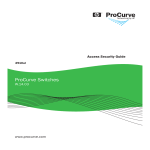
Figure 1 Diagram showing how to correctly hold, while moving, the DGS-6604
NOTE: Do not move the equipment by grasping the panel, power supply handle, or the
ventilation holes of the chassis as they are not designed to bear the weight of the entire
equipment. Attempting to move the Switch in this way may cause damage or cause you an
injury.
Electrical Safety
•
Please follow any applicable safety regulations and laws when performing electrical work. All electrical
work should be carried out by a qualified individual.
•
Before beginning any work with the switch carefully check for any potential dangers in the working area,
eg. a damp or wet floor, an ungrounded power supply, or an unreliable grounding of the power supply.
•
Locate the emergency power off switch in the room before installing or working on the switch.
•
If an electrical accident occurs, cut off the power supply to the Switch first.
x
DGS-6600 Layer 3 Chassis Ethernet Managed Switch Hardware Installation Guide
•
Avoid carrying out maintenance on the equipment alone when the Switch is powered on.
•
Before shutting down the power supply, check that it is safe to do so.
•
Do not place the Switch in a damp/wet location. Ensure that no liquid enters the chassis.
•
Ensure that all grounding conductors are connected both before, and after the line and neutral (AC)
conductors are connected.
•
Disconnect all power supply cords before servicing.
•
Connect the power cable to a circuit breaker rated not greater than 20A.
•
When installing multiple power supplies, connect each power supply to a different, independent overcurrent protection device, such as a circuit breaker. If a single power source fails, it will affect only the
power supply to which it is connected.
xi
DGS-6600 Layer 3 Chassis Ethernet Managed Switch Hardware Installation Guide
Grounding requirements
Proper grounding of the switch will help ensure stable and reliable operation of the DGS-6600 series switch. it is
important to verify that the grounding conditions during and after installation of the switch meet the grounding
requirements and grounds all devices properly.
All grounding conductors should be connected before the AC power is applied to the DGS-6600 series switch
installed AC power supplies.
The DGS-6604 series switch with AC power supplies must be grounded with a minimum of 0.823 mm2 (or
18AWG) of conductive grounding cable. This cable is connected between the Equipment Room Ground and the
DGS-6600 series Chassis Ground Terminal.
The DGS-6608 series switch with AC power supplies must be grounded with a minimum of 1.32 mm2
(or16AWG) of conductive grounding cable.
CAUTION: Indirectly or directly contacting the mains supply with a wet object can
cause a fatal danger.
CAUTION: Hazards, including electrical shocks and fires, can be caused by any
non-standard and inaccurate electrical operation. This may cause severe or fatal
damage to the human body or equipment.
Preventing Static Discharge Damage
While all precautions have been taken with the design of the DGS-6600 series switch to prevent damage from
static electricity, if the static electricity exceeds a certain limit, damage may be caused to the Switch's circuitry
and equipment.
Electrostatic induction may come from the following sources on the network that the DGS-6600 series switch is a
member of:
•
External electric fields produced by high-voltage cable supplies, lightning etc.
•
Internal building factors, such as the internal floor or the building structure.
The following factors must be paid attention to in order to prevent damage from static electricity: To prevent
damage from static electricity, please use the following guidelines:
1. Be sure to install an adequate ground for all electronic equipment.
2. Use appropriate dust prevention measures.
3. Maintain the required humidity in the operating environment.
4. Hold circuit boards by their edges. Do not touch any components on the printed circuit board (PCB).
5. Always wear an anti-static wrist strap when working near any electronic circuitry.
6. Do not allow clothing to touch circuit boards. An antistatic wrist strap will only prevent static electricity from
the human body, it will not reduce the static electricity build up on clothing.
xii
DGS-6600 Layer 3 Chassis Ethernet Managed Switch Hardware Installation Guide
Laser Safety
A number of the optical modules included in the DGS-6600 series switches are Class I laser products. Therefore,
when using these products pay careful attention to the following:
•
Ensure that any working fiber transceivers are either connected to a working optical fiber connection or
covered with a dust cap, to keep out of dust and avoid damaging your eyesight.
•
Never look into any optical port.
CAUTION: Never stare into any optical port under any circumstances, as this may
damage your eye sight.
xiii
DGS-6600 Layer 3 Chassis Ethernet Managed Switch Hardware Installation Guide
Chapter 1 Introduction
DGS-6600 Series Switch Description
DGS-6604 Product Specifications
DGS-6604 Product Appearance
DGS-6604 Hardware Composition
DGS-6604 Ventilation/Heat Dissipation System
DGS-6608 Product Specifications
DGS-6608 Hardware Composition
DGS-6608 Ventilation/Heat Dissipation System
DGS-6600 CPU & I/O Modules
DGS-6600 Series Switch Description
The D-Link's DGS-6600 series switch is a modular, chassis-based Ethernet backbone switch designed for
adaptability and scalability. Currently, the DGS-6600 series chassis is available in a 4-slot chassis (DGS-6604)
and 8 slot chassis (DGS-6608). The DGS-6600 Switch provides a management platform with a backplane switch
capacity of 576Gbps per Management Module. The chassis contains, one slot for the management module and
three slots for line card modules in the DGS-6604, and two slots for the management module with six slots for the
line card modules in the DGS-6608. All the supported modules are capable of being hot-swapped. The DGS6600 chassis provides a built-in power shelf that supports, depending DGS-6604 or DGS-6608 chassis type; up
to four or eight, redundant power modules. Multiple redundant power modules enable continuous operation in the
event of a power module failure.
DGS-6604 Product Specifications
Product Features
•
Powerful Expansion Capabilities
The DGS-6604 is capable of supporting strategic routing and IPv6. With support for multiple types of
line cards, the DGS-6600 allows users to customize their Switch configuration to meet their network
requirements.
•
Hot-Swappable Line Cards, Fan Tray, and Power Supplies
The DGS-6604 supports the hot-swapping of line cards, the fan tray, and power supplies to
minimize disruption to the network when a fault occurs.
•
Power Supply Redundancy
The DGS-6604 has a built-in power shelf that can host multiple power modules. If the DGS-6600 is
running in a non-PoE environment, the Switch can operate using only one power supply. in a worst
case scenario with three 48-port PoE line cards installed, all PSUs being inserted can meet the
power request.
•
Efficient Data Processing Design
The DGS-6604 implements complicated functions, such as switching, routing, ACL, and QoS via the
Switch hardware. Using the Switch hardware avoids the issues that can occur when implementing
complex functions within software.
Several functions are performed by the management module, including network management, route
management, and providing network services. The line card modules are capable of using their
hardware to independently implement functions like routing, switching, and multicast using their
hardware. The individual switch ports are capable of using their hardware to implement ACL and
QoS functions. These combined features greatly improve the equipment processing capability.
•
Physical Resilience
1
DGS-6600 Layer 3 Chassis Ethernet Managed Switch Hardware Installation Guide
The DGS-6604 includes several features that ensure physical resilience, including multiple
redundant power supplies and the capability of hot-swapping line cards or modules in the event of a
fault.
•
Secure Switch Management Methods
The DGS-6604 supports several features to prevent non-administrators from logging into the Switch
and potentially causing disruption to the network. These features include the Secure Shell (SSH)
encrypted login function and the option of restricting Telnet and web access to a specific group of
source IP addresses.
•
Support for 802.1X
The DGS-6604 supports 802.1X. 802.1X is a mechanism that is designed to only allow authorized
users, or other network devices, access to network resources by establishing criteria for each port
on the Switch that a user or network device must meet before allowing that port to forward or receive
frames.
•
Support for a Wide Range of Applications
The DGS-6604 supports a wide range of applications including QoS and multicast.
The QoS techniques supported by the Switch include Strict Priority Mode, Weighted Round Robin
(WRR), Deficit Round Robin (DRR), and Head of Line (HOL) blocking. These QoS techniques help
to provide bandwidth assurance for the various applications.
The multiple multicast support techniques supported by the Switch include IGMP snooping, IGMP,
PIM (SM,DM), and DVMRP. These multicast support techniques ensure that the minimum
bandwidth required for multicast applications is provided on the network.
•
Support for Equal-Cost Multipath Routing (ECMP)
When traditional routing techniques are used on a network that has multiple links that can reach the
same address, packets can only take one of the links to reach their destination, with all other links
being in standby or inactive. Another issue with traditional routing techniques is that the switching
between the various links can take some time in an environment that is using dynamic routing.
Compared to traditional routing techniques, ECMP is a great improvement as it can use multiple
links at the same time in a resilient network environment. As well as increasing transmission
bandwidth, ECMP also backs up the data transmission on the link that has failed without causing
any delays or packet loss.
•
STP and VRRP Support
The DGS-6604 supports both the Spanning-Tree Protocol (STP) and Virtual Router Redundancy
Protocol (VRRP). The Spanning-Tree Protocol (STP) versions supported by the Switch include
Spanning-Tree Protocol (IEEE 802.1D), Rapid Spanning-Tree Protocol (IEEE 802.1w), and Multiple
Spanning-Tree Protocol (IEEE 802.1s).
2
DGS-6600 Layer 3 Chassis Ethernet Managed Switch Hardware Installation Guide
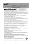
DGS-6604 Product Appearance
Figure 1-1 DGS-6604 Product Appearance
Number
Item Name
Description
1
Power Layer
The built-in power shelf can host up to four power modules.
2
Module Layer
The module layer offers 4 module slots.
3
Air Outlet
The air outlet is located on the right side of the Switch.
4
Fan Tray
The fan tray is installed in the slot on the right side of the Switch.
The fan tray is the Switch’s main heat dissipation unit.
Table 1-1 DGS-6604 Product Appearance Descriptions
3
DGS-6600 Layer 3 Chassis Ethernet Managed Switch Hardware Installation Guide
DGS-6604 Hardware Composition
The DGS-6604 hardware consists of a chassis, management card, line cards, power system and a fan system.
Chassis
The DGS-6604 uses a standard 19-inch chassis, which has a height of 280mm, a width of 484mm, and a depth
of 470mm. The chassis consists of the system module layer, fan layer, and power layer.
The layer that handles system modules consists of a module plug-in frame, which is used for connecting the
various DGS-6604 modules.
The built-in power shelf is located at the top of the chassis.
The fan tray is located on the right-hand side of the chassis. The fan tray consists of eight fans. The dimension of
each fan is 80x80x20mm.
Module Plug-in Frame
The module plug-in frame of the DGS-6604 consists of the module slots and the backplane.
The DGS-6604 supports four module slots. The slot at the top of the Switch can only be used for the control
management module. The other three slots can be used to connect to various line cards. All the modules
supported by the DGS-6604 are of the same height, width and depth. The dimensions of each module are a
height of 42mm, a width of 388mm, and a depth of 422mm. The modules of the DGS-6604 are inserted into the
Switch horizontally. The backplane of the DGS-6604 is used to interconnect the control management card and
the line cards that have been installed in the Switch.
The main functions of the DGS-6604 backplane are listed below:
•
Providing a mechanism for transmitting various signals between the modules and providing channels
for high-speed communication.
•
Acting as a passive backplane.
•
Automatically identifying the type of line card that has been installed in each slot.
•
Managing the load distribution among the installed power supplies.
When the slots of the DGS-6604 are fully populated, the modules of the DGS-6604 will have the following layout:
•
One control management module.
•
Three line card modules to meet the network requirements.
The slot number used for the Control Management module is 1. Slots 2, 3, and 4 are used for line card modules.
4
DGS-6600 Layer 3 Chassis Ethernet Managed Switch Hardware Installation Guide
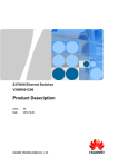
DGS-6604 Ventilation/Heat Dissipation System
The DGS-6604 operates at a temperature of 0-50ºC. The hardware of the DGS-6604 has been thermally
designed so the surface temperature of the components does not exceed the allowed ambient temperature of
50ºC without affecting the reliability, security, and repairability of the Switch. The thermal design of the DGS-6604
hardware uses fans to induct air in a forced convection so that the equipment operates normally in the specified
environment. The diagram below shows the ventilation/heat dissipation system that has been implemented on
the DGS-6604.
Figure 1-2 DGS-6604 Ventilation/Heat Dissipation System
NOTE: The air flow direction for the DGS-6604 is from the left to the right.
DGS-6608 Product Specifications
Product Features
•
Powerful Expansion Capabilities
The DGS-6608 is capable of supporting strategic routing and IPv6. With support for multiple types of
line cards, the DGS-6608 allows users to customize their Switch configuration to meet their network
requirements.
•
Hot-Swappable Line Cards, Fan Tray, and Power Supplies
The DGS-6608 supports the hot-swapping of line cards, the fan tray, and power supplies to
minimize disruption to the network when a fault occurs.
•
Power Supply Redundancy
The DGS-6608 has two built-in power shelves that can host up to eight power modules. If the DGS6608 is running in a non-PoE environment, the Switch can operate using only two power supply. in a
worst case scenario with six 48-port PoE line cards installed, all 8 x PSUs inserting can meet the
power request. In this case, the system does not support RPS.
5
DGS-6600 Layer 3 Chassis Ethernet Managed Switch Hardware Installation Guide
•
Efficient Data Processing Design
The DGS-6608 implements complicated functions, such as switching, routing, ACL, and QoS via the
Switch hardware. Using the Switch hardware avoids the issues that can occur when implementing
complex functions within software.
Several functions are performed by the management module, including network management, route
management, and providing network services. The line card modules are capable of using their
hardware to independently implement functions like routing, switching, and multicast using their
hardware. The individual switch ports are capable of using their hardware to implement ACL and
QoS functions. These combined features greatly improve the equipment processing capability.
•
Physical Resilience
The DGS-6608 includes several features that ensure physical resilience, including multiple
redundant power supplies and the capability of hot-swapping line cards or modules in the event of a
fault.
•
Secure Switch Management Methods
The DGS-6608 supports several features to prevent non-administrators from logging into the Switch
and potentially causing disruption to the network. These features include the Secure Shell (SSH)
encrypted login function and the option of restricting Telnet and web access to a specific group of
source IP addresses.
•
Support for 802.1X
The DGS-6608 supports 802.1X. 802.1X is a mechanism that is designed to only allow authorized
users, or other network devices, access to network resources by establishing criteria for each port
on the Switch that a user or network device must meet before allowing that port to forward or receive
frames.
•
Support for a Wide Range of Applications
The DGS-6608 supports a wide range of applications including QoS and multicast.
The QoS techniques supported by the Switch include Strict Priority Mode, Weighted Round Robin
(WRR), Deficit Round Robin (DRR), and Head of Line (HOL) blocking. These QoS techniques help
to provide bandwidth assurance for the various applications.
The multiple multicast support techniques supported by the Switch include IGMP snooping, IGMP,
PIM (SM,DM), and DVMRP. These multicast support techniques ensure that the minimum
bandwidth required for multicast applications is provided on the network.
•
Support for Equal-Cost Multipath Routing (ECMP)
When traditional routing techniques are used on a network that has multiple links that can reach the
same address, packets can only take one of the links to reach their destination, with all other links
being in standby or inactive. Another issue with traditional routing techniques is that the switching
between the various links can take some time in an environment that is using dynamic routing.
Compared to traditional routing techniques, ECMP is a great improvement as it can use multiple
links at the same time in a resilient network environment. As well as increasing transmission
bandwidth, ECMP also backs up the data transmission on the link that has failed without causing
any delays or packet loss.
•
STP and VRRP Support
The DGS-6608 supports both the Spanning-Tree Protocol (STP) and Virtual Router Redundancy
Protocol (VRRP). The Spanning-Tree Protocol (STP) versions supported by the Switch include
Spanning-Tree Protocol (IEEE 802.1D), Rapid Spanning-Tree Protocol (IEEE 802.1w), and Multiple
Spanning-Tree Protocol (IEEE 802.1s).
•
High Port Density
The DGS-6608 supports up to 288 gigabit Ethernet ports or 96 ten gigabit Ethernet ports.
6
DGS-6600 Layer 3 Chassis Ethernet Managed Switch Hardware Installation Guide
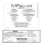
DGS-6608 Product Appearance
Figure 1-3 DGS-6608 Product Appearance
Number
Item Name
Description
1
Power Layer
The built-in power shelf can host up to eight power modules.
2
Module Layer
The module layer offers 8 module slots.
3
Air Outlet
The air outlet is located on the right side of the Switch.
4
Fan Tray
The fan tray is installed in the slot on the right side of the Switch.
The fan tray is the Switch’s main heat dissipation unit.
Table 1-2 DGS-6608 Product Appearance Descriptions
7
DGS-6600 Layer 3 Chassis Ethernet Managed Switch Hardware Installation Guide
DGS-6608 Hardware Composition
The DGS-6608 hardware consists of a chassis, management card, line cards, power system and a fan system.
Chassis
The DGS-6608 uses a standard 19-inch chassis. The chassis consists of the system module layer, fan layer, and
power layer.
The layer that handles system modules consists of a module plug-in frame, which is used for connecting the
various DGS-6608 modules.
The built-in power shelf is located at the top of the chassis.
The fan tray is located on the right-hand side of the chassis. The fan tray consists of Sixteen fans. The dimension
of each fan is 80x80x20mm.
Module Plug-in Frame
The module plug-in frame of the DGS-6608 consists of the module slots and the backplane.
The DGS-6608 supports eight module slots. The slots 4 and 5 of the Switch can only be used for the control
management module. The other six slots can be used to connect to various line cards. All the modules supported
by the DGS-6608 are of the same height, width and depth. The dimensions of each module are a height of
42mm, a width of 388mm, and a depth of 422mm. The modules of the DGS-6608 are inserted into the Switch
horizontally. The backplane of the DGS-6608 is used to interconnect the control management card and the line
cards that have been installed in the Switch.
The main functions of the DGS-6608 backplane are listed below:
•
Providing a mechanism for transmitting various signals between the modules and providing channels
for high-speed communication.
•
Acting as a passive backplane.
•
Automatically identifying the type of line card that has been installed in each slot.
•
Managing the load distribution among the installed power supplies.
When the slots of the DGS-6608 are fully populated, the modules of the DGS-6608 will have the following layout:
•
Two control management module.
•
Six line card modules to meet the network requirements.
The slot number used for the Control Management module is 4 and 5. Slots 1-3 to 6-8 are used for line card
modules.
8
DGS-6600 Layer 3 Chassis Ethernet Managed Switch Hardware Installation Guide
DGS-6608 Ventilation/Heat Dissipation System
The DGS-6608 operates at a temperature of 0-50ºC. The hardware of the DGS-6608 has been thermally
designed so the surface temperature of the components does not exceed the allowed ambient temperature of
50ºC without affecting the reliability, security, and repairability of the Switch. The thermal design of the DGS-6608
hardware uses fans to induct air in a forced convection so that the equipment operates normally in the specified
environment. The diagram below shows the ventilation/heat dissipation system that has been implemented on
the DGS-6608.
Figure 1-4 DGS-6608 Ventilation/Heat Dissipation System
NOTE: The air flow direction for the DGS-6608 is from the left to the right.
9
DGS-6600 Layer 3 Chassis Ethernet Managed Switch Hardware Installation Guide
DGS-6600 CPU & I/O Modules
The DGS-6604/6608 supports the modules described below:
DGS-6600-CM: The DGS-6600-CM is a CPU module for the DGS-6604 Series. The CPU module is used to
manage the entire system, including layer 2 and layer 3 processes, controlling and managing user access,
managing routes, and maintenance on the network and operations.
DGS-6600-CM-II: The DGS-6600-CM-II is a CPU module for the DGS-6604/6608, the DGS-6608 is able to
support 2 x CM.
DGS-6600-24SC2XS: This module includes 12 SFP ports, 12 combo ports (10/100/1000Base-T/SFP Module) and 2
SFP+ ports.
DGS-6600-16XS-D: This module includes 16 10G SFP+ ports.
DGS-6600-48P: This module includes 48 10/100/1000 Base -T ports and PoE.
DGS-6600-48S: This module includes 48 SFP interfaces.
DGS-6600-48T: This module includes 48 10/100/1000 Base-T ports.
DGS-660048TS: This module includes 24 10/100/1000 Base-T ports and 24 SFP interfaces.
DGS-6600-8XG: This module includes 8 10G XFP interfaces and is only supported by the DGS-6604.
10
DGS-6600 Layer 3 Chassis Ethernet Managed Switch Hardware Installation Guide
DGS-6600-CM Module
The basic appearance of the DGS-6600-CM management module is shown in Figure 1-5. The DGS-6600-CM
management module is designed to manage all features of the DGS-6604 model including: system switching,
controlling user access, managing user access, controlling the system status, managing routing, controlling
maintenance on the network and controlling network operations. The DGS-6600-CM management module needs
to be inserted in slot 1 of the chassis.
NOTE: The DGS-6604 needs one DGS-6600-CM management module to operate.
Figure 1-5 Basic Appearance of DGS-6600-CM
Interface
UART Console Interface
The DGS-6600-CM front panel provides two types of UART Console Interface. The first console interface is an
RS-232 connector and the second console interface is a USB connector. These two interfaces are mutually
exclusive; the USB interface has a higher priority. If the Switch is being managed via the RS-232 console
connection and a USB connection is established, the CLI engine will use the USB connection and automatically
disconnect the user that is connected to the Switch via the RS-232 console connection.
Out-of-Band Management Port
The DGS-6600-CM module features an out-of-band Management port. The management port uses an RJ-45
connected so it can be easily connected to a notebook computer using a standard Ethernet cable. Connect to the
port for out-of-band management using a web browser or Telnet command prompt interface. The Management
port is enabled by default, so it can be used for the first time that you connect to the Switch.
To use the management port, use an Ethernet cable to connect the port to the Ethernet interface of a computer
used for Switch management. The default IP address of the management port is 10.90.90.90 with a subnet mask
of 255.0.0.0, make sure the computer used for Switch management has a non-conflicting IP address in the
10.0.0.0/8 subnet.
11
DGS-6600 Layer 3 Chassis Ethernet Managed Switch Hardware Installation Guide
LEDs
The DGS-6600-CM uses different colored LEDs to indicate different systems status, as described in Table 1-3.
LED Indicator
Power
Color and Status
Description
Solid Green
This LED will light solid green when the Switch is powered on.
Off
This LED will remain off when the Switch is powered off.
Solid Green
This LED will light solid green when the Switch is operating
normally.
Solid Red
This LED will light solid red when the Switch has failed.
Blinking Green
This LED will blink green while the Switch is booting up or
shutting down.
Off
This LED will remain off when the Switch is shut down.
CPU Utilization
Solid Green
These LEDs are used to indicate the percentage of CPU
utilization. The valid values are from 30% to 100%.
Master
Solid Green
This LED will light green when the CPU module is acting as the
master management card.
Off
This LED will remain off when the CPU module is acting as the
backup management card.
Solid Green
This LED will light green when a user has logged into the
Switch via the USB console port.
Off
This LED will remain off when the USB console port is not in
use.
Solid Green
This LED will light green when a user has logged into the
Switch via the RS-232 console port.
Off
This LED will remain off when the RS-232 console port is not in
use.
Blinking Green
This LED will blink green when the CF card is being read or
written to.
System
USB
RS-232
Compact Flash
Table 1-3 DGS-6600-CM LED Behavior
12
DGS-6600 Layer 3 Chassis Ethernet Managed Switch Hardware Installation Guide
Technical Specifications
Item
Description
Standard
Compliance
Management port supports IEEE802.3, IEEE802.3u, IEEE802.3ab Half/Full-duplex support
Management
Mode
CLI
Telnet
Web-based
Port Type
1x Female DCE RS-232 DB-9 console port
1x Female USB series type B console port
1x RJ-45 management port
LED
Power
System
CPU Utilization
Master
USB
RS-232
Compact Flash
Hot Swap
Ability
Not-supported
Power
Consumption
53.856 Watts
EMC
EMC (Class A):
FCC Part 15, CSA C108.8, 89/336/EEC, EN 55022, EN 61000-3-2, EN 61000-3-3, EN
61000-4-2, EN 61000-4-3, EN 61000-4-4, EN 61000-4-5, EN 61000-4-6, EN 61000-4-11, EN
55024, AS/NZS 3548, VCCI V-3.
Safety
Regulation
UL 1950, CSA C22.2 No. 950, 73/23/EEC, EN 60825, EN 60950, IEC 950
MTBF
263581 Hours
Heat
Dissipation
183.6 BTU/Hour
Operating
Temperature
0~50ºC
Storage
Temperature
-40~70ºC
Operating
Humidity
10% - 90% RH non-condensed
Weight
3.605 Kilograms
Dimensions
height - 42mm, width - 388mm , depth - 422mm
Table 1-4 DGS-6600-CM Technical Specifications
13
DGS-6600 Layer 3 Chassis Ethernet Managed Switch Hardware Installation Guide
DGS-6600-CM-II management module:
The basic appearance of the DGS-6600-CM-II management module is shown in Figure 1-6. The DGS-6600-CMII management module is designed to manage all features of the DGS-6608 Switch including: system switching,
controlling user access, managing user access, controlling the system status, managing routing, controlling
maintenance on the network and controlling network operations. The DGS-6600-CM-II management module
needs to be inserted in slot 1 in DGS-6604 and slot 4 and 5 in the DGS-6608
NOTE: The DGS-6608 needs at least one DGS-6600-CM-II management modules to operate.
Figure 1-6 Basic Appearance of DGS-6600-CM-II
Interface
UART Console Interface
The DGS-6600-CM-II front panel provides two types of UART Console Interface. The first console interface is an
RS-232 connector and the second console interface is a USB connector. These two interfaces are mutually
exclusive; the USB interface has a higher priority. If the Switch is being managed via the RS-232 console
connection and a USB connection is established, the CLI engine will use the USB connection and automatically
disconnect the user that is connected to the Switch via the RS-232 console connection.
Out-of-Band Management Port
The DGS-6600-CM-II module features an out-of-band Management port. The management port uses an RJ-45
connected so it can be easily connected to a notebook computer using a standard Ethernet cable. Connect to the
port for out-of-band management using a web browser or Telnet command prompt interface. The Management
port is enabled by default, so it can be used for the first time that you connect to the Switch.
To use the management port, use an Ethernet cable to connect the port to the Ethernet interface of a computer
used for Switch management. The default IP address of the management port is 10.90.90.90 with a subnet mask
of 255.0.0.0, make sure the computer used for Switch management has a non-conflicting IP address in the
10.0.0.0/8 subnet.
14
DGS-6600 Layer 3 Chassis Ethernet Managed Switch Hardware Installation Guide
LEDs
The DGS-6600-CM-II uses different colored LEDs to indicate different systems status, as described in Table 1-5.
LED Indicator
Power
Color and Status
Description
Solid Green
This LED will light solid green when the Switch is powered on.
Off
This LED will remain off when the Switch is powered off.
Solid Green
This LED will light solid green when the Switch is operating
normally.
Solid Red
This LED will light solid red when the Switch has failed.
Blinking Green
This LED will blink green while the Switch is booting up or
shutting down.
Off
This LED will remain off when the Switch is shut down.
CPU Utilization
Solid Green
These LEDs are used to indicate the percentage of CPU
utilization. The valid values are from 30% to 100%.
Master
Solid Green
This LED will light green when the CPU module is acting as the
master management card.
Off
This LED will remain off when the CPU module is acting as the
backup management card.
Solid Green
This LED will light green when a user has logged into the
Switch via the USB console port.
Off
This LED will remain off when the USB console port is not in
use.
Solid Green
This LED will light green when a user has logged into the
Switch via the RS-232 console port.
Off
This LED will remain off when the RS-232 console port is not in
use.
Blinking Green
This LED will blink green when the CF card is being read or
written to.
System
USB
RS-232
Compact Flash
Table 1-5 DGS-6600-CM-II LED Behavior
15
DGS-6600 Layer 3 Chassis Ethernet Managed Switch Hardware Installation Guide
Technical Specifications
Item
Description
Standard
Compliance
Management port supports IEEE802.3, IEEE802.3u, IEEE802.3ab Half/Full-duplex support
Management
Mode
CLI
Telnet
Web-based
Port Type
1x Female DCE RS-232 DB-9 console port
1x Female USB series type B console port
1x RJ-45 management port
LED
Power
System
CPU Utilization
Master
USB
RS-232
Compact Flash
Hot Swap
Ability
Supported
Power
Consumption
54.86 Watts
EMC
EMC (Class A):
FCC Part 15, CSA C108.8, 89/336/EEC, EN 55022, EN 61000-3-2, EN 61000-3-3, EN
61000-4-2, EN 61000-4-3, EN 61000-4-4, EN 61000-4-5, EN 61000-4-6, EN 61000-4-11, EN
55024, AS/NZS 3548, VCCI V-3.
Safety
Regulation
UL 1950, CSA C22.2 No. 950, 73/23/EEC, EN 60825, EN 60950, IEC 950
MTBF
317755 Hours
Heat
Dissipation
187.19 BTU/Hour
Operating
Temperature
0~50ºC
Storage
Temperature
-40~70ºC
Operating
Humidity
10% - 90% RH non-condensed
Weight
3.76 Kilograms
Dimensions
height - 42mm, width - 388mm, depth - 422mm
Table 1-6 DGS-6600-CM-II Technical Specifications
16
DGS-6600 Layer 3 Chassis Ethernet Managed Switch Hardware Installation Guide
DGS-6600-24SC2XS Module
The basic appearance of the DGS-6600-24SC2XS module is shown in Figure 1-7. The DGS-6600-24SC2XS is a
line card module of the DGS-6604, which provides 12 SFP ports, 12 combo ports (10/100/1000Base-T/SFP Module)
and 2 SFP+ ports.
Figure 1-7 Basic Appearance of DGS-6600-24SC2XS
Interface
The DGS-6600-24SC2XS features 12 SFP ports, 12 combo ports (10/100/1000Base-T/SFP Module) and 2 SFP+
ports, please note that the DGS-6600-24SC2XS last two SFP+ ports do not support DEM-310GT/311GT/312GT2/
314GT/315GT/330T/R/331T/R/210/211/220/T/R or DGS-712 transceiver.
LEDs
The DGS-6600-24SC2XS uses different colored LEDs to indicate different systems status, described in Table 17.
LED
Indicator
Power
System
Link/Act/
Speed Mode
Color and Status
Description
Solid Green
This LED will light solid green when the Switch is powered on.
Off
This LED will remain off when the Switch is powered off.
Solid Green
This LED will light solid green when the Switch is operating
normally.
Solid Red
This LED will light solid red when the Switch has failed.
Blinking Green
This LED will blink green while the Switch is booting up or
shutting down.
Off
This LED will remain off when the Switch is shut down.
Solid Green
This LED will light solid green when there is a secure
connection (or link) to a device. (Either 1000 Mbps or 10 Gbps,
depending on if it is a 10/100/1000 Mbps port, SFP port or a
10G port.)
Blinking Green
This LED will blink green when there is activity occurring on a
port that is operating. (Either 1000 Mbps or 10 Gbps, depending
on if it is a 10/100/1000 Mbps port, SFP port or a 10G port.)
Solid Amber
When there is a secure connection or link at any of the ports.
(Either 10/100 Mbps or 100 Mbps, depending on if it is a 10/
100/1000 Mbps port or an SFP port.)
Blinking Amber
When there is a reception of transmission. (Either 10/100 Mbps
or 100 Mbps, depending on if it is a 10/100/1000 Mbps port or
an SFP port.)
Off
This LED will remain off when there is no link on the port.
Table 1-7 DGS-6600-24SC2XS LED Behavior
17
DGS-6600 Layer 3 Chassis Ethernet Managed Switch Hardware Installation Guide
Technical Specifications
Item
Compliance
Standard
Compliance
IEEE 802.3
IEEE 802.3ab
IEEE 802.3ae
IEEE 802.3aq
IEEE 802.3u
IEEE 802.3z
Full-duplex support/Half-duplex support (IEEE 802.3x Flow Control support for Full-Duplex
mode)
SFF-8431 compliant transceiver support
Port Type
12 SFP ports, 12 combo ports (10/100/1000Base-T/SFP Module) and 2 SFP+ ports.
LED
Power
System
Hot Swap
Ability
Supported
Power
Consumption
105.5 Watts
EMC
EMC (Class A):
FCC Part 15, CSA C108.8, 89/336/EEC, EN 55022, EN 61000-3-2, EN 61000-3-3, EN
61000-4-2, EN 61000-4-3, EN 61000-4-4, EN 61000-4-5, EN 61000-4-6, EN 61000-4-11, EN
55024, AS/NZS 3548, VCCI V-3.
Safety
Regulation
UL 1950, CSA C22.2 No. 950, 73/23/EEC, EN 60825, EN 60950, IEC 950
MTBF
349982.9658 Hours
Heat
Dissipation
379.8 BTU/Hour
Weight
3.328 Kilograms
Table 1-8 DGS-6600-24SC2XS Technical Specifications
18
DGS-6600 Layer 3 Chassis Ethernet Managed Switch Hardware Installation Guide
DGS-6600-16XS-D
The basic appearance of the DGS-6600-16XS-D module is shown in Figure 1-8. The DGS-6600-16XS-D is a line
card module of the DGS-6604/6608, which provides 16x 10G SFP+ ports.
Figure 1-8 Basic Appearance of the DGS-6600-16XS-D
Interface
The DGS-6600-16XS-D features 16x 10G SFP+ ports.
LEDs
The DGS-6600-16XS-D uses different colored LEDs to indicate different systems status, described in Table 1-9.
LED
Indicator
Power
System
Link/Act/
Speed Mode
Color and Status
Description
Solid Green
This LED will light solid green when the Switch is powered on.
Off
This LED will remain off when the Switch is powered off.
Solid Green
This LED will light solid green when the Switch is operating
normally.
Solid Red
This LED will light solid red when the Switch has failed.
Blinking Green
This LED will blink green while the Switch is booting up or
shutting down.
Off
This LED will remain off when the Switch is shut down.
Solid Green
This LED will light solid green when there is a secure
connection (or link), with a link speed of 10G.
Blinking Green
This LED will blink green when there is activity occurring on a
port that is operating.
Solid Amber
When there is a secure connection or link at any of the ports
with a link speed of 1G.
Blinking Amber
When there is a reception of transmission.
Off
This LED will remain off when there is no link on the port.
Table 1-9 DGS-6600-16XS-D LED Behavior
19
DGS-6600 Layer 3 Chassis Ethernet Managed Switch Hardware Installation Guide
Technical Specifications
Item
Compliance
Standard
Compliance
IEEE 802.3
IEEE 802.3ab
IEEE 802.3ae
IEEE 802.3aq
IEEE 802.3u
IEEE 802.3z
Full-duplex support/Half-duplex support (IEEE 802.3x Flow Control support for Full-Duplex
mode)
SFF-8431 compliant transceiver support
Port Type
16 x 10G SFP+ ports.
LED
Power
System
Hot Swap
Ability
Supported
Power
Consumption
179.84W
EMC
EMC (Class A):
FCC Part 15, CSA C108.8, 89/336/EEC, EN 55022, EN 61000-3-2, EN 61000-3-3, EN
61000-4-2, EN 61000-4-3, EN 61000-4-4, EN 61000-4-5, EN 61000-4-6, EN 61000-4-11, EN
55024, AS/NZS 3548, VCCI V-3.
Safety
Regulation
UL 1950, CSA C22.2 No. 950, 73/23/EEC, EN 60825, EN 60950, IEC 950
Heat
Dissipation
613.25BTU/hr
Weight
3.328 Kilograms
Table 1-10 DGS-6600-16XS-D Technical Specifications
20
DGS-6600 Layer 3 Chassis Ethernet Managed Switch Hardware Installation Guide
DGS-6600-48P Module
The basic appearance of the DGS-6600-48P module is shown in Figure 1-9. The DGS-6600-48P is a line card
module of the DGS-6604/6608, which features 48x10/100/1000 RJ-45 and POE ports.
Figure 1-9 Basic Appearance of DGS-6600-48P
21
DGS-6600 Layer 3 Chassis Ethernet Managed Switch Hardware Installation Guide
LEDs
The DGS-6600-48P uses different colored LEDs to indicate different systems status, as described in Table 1-11.
LED
Indicator
Power
System
Link/Act/
Speed Mode
PoE
Color and Status
Description
Solid Green
This LED will light solid green when the Switch is powered on.
Off
This LED will remain off when the Switch is powered off.
Solid Green
This LED will light solid green when the Switch is operating
normally.
Solid Red
This LED will light solid red when the Switch has failed.
Blinking Green
This LED will blink green while the Switch is booting up or
shutting down.
Off
This LED will remain off when the Switch is shut down.
Solid Green
This LED will light solid green when there is a secure
connection (or link) to a device that is operating at 1000Mbps.
Blinking Green
This LED will blink green when there is activity occurring on a
port that is operating at 1000Mbps.
Solid Amber
This LED will light solid amber when there is a secure
connection (or link) to a device that is operating at 10/100Mbps.
Blinking Amber
This LED will blink amber when there is activity occuring on a
port that is operating at 10/100Mbps.
Off
This LED will remain off when there is no link on the port.
Solid Green
Solid Green: port LEDs indicate PSE supply power or not.
Off
Off: port LEDs indicate ethernet link status
Table 1-11 DGS-6600-48P LED Behaviors
22
DGS-6600 Layer 3 Chassis Ethernet Managed Switch Hardware Installation Guide
Technical Specifications
Item
Compliance
Standard
Compliance
IEEE 802.3, IEEE 802.3u, IEEE 802.3ab, IEEE 802.3af, Half/full-duplex support
Port Type
48x 10/100/1000 Mbps PoE ports
LED
Power
System
PoE
Hot Swap
Ability
Supported
Power
Consumption
873 Watts
EMC
EMC (Class A):
FCC Part 15, CSA C108.8, 89/336/EEC, EN 55022, EN 61000-3-2, EN 61000-3-3, EN
61000-4-2, EN 61000-4-3, EN 61000-4-4, EN 61000-4-5, EN 61000-4-6, EN 61000-4-11, EN
55024, AS/NZS 3548, VCCI V-3.
Safety
Regulation
UL 1950, CSA C22.2 No. 950, 73/23/EEC, EN 60825, EN 60950, IEC 950
MTBF
160609 hrs
Heat
Dissipation
3037 BTU/hr
Weight
3.74 KG
Table 1-12 DGS-6600-48P Technical Specifications
23
DGS-6600 Layer 3 Chassis Ethernet Managed Switch Hardware Installation Guide
DGS-6600-48S Module
The basic appearance of the DGS-6600-48S module is shown in Figure 1-10. The DGS-6600-48S is a line card
module of the DGS-6604/6608, which provides 48x SFP modules.
Figure 1-10 Basic Appearance of DGS-6600-48S
Interface
The DGS-6600-48S features 48x SFP modules.
LEDs
The DGS-6600-48S uses different colored LEDs to indicate different systems status, as described in Table 1-13.
LED
Indicator
Power
System
Link/Act/
Speed Mode
Color and Status
Description
Solid Green
This LED will light solid green when the Switch is powered on.
Off
This LED will remain off when the Switch is powered off.
Solid Green
This LED will light solid green when the Switch is operating
normally.
Solid Red
This LED will light solid red when the Switch has failed.
Blinking Green
This LED will blink green while the Switch is booting up or
shutting down.
Off
This LED will remain off when the Switch is shut down.
Solid Green
This LED will light solid green when there is a secure
connection (or link) to a device that is operating at 1000Mbps.
Blinking Green
This LED will blink green when there is activity occurring on a
port that is operating at 1000Mbps.
Solid Amber
This LED will light solid amber when there is a secure
connection (or link) to a device that is operating at 100Mbps.
Blinking Amber
This LED will blink amber when there is activity occurring on a
port that is operating at 100Mbps.
Off
This LED will remain off when there is no link on the port.
Table 1-13 DGS-6600-48S LED Behavior
24
DGS-6600 Layer 3 Chassis Ethernet Managed Switch Hardware Installation Guide
Technical Specifications
Item
Compliance
Standard
Compliance
IEEE 802.3z
Full-duplex support
Port Type
48x SFP modules
LED
Power
System
Hot Swap
Ability
Supported
Power
Consumption
118.6 Watts
EMC
EMC (Class A):
FCC Part 15, CSA C108.8, 89/336/EEC, EN 55022, EN 61000-3-2, EN 61000-3-3, EN
61000-4-2, EN 61000-4-3, EN 61000-4-4, EN 61000-4-5, EN 61000-4-6, EN 61000-4-11, EN
55024, AS/NZS 3548, VCCI V-3.
Safety
Regulation
UL 1950, CSA C22.2 No. 950, 73/23/EEC, EN 60825, EN 60950, IEC 950
MTBF
318790 Hours
Heat
Dissipation
404.6 BTU/Hour
Weight
3.37 Kilograms
Table 1-14 DGS-6600-48S Technical Specifications
25
DGS-6600 Layer 3 Chassis Ethernet Managed Switch Hardware Installation Guide
DGS-6600-48T Module
The basic appearance of the DGS-6600-48T module is shown in Figure 1-11. The DGS-6600-48T is a line card
module of the DGS-6604/6608, which provides 48x10/100/1000 Base-T ports.
Figure 1-11 Basic Appearance of DGS-6600-48T
Interface
The DGS-6600-48T features 48x10/100/1000 RJ-45 ports.
LEDs
The DGS-6600-48T uses different colored LEDs to indicate different systems status, as described in Table 1-15.
LED
Indicator
Power
System
Link/Act/
Speed Mode
Color and Status
Description
Solid Green
This LED will light solid green when the Switch is powered on.
Off
This LED will remain off when the Switch is powered off.
Solid Green
This LED will light solid green when the Switch is operating
normally.
Solid Red
This LED will light solid red when the Switch has failed.
Blinking Green
This LED will blink green while the Switch is booting up or
shutting down.
Off
This LED will remain off when the Switch is shut down.
Solid Green
This LED will light solid green when there is a secure
connection (or link) to a device that is operating at 1000Mbps.
Blinking Green
This LED will blink green when there is activity occurring on a
port that is operating at 1000Mbps.
Solid Amber
This LED will light solid amber when there is a secure
connection (or link) to a device that is operating at 10/100Mbps.
Blinking Amber
This LED will blink green when there is activity occurring on a
port that is operating at 10/100Mbps.
Off
This LED will remain off when there is no link on the port.
Table 1-15 DGS-6600-48T LED Behavior
26
DGS-6600 Layer 3 Chassis Ethernet Managed Switch Hardware Installation Guide
Technical Specifications
Item
Compliance
Standard
Compliance
IEEE 802.3, IEEE 802.3u, IEEE 802.3ab
Half/Full-duplex Support
Port Type
48x 10/100/1000 Mbps RJ-45 ports
LED
Power
System
Hot Swap
Ability
Supported
Power
Consumption
109.8 Watts
EMC
EMC (Class A):
FCC Part 15, CSA C108.8, 89/336/EEC, EN 55022, EN 61000-3-2, EN 61000-3-3, EN
61000-4-2, EN 61000-4-3, EN 61000-4-4, EN 61000-4-5, EN 61000-4-6, EN 61000-4-11, EN
55024, AS/NZS 3548, VCCI V-3.
Safety
Regulation
UL 1950, CSA C22.2 No. 950, 73/23/EEC, EN 60825, EN 60950, IEC 950
MTBF
249309 Hours
Heat
Dissipation
374.4 BTU/Hour
Weight
3.51 Kilograms
Table 1-16 DGS-6600-48T Technical Specifications
27
DGS-6600 Layer 3 Chassis Ethernet Managed Switch Hardware Installation Guide
DGS-6600-48TS Module
The basic appearance of the DGS-6600-48TS module is in Figure 1-12. The DGS-6600-48TS is a line card
module of the DGS-6604/6608, which provides 24x 10/100/1000 Base-T ports and 24x SFP module ports.
Figure 1-12 Basic Appearance of DGS-6600-48TS
Interface
The DGS-6600-48TS provides 24x 10/100/1000 Base-T ports and 24x SFP module ports.
28
DGS-6600 Layer 3 Chassis Ethernet Managed Switch Hardware Installation Guide
LEDs
The DGS-6600-48TS uses different colored LEDs to indicate different systems status, as described in Table 117.
LED
Indicator
Power
System
10/100/
1000Mbps
Link/Act/
Speed Mode
SFP Module
Link/Act/
Speed Mode
Color and Status
Description
Solid Green
This LED will light solid green when the Switch is powered on.
Off
This LED will remain off when the Switch is powered off.
Solid Green
This LED will light solid green when the Switch is operating
normally.
Solid Red
This LED will light solid red when the Switch has failed.
Blinking Green
This LED will blink green while the Switch is booting up or
shutting down.
Off
This LED will remain off when the Switch is shut down.
Solid Green
This LED will light solid green when there is a secure
connection (or link) to a device that is operating at 1000Mbps.
Blinking Green
This LED will blink green when there is activity occurring on a
port that is operating at 1000Mbps.
Solid Amber
This LED will light solid amber when there is a secure
connection (or link) to a device that is operating at 10/100Mbps.
Blinking Amber
This LED will blink amber when there is activity occurring on a
port that is operating at 10/100Mbps.
Off
This LED will remain off when there is no link on the port.
Solid Green
This LED will light solid green when there is a secure
connection (or link) to a device that is operating at 1000Mbps.
Blinking Green
This LED will blink green when there is activity occurring on a
port that is operating at 1000Mbps.
Solid Amber
This LED will light solid amber when there is a secure
connection (or link) to a device that is operating at 100Mbps.
Blinking Amber
This LED will blink amber when there is activity occurring on a
port that is operating at 100Mbps.
Off
This LED will remain off when there is no link on the port.
Table 1-17 DGS-6600-48TS LED Behaviors
29
DGS-6600 Layer 3 Chassis Ethernet Managed Switch Hardware Installation Guide
Technical Specifications
Item
Compliance
Standard
Compliance
IEEE: 802.3, 802.3u, 802.3ab, 802.3z, 802.3x flow control support for full-duplex mode
Half/full-duplex support
Port Type
24x 10/100/1000 Mbps ports, 24x SFP modules
LED
Power
System
Hot Swap
Ability
Supported
Power
Consumption
114.2 Watts
EMC
EMC (Class A):
FCC Part 15, CSA C108.8, 89/336/EEC, EN 55022, EN 61000-3-2, EN 61000-3-3, EN
61000-4-2, EN 61000-4-3, EN 61000-4-4, EN 61000-4-5, EN 61000-4-6, EN 61000-4-11, EN
55024, AS/NZS 3548, VCCI V-3.
Safety
Regulation
UL 1950, CSA C22.2 No. 950, 73/23/EEC, EN 60825, EN 60950, IEC 950
MTBF
295803
Heat
Dissipation
389.5 BTU/Hour
Weight
3.38 Kilograms
Table 1-18 DGS-6600-48TS Technical Specifications
30
DGS-6600 Layer 3 Chassis Ethernet Managed Switch Hardware Installation Guide
DGS-6600-8XG Module
The basic appearance of the DGS-6600-8XG module is shown in Figure 1-13. The DGS-6600-8XG is a line card
module of the DGS-6604, which provides 8x 10 Gigabit Ethernet XFP module ports.
Figure 1-13 Basic Appearance of DGS-6600-8XG
Interface
The DGS-6600-8XG features 8x 10 Gigabit Ethernet XFP module ports.
LEDs
The DGS-6600-8XG uses different colored LEDs to indicate different systems status, as described in table Table
1-19.
LED
Indicator
Power
System
Link/Act/
Speed Mode
Color and Status
Description
Solid Green
This LED will light solid green when the Switch is powered on.
Off
This LED will remain off when the Switch is powered off.
Solid Green
This LED will light solid green when the Switch is operating
normally.
Solid Red
This LED will light solid red when the Switch has failed.
Blinking Green
This LED will blink green while the Switch is booting up or
shutting down.
Off
This LED will remain off when the Switch is shut down.
Solid Green
This LED will light solid green when there is a secure
connection (or link) to a device that is operating at 10000Mbps.
Blinking Green
This LED will blink green when there is activity occurring on a
port that is operating at 10000Mbps.
Off
This LED will remain off when there is no link on the port.
Table 1-19 DSGS-6600-8XG LED Behavior
31
DGS-6600 Layer 3 Chassis Ethernet Managed Switch Hardware Installation Guide
Technical Specifications
Item
Compliance
Standard
Compliance
IEEE 802.3ae,
Full-duplex support
XFP MSA compliant transceiver support
Port Type
8x 10G XFP modules
LED
Power
System
Hot Swap
Ability
Supported
Power
Consumption
200.26 Watts
EMC
EMC (Class A):
FCC Part 15, CSA C108.8, 89/336/EEC, EN 55022, EN 61000-3-2, EN 61000-3-3, EN
61000-4-2, EN 61000-4-3, EN 61000-4-4, EN 61000-4-5, EN 61000-4-6, EN 61000-4-11, EN
55024, AS/NZS 3548, VCCI V-3.
Safety
Regulation
UL 1950, CSA C22.2 No. 950, 73/23/EEC, EN 60825, EN 60950, IEC 950
MTBF
265455 Hours
Heat
Dissipation
683.28 BTU/Hour
Weight
3.38 Kilograms
Table 1-20 DGS-6600-8XG Technical Specifications
32
DGS-6600 Layer 3 Chassis Ethernet Managed Switch Hardware Installation Guide
Chapter 2 Installation
Installation Site Requirements
System Grounding Requirements
Installation Tool Requirements
Inspection Requirements when Unpacking the Switch
Installation Flowchart
Verifying the Installation
Installing the Cabinet
Mounting the DGS-6600 Series Switch into the Cabinet
Fan Tray Installation
Power Supply Installation
Air Filter Installation
System Ground Connection
Connecting the AC Power Supply to the Power Module
Connecting the Management Module Cable
Removing Line Cards from the DGS-6600 Series Switch
Installing Line Cards in the DGS-6600 Series Switch
Connecting the External Interface Cables
Cable Management
Installation Checks
Installation Site Requirements
The DGS-6600 series switch should be used indoors. To ensure normal operating conditions and prolong the life
of the Switch, the following conditions should be met.
Rack Mounting Requirements
If rack mounting the DGS-6600 series switch, the rack mounting should meet the following requisites:
•
Try to install the Switch in an open cabinet. If the Switch is installed in a closed cabinet, ensure that the
cabinet has good ventilation and good heat dissipation system.
•
Ensure that the cabinet is both stable and strong enough to support the weight of the DGS-6604 or
DGS-6608 chassis and its installed components.
•
Ensure that the cabinet dimensions allow enough space for installation of the front, rear, left and right
panels of the DGS-6604 or DGS-6608 Switch.
•
Ensure that the cabinet is properly grounded.
33
DGS-6600 Layer 3 Chassis Ethernet Managed Switch Hardware Installation Guide
Ventilation Requirements
Figure 2-1 shows the ventilation requirements of the DGS-6604 and Figure 2-2 shows the vent alation
requirements of the DGS-6608. To ensure normal ventilation, please allow sufficient space at the ventilation
openings of the DGS-6600 series switch. After connecting cables to the DGS-6600 series switch, ensure that the
cables are arranged in bundles and are positioned so that they don’t block the Switch's air inlets.
Figure 2-1 Schematic Diagram for the ventilation of the DGS-6604
6
7
8
Figure 2-2 Schematic Diagram for the ventilation of the DGS-6608
34
DGS-6600 Layer 3 Chassis Ethernet Managed Switch Hardware Installation Guide
Power Requirements
When an AC power supply is being used to power the DGS-6604, the following power is required:
Rated voltage: 110VAC
220VAC
Tolerance range: 90~264VAC
Total power consumption: 853.5W/set
Total Heat Dissipation: 2912.4 BTU/Hour@110V
2912.4 BTU/Hour@220V
System Grounding Requirements
NOTE: The power supply of the DGS-6604 provides 1+1 redundancy. In order to ensure the
stability and continuous operation of the Switch, multiple power supplies should be installed
in the Switch, this will provide a backup in case one power unit fails. Please install the same
types of redundant power supply units, using different power supplies is not supported by
the Switch.
The DGS-6600 Series Switch requires a good grounding system to ensure stable and reliable operations. The
grounding system is an important factor in preventing damage from electrical discharges or resistance
interference. Before installing the Switch, carefully check the grounding conditions at the installation site to see if
they meet the grounding requirements.
Safety Grounding
Any equipment using an AC power supply must be grounded using the yellow/green safety grounding cable.
There may be a risk electric shock if the yellow/green safety cable is not used and the insulating resistance
decreases in the power supply and in the equipment enclosure.
Lightning Grounding
The Switch includes a separate system for handling lightning protection. The lightning protection system consists
of a lightning rod, a down-lead conductor and a connector for the grounding system. The connector for the
grounding system usually shares the power reference ground and the yellow/green safety cable ground. The
35
DGS-6600 Layer 3 Chassis Ethernet Managed Switch Hardware Installation Guide
lightning discharge ground is only used by the lightning protection system and is irrelevant for the rest of the
switch system.
Figure 2-3 Diagram showing the schematic for the grounding points at the back of the DGS-6604
The power cables that the Switch uses must ensure normal operation. Before connecting any cables to the
Switch, carefully read the precautions in the next few pages.
EMI Considerations
The system can be affected by various sources of interference. Interference can affect the system in several
conductive ways, including capacitive coupling, inductive coupling, and electromagnetic radiation.
The two types of electromagnetic interference are conductive interference and radiated interference. The type of
electromagnetic interference will vary depending on the type of propagation path.
Radiated interference refers to the energy, usually RF energy, that arrives at a sensitive component through the
air. The source of the interference can either be from the system that is affected by interference or from a
different unit. The electromagnetic wire or signal cable connections between the source and sensitive
components can cause conducted interference results. A cable that is affected by interference can conduct
interference to other units in the network. The power supply unit of equipment is most often affected by
conductive interference. A filter can be used to control interference problems. However, signal paths in the
equipment may be affected by radiated interference, making it difficult to shield against.
1. In order to prevent interference from the power grid, effective measures should be taken against conductive
interference within units the power system.
2. The grounding device of the power equipment or the anti-lightning grounding device should ideally be
located as far away as possible from the working ground of the router.
3. Ensure that high-frequency large-current devices, high-power radio transmitters, and radar transmitting
stations are kept away from the Switch.
36
DGS-6600 Layer 3 Chassis Ethernet Managed Switch Hardware Installation Guide
4. Take appropriate measures to isolate static electricity.
Precautions for Fiber Connections
Ensure that the cables used with the Switch are of the correct optical connector type and that the fiber type
matches the optical interface type used. You should also be aware of the Tx and Rx directions of the fiber. The Tx
side of the Switch should connect to the Rx side of the switch at the remote end and the same vice versa. Also
note that only class 1 Optical Transceivers can be plugged into the SFP ports of the DGS-6600 series Modules
supporting SFP ports.
Installation Tool Requirements
The tools needed to install the switch are described in Table 2-1.:
Common Tools
Cross-head screwdriver, flat-head screwdriver, required electrical and
optical cables
Bolts, diagonal pliers, straps
Special-purpose Tools
Anti-static tool
Meters
Multimeter
Table 2-1 Required Installation Tools
Inspection Requirements when Unpacking the Switch
Inventory
1. DGS-6604 or DGS-6608 Chassis Carton
• DGS-6600 Series Chassis (no cards installed)
2. Card Module Carton (s)
• 1 CM Card DGS-6600-CM
• Line Cards (specific per order)
• Power Supplies Units (number specific per order)
3. DGS-6604/6608 Accessories Carton including:
• AC Power Cord
• RS-232 Console Cable (9 pin D-Sub)
• USB Console Cable (Type 1 to Type2)
• Fan Tray
• Air Filter
• CD software and manual
37
DGS-6600 Layer 3 Chassis Ethernet Managed Switch Hardware Installation Guide
• QIG
Installation Flowchart
Verifying the Installation
When planning the DGS-6600 Series installation, please consider the following points: the installation location,
the mode of networking that will be used, the power supply requirements and the network cabling requirements.
The following should be verified before installing the DGS-6600 Series Switch:
•
Does the temperature and humidity of the intended installation location meet the requirements for the
Switch?
•
Does the air flow of the intended installation location meets the requirements of the Switch?
38
DGS-6600 Layer 3 Chassis Ethernet Managed Switch Hardware Installation Guide
•
Does the intended installation location have a power supply that meets the Switch requirements and
does the intended location have the appropriate rated AC requirements.
•
The intended installation location has the required network cabling installed.
Installing the Cabinet
Cabinet Installation Precautions
Please follow the recommendations below when installing the cabinet:
•
Ensure that all the expansion bolts for fastening the cabinet base to the ground are installed from the
bottom up and tightened in the correct sequence (large plain washer, spring washer, and nut), and
ensure that all the expansion bolts are aligned with the installation holes on the base of the cabinet.
•
Ensure that the cabinet is stable and sturdy after installation has been completed.
•
Ensure that the cabinet is installed on the ground vertically.
•
Ensure that the front/back doors of the cabinet can open and close properly when installation is complete. Also verify that the cabinet locks are functioning and that there are a complete set of keys.
•
Ensure that any labeling on equipment is accurate.
•
Ensure that all the back panels of the cabinet are installed.
•
Ensure that all the screws and bolts that will be used to install rack equipment are of the same type.
•
Ensure that all the boards installed in the equipment are secure and that all fastening screws are properly tightened.
•
In order to prevent rodents and other small animals from entering the cabinet, the cabling inlets at the
top and bottom of the cabinet should be fitted with rodent-resistant nets with seams that are no greater
than 1.5cm in diameter.
•
The cabinet should always have a set of antistatic wrist bands available.
39
DGS-6600 Layer 3 Chassis Ethernet Managed Switch Hardware Installation Guide
Simple Installation Steps
1. Before instillation of the cabinet, please make sure that there is enough space, ensure that the front and rear
doors can be fully opened and that there is enough space to carry out any necessary maintenance after
installation.
2. After verifying the installation location is appropriate, securely mount and fasten the 19” cabinet in the
planned location.
3. Fit the appropriate chute and cables.
4. Fit the appropriate accessories to the cabinet.
Mounting the DGS-6600 Series Switch into the Cabinet
Cabinet Mounting Precautions
Please verify that the front and rear brackets of the cabinet are in the right locations before mounting the DGS-6600 Switch
into the cabinet. If the front bracket is installed too far to the front of the cabinet, it may make it impossible to close the front
door when the network cables and patch leads are connected. At least 10cm of space should be reserved between the front
panel of the equipment and the front of the cabinet after installation to ensure proper closure of the front door.
Before installing the Switch, please verify the following:
•
The cabinet has been properly fastened.
•
The various modules in the frame have been installed.
•
Ensure that there are no obstacles in the frame or the surrounding area when installing the Switch.
Simple Installation Steps
1. The use of a tray or slide rail to assist in installing the chassis to the rack is recommended.
2. With a person on each side of the Switch, move the Switch to the appropriate position in the rack.
3. With one person supporting the Switch, the other should fasten the screws into all the available bracket
holes. The Switch should be stable, secure and steady after it has been installed in the cabinet.
40
DGS-6600 Layer 3 Chassis Ethernet Managed Switch Hardware Installation Guide
Fan Tray Installation
The DGS-6600-FAN fan tray is used by the DGS-6600 Series Switch as a ventilation system. Follow the
instructions below to correctly install the fan tray:
1. Use the thumb-screws to remove the fan tray blank panel.
2. Insert the fan tray into the guide rail of the fan tray slot.
3. Secure the fan tray by tightening the fan tray’s captive-screws.
Figure 2-4 Schematic diagram for installing the fan tray in the DGS-6604
41
DGS-6600 Layer 3 Chassis Ethernet Managed Switch Hardware Installation Guide
Figure 2-5 Schematic diagram for installing the fan tray in the DGS-6608
42
DGS-6600 Layer 3 Chassis Ethernet Managed Switch Hardware Installation Guide
Power Supply Installation
The procedure for installing the AC power supply is shown in the diagram 2-4:
Figure 2-6 Schematic diagram for installing an AC power supply
Figure 2-7 Schematic diagram for installing an AC power supply
43
DGS-6600 Layer 3 Chassis Ethernet Managed Switch Hardware Installation Guide
Air Filter Installation
On the back of the chassis on the edge of the right-side is a vertical slot where the air filter can be fitted. Slide in
a cleaned or new air filter into the slot, please see figure 2-5. Screw the two thumb-Phillips screws (see Figure 25 diagram arrows) securing the air filter into the chassis. With the air filter installed screw two screws on the side
of the chassis as indicted by the vertical red arrows in the diagram figure 2-5.
Figure 2-8 Schematic diagram for installing the Air Filter
Figure 2-9 Schematic diagram for installing the Air Filter
44
DGS-6600 Layer 3 Chassis Ethernet Managed Switch Hardware Installation Guide
System Ground Connection
The back of the DGS-6604 has two working ground connections on its back panel. The grounds must be well
treated to provide adequate protection for the system. The grounding connections must be directly connected to
the ground pole or the ground bar of the equipment room.
Ground Connection
Grounding Precautions
•
The maximum possible current should determine the sectional area of the grounding cable. The
grounding cable should be of a good conduction quality.
•
Never use bare wire.
•
The combined grounding should have a grounding resistance that is less than 1Ω.
Simple Grounding Steps
1. Release the nut on the Switch’s rear grounding post.
2. Lock the grounding cable’s terminal to the grounding pole.
3. Tighten the nut.
4. Connect the related terminals according to steps 1-3 and Figure and grounding diagram.
45
DGS-6600 Layer 3 Chassis Ethernet Managed Switch Hardware Installation Guide
Connecting the AC Power Supply to the Power Module
Use the AC power cable to connect to the AC power module panel, as indicated in Figure 2-6:
Figure 2-10 Connecting the DGS-6604 to an AC power supply connection
AC Power Supply Connection Precautions
•
Verify that the provided external power supply matches the power module installed in the Switch before
connecting the power supply.
•
Use a power cable with a standard 3-pin connector to make the power connection.
•
Ensure that the connected power cables have good contacts.
Simple AC Power Connection Steps
1. Insert the power cable’s plug into the power module.
2. Secure the power cable to the cable clip on the right.
3. Connect the other end of the power cable into the corresponding socket or connector.
46
DGS-6600 Layer 3 Chassis Ethernet Managed Switch Hardware Installation Guide
Connecting the Management Module Cable
Simple Management Module Cable Connection Steps
1. Connect the RJ45 connector of the Ethernet cable to the Ethernet port of the Switch’s management module
(DGS-6600-CM and DGS-6600-CM-II) and insert the other end to the LAN access equipment that your PC/
Notebook or control terminal has access to.
2. Connect the standard DB9 end of the serial cable to the RS-232 serial port of the Switch’s management
module and the other end to the serial port of either a Serial Port Switch (that your PC/Notebook or control
terminal can access) or directly to your PC/Notebook or control terminal.
NOTE: The DGS-6600 must have a management module installed to operate.
Removing Line Cards from the DGS-6600 Series Switch
Carry out the following steps to remove boards from the DGS-6600 series switch:
1. Please save current configuration.
2. Unplug all copper/fiber cabling, i.e. RJ45 twisted-pair and fiber optic cables, from the board that you want to
remove.
3. Un-tighten the panel’s two captive screws.
4. Use both hands to pull the levers on the left and right hand side of the board to remove the board from the
DGS-6600 Series Switch, as shown in Figure 2-7
CAUTION:
1. Before removing/adding a board, always wear an anti-static wrist strap.
2. Take care not to hold the edge of the PCB or collide the components of the PCB.
47
DGS-6600 Layer 3 Chassis Ethernet Managed Switch Hardware Installation Guide
Figure 2-11 Schematic diagram for removing a line card
Installing Line Cards in the DGS-6600 Series Switch
Carry out the following steps to install boards in the DGS-6600 Series Switch:
1. Remove the component card or blank panel as instructed in the section Removing Line Cards from the
DGS-6600.
2. Insert the new board into the guide rail of the vacant slot.
3. Use the levers on the left and right hand side to push the board into position and tighten the two captive
screws on the board using a straight screw driver.
CAUTION:
1. Take care not to hold the edge of the PCB or collide the components of the PCB.
2. Always use the levers to plug/unplug a PCB module. Never use force to remove a
PCB module.
48
DGS-6600 Layer 3 Chassis Ethernet Managed Switch Hardware Installation Guide
Figure 2-12 Schematic diagram for installing a line card
49
DGS-6600 Layer 3 Chassis Ethernet Managed Switch Hardware Installation Guide
Connecting the External Interface Cables
Connecting External Interface Cable Precautions
•
Ensure that you correctly distinguish between single-mode and multi-mode fibers and interfaces.
•
Avoid small radius bends at the connector.
Simple External Interface Cable Connection Steps
1. Connect the RJ45 connector of the Ethernet cable to the Ethernet port of the Switch’s management module
and insert the other end to the Local LAN (that your PC/Notebook or control element has access to) or
directly to your PC/Notebook or control terminal.
- or Connect the standard DB9 end of the serial cable to the RS-232 serial port of the Switch’s management
module and the other end to either a Serial Port Server (that your PC/Notebook or control element has
access to) or directly to the PC/Notebook or control terminal.
2. Insert either the single-mode or multi-mode fiber cable into the corresponding fiber-optic interface. Be sure
to identify the RX/TX ends of the fiber optic cable.
3. Insert the twisted-pair cable with the RJ45 connector into the corresponding RJ45 interface. Be sure to
identify whether the cable type is cross-over or straight-through.
4. Connect the twisted-pair and fiber-optic cables to each board in the correct sequence.
Cable Management
Cable Management Precautions
•
When binding and running fiber-optic cabling ensure that bends are kept to a minimum. Ensure that any
bends have a large radius.
•
Avoid binding fiber-optic and twisted-pair cabling too tightly. Binding fiber-optic cables too tightly may
break the glass inside and cause transmission problems. Binding twisted-pair cables too tightly may
negatively impact the twisted-pair cable’s performance.
Simple Cable Management Steps
1. Ensure that cables are patched in a way where they can easily connect to the required line card. Secure any
loose sections of the fiber-optic and twisted-pair cabling neatly in the cabling management system.
2. Use the cabling management system to secure the fiber-optic and twisted-pair cabling.
3. Try to bind the power cables as straight as possible along the bottom of the cabinet..
50
DGS-6600 Layer 3 Chassis Ethernet Managed Switch Hardware Installation Guide
Installation Checks
Checking the Cabinet
•
Ensure that the external power supply corresponds with cabinet’s distribution panel.
•
Check that the cabinet door can close properly after all the equipment has been installed.
•
Check that the cabinet has been completely fastened and that it does not move or tilt.
•
Check that all the necessary equipment has been installed in the cabinet and that all the cables have
been properly fastened to the cabinet.
Checking the Cables
•
Check that the fiber-optic and twisted pair cables have been connected to the correct interfaces.
•
Check that the cables have been properly bound.
Checking the Power Supply
•
Check that the contacts on the power cable are in good condition and that they comply to all relevant
safety standards.
•
Check the power supply is working normally by turning on the power switch.
51
DGS-6600 Layer 3 Chassis Ethernet Managed Switch Hardware Installation Guide
Chapter 3 Connecting the Switch
Switch to End Node
Chassis to Switch
Connecting To Network Backbone or Server
Connecting the Management Module Cable
Connecting the External Interface Cables
Switch to End Node
Please note that while this chapter uses diagrams of the DGS-6604, the same techniques will apply to all DGS6600 Series Switches.
End nodes include PCs outfitted with a 10, 100 or 1000 Mbps RJ-45 Ethernet Network Interface Card (NIC) and
routers. An end node connects to the Switch via a twisted-pair UTP/STP cable. Connect the end node to any of
the 1000BASE-T ports of the Switch. The Link/Act LEDs for each Ethernet port will light green or amber when the
link is valid. A blinking LED indicates packet activity on that port.
Figure 3-1 Connecting a DGS-6604 Switch to an end node
52
DGS-6600 Layer 3 Chassis Ethernet Managed Switch Hardware Installation Guide
Chassis to Switch
There is a great deal of flexibility on how connections are made using the appropriate cabling.
"Connect a 10BASE-T switch port to the Switch via a twisted-pair Category 3, 4 or 5 UTP/STP cable.
"Connect a 100BASE-TX switch port to the Switch via a twisted-pair Category 5 UTP/STP cable.
"Connect 1000BASE-T switch port to the Switch via a twisted pair Category 5e UTP/STP cable.
"Connect switch supporting a fiber-optic uplink to the Switch's SFP ports via fiber-optic cabling. See cabling
guidelines in Appendix B for more information.
Figure 3-2 Connecting a DGS-6604 Chassis Switch to another switch
53
DGS-6600 Layer 3 Chassis Ethernet Managed Switch Hardware Installation Guide
Connecting To Network Backbone or Server
The combo SFP ports and the 1000BASE-T ports are ideal for uplinking to a network backbone, server or server
farm. The copper ports operate at a speed of 1000, 100 or 10Mbps in full or half duplex mode. The fiber-optic
ports can operate at both 100Mbps and 1000Mbps in full duplex mode.
Connections to the Gigabit Ethernet ports are made using a fiber-optic cable or Category 5e copper cable,
depending on the type of port. A valid connection is indicated when the Link LED is lit.
Figure 3-3 Connecting a DGS-6604 Chassis to a server
54
DGS-6600 Layer 3 Chassis Ethernet Managed Switch Hardware Installation Guide
Connecting the Management Module Cable
Refer to Connecting the Console Port on page 57
Connecting the External Interface Cables
Connecting External Interface Cable Precautions
•
Ensure that you correctly distinguish between single-mode and multi-mode fibers and interfaces.
•
Avoid small radius bends at the connector.
Simple External Interface Cable Connection Steps
1. Connect the RJ45 connector of the Ethernet cable to the Ethernet port of the Switch’s management module
and connect the other end to the Local LAN (that your PC/notebook or control element has access to) or
directly to your PC/Notebook or control terminal.
- or Connect the standard DB9 end of the serial cable to the RS-232 serial port of the Switch’s management
module and the other end to either a Serial Port Server (that your PC/notebook or control element has
access to) or directly to the PC/notebook or control terminal.
2. Insert either the single-mode or multi-mode fiber cable into the corresponding fiber-optic interface. Be sure
to identify the RX/TX ends of the fiber optic cable.
3. Insert the twisted-pair cable with the RJ45 connector into the corresponding RJ45 interface. Be sure to
identify whether the cable type is cross-over or straight-through.
4. Connect the twisted-pair and fiber-optic cables to each board in the correct sequence.
Cable Management
Cable Management Precautions
•
When binding and running fiber-optic cabling ensure that bends are kept to a minimum. Ensure that any
bends have a large radius.
•
Avoid binding fiber-optic and twisted-pair cabling too tightly. Binding fiber-optic cables too tightly may
break the glass inside and cause transmission problems. Binding twisted-pair cables too tightly may
negatively impact the twisted-pair cable’s performance.
Simple Cable Management Steps
1. Ensure that cables are patched in a way where they can easily connect to the required line card. Secure any
loose sections of the fiber-optic and twisted-pair cabling neatly in the cabling management system.
2. Use the cabling management system to secure the fiber-optic and twisted-pair cabling.
3. Try to bind the power cables as straight as possible along the bottom of the cabinet..
55
DGS-6600 Layer 3 Chassis Ethernet Managed Switch Hardware Installation Guide
Chapter 4 Introduction to Switch Management
Management Options
Connecting the Console Port
First Time Connecting to the Switch
Connecting to the Ethernet Management Port
Password Protection
Saving Configuration Changes
SNMP Settings
Management Options
The system can be Command Line managed, out-of-band, through either the serial console ports (RS-232/USB)
or the Management Ethernet port (Telnet) which is located on the front of the command module. The user may
also choose to use the web-based User Interface, which is accessible through a web browser.
Web-based User Interface
Web-based User Interface
After successfully installing the Switch, the user can monitor the Command Module's LEDs, display statistics and
logs graphically using the following web-browsers:
Microsoft® IE8 or higher
Mozilla
Firefox 4 or higher
Opera 9 or higher
Apple Safari 5.1 or higher
Google Chrome 4 or higher
The user can also configure the Management Interface Ethernet Port settings through the WEB UI (WEB-base
User Interface).
SNMP-Based Management
The Switch can be managed with an SNMP-compatible console program. The Switch supports SNMP version
1.0, version 2.0 and version 3.0. The SNMP agent decodes the incoming SNMP messages and responds to
requests with Management Information Base (MIB) objects that are stored in the database. The SNMP agent
updates the MIB objects to generate statistics and counters.
Remote Command Line Interface using Telnet
The user can use telnet to access the Switch through the Management Ethernet port. The command line
interface provides complete access to all Switch management features.
56
DGS-6600 Layer 3 Chassis Ethernet Managed Switch Hardware Installation Guide
Command Line Interface through the Serial Ports
Users can also connect a computer or terminal to one of the serial console ports (USB or RS-232) to access the
Switch. The command line interface provides complete access to all Switch management features. The following
section provides details on how to setup this connection.
Connecting the Console Port
The DGS-6600-CM front panel provides two types of UART Console Interface, an RS-232 connector and a USB
connector. These two interfaces are mutually exclusive, with the USB interface having a higher priority. If the
Switch is currently being managed via the RS-232 console connection and a USB connection is established, the
CLI engine will use the USB connection and automatically disconnect the user who is connected to the Switch via
the RS-232 console connection.
Switching between the RS-232 and USB console connection is automatically controlled by the firmware.
However, this feature is disabled during system bootup. It is recommended that users do not make any changes
to the console connection interface during system bootup, as important bootup information may be missed.
In order to use the USB console interface the host will need to have a terminal emulation application (e.g., Hyper
Terminal, Teraterm etc.) installed and the correct USB driver for the Switch, which can be found on the CD-ROM
that was bundled with the Switch. You will need the following:
•
A terminal with an RS-232 port, a computer with either an RS-232 or USB serial port and the ability to
emulate a terminal (Note: if you are using the USB port then the computer needs the USB driver from
the CD-ROM package installed).
•
A console cable with a male DB-9 connector on one end and a female DB-9 connection at the other
end. This cable should be included with the Switch. It establishes the physical connection to the console port.
- or -
•
A USB cable with a Type A connector and Type B connector at either end. This cable should be
included with the Switch. using the USB Type A/B connector it is possible to establish a physical connection to the console port in a similar manner as using a RS-232 cable.
To connect a terminal to the console port:
Connect the female DB-9 connector on the console cable (shipped with the Switch) to the RS-232 serial port on
the computer running terminal emulation software then connect the male DB-9 connector to the RS-232 console
port on the front of the Switch.
- or Connect the Type A USB connector on the console cable (shipped with the Switch) to the USB serial port on the
computer running terminal emulation software then connect the Type B USB connector onto the USB console
port on the front of the Switch.
Set the terminal emulation software as follows:
•
Select the appropriate serial port (COM port 1 or COM port 2).
•
Set the data rate to 115200 baud.
•
Set the data format to 8 data bits, 1 stop bit, and no parity.
•
Set flow control to none.
•
Under Properties, select VT100 for Emulation mode.
57
DGS-6600 Layer 3 Chassis Ethernet Managed Switch Hardware Installation Guide
•
Select Terminal keys for Function, Arrow and Ctrl keys. Make sure to use Terminal keys (not Windows
keys) are selected.
NOTE: When using HyperTerminal with the Microsoft® Windows® 2000 operating system,
ensure that Windows 2000 Service Pack 2, or later, is installed. Windows 2000 Service Pack
2 allows use of arrow keys in HyperTerminal's VT100 emulation. See www.microsoft.com for
information on Windows 2000 service packs.
•
After you have correctly set up the terminal, plug the power cable(s) into the power receptacle in each
of the power modules of the Switch. The boot sequence will appear in the terminal.
•
After the boot sequence is complete, the console login screen will be displayed.
•
If the user has not logged into the command line interface (CLI) program, press the Enter key at the
User name and password prompts. There is no default user name and password for the Switch. The
administrator must first create user names and passwords. If user accounts have been previously set
up, log in and continue to configure the Switch.
•
Enter the commands to complete desired tasks. Many commands require Privileged EXEC (administration) level access privileges.
•
See the DGS-6600 Chassis Switch Series CLI Manual on the documentation CD for a list of all commands and additional information on using the CLI.
•
To end a management session, use the logout command or close the emulator program.
If problems occur while making the connection on a PC, make sure the emulation is set to VT-100. The emulation
settings can be configured by clicking on the File menu in the HyperTerminal window by clicking on Properties in
the drop-down menu, and then clicking the Settings tab. This is where you will find the Emulation options. If you
still do not see anything, try rebooting the Switch by disconnecting its power supply.
Once connected to the console, the screen in Figure 4-1 will appear on the console screen. This is where the
user can enter commands to perform all the available management functions. The Switch will prompt the user to
58
DGS-6600 Layer 3 Chassis Ethernet Managed Switch Hardware Installation Guide
enter a user name and a password. Upon the initial connection, there is no user name or password and therefore
just press enter twice to access the command line interface.
PROM Version: 1.00.001
DRAM Test ..... done
Loading Runtime Image ..... done
System initializing. Please wait!
Initializing: kutil
Initializing: bsp
i2c ...
gpio ...
cpld ...
isr ...
eeprom ...
bspmgt ...
bspioctl ...
cf ...
devinfo ...
Initializing: path setting
Initializing: ASICdriver-1
kernel bde ...
Initializing: protocol stack
Initializing: vr
Initializing: fm
wait runtime images sync ...
Figure 4-1 DGS-6600 Series Switch initial boot messages
59
DGS-6600 Layer 3 Chassis Ethernet Managed Switch Hardware Installation Guide
First Time Connecting to the Switch
The Switch supports user-based security that provides prevention of unauthorized access to the Switch or
change of settings. This section explains how to log onto the Switch via an out-if-band console connection or an
out-of-band Management port connection.
Upon initial connection to the Switch, the login screen appears (see Figure 4-2).
rip ...
dvmrp ...
pdm ...
ospf6 ...
pim ...
ripng ...
dhcpr4 ...
dhcps4 ...
dhcpc4 ...
web ...
time ...
dhcpc6 ...
dhcpr6 ...
sflow ...
devinfo ...
acl ...
ospf ...
DGS-6600 Chassis-based High-Speed Switch
Command Line Interface
Firmware: 3.00.048
Copyright (c) 2012 D-Link Corporation. All rights reserved.
DGS-6600:2>
Figure 4-2 Initial screen first time connecting to the switch
There is no initial login procedure until at least one user is created through the CLI Command Interface. The
Switch will automatically login to the User Exec level. To gain access to enter the configuration mode use the
following command:
DGS-6600:2>enable
DGS-6600:15#configure terminal
DGS-6600:15(config)#
The enable command enters the user into the Privileged EXEC mode (administration rights) and the configure
terminal enters the user into the Global configuration mode.
NOTE: The initial login automatically gets Administrator level (Privileged EXEC) privileges
until a user is created if the user does not have Privileged EXEC rights then an Enable password should be set). It is recommended that at least one Admin-level user account should
be created for the Switch.
60
DGS-6600 Layer 3 Chassis Ethernet Managed Switch Hardware Installation Guide
Connecting to the Ethernet Management Port
The front panel of the CM Module features an out-of-band Ethernet Management port. The port is an RJ-45 port
that can be easily connected to a notebook computer using a standard Ethernet cable. Connect to the port for
out-of-band management using a Telnet command line interface. The Management port is enabled by default, so
it can be used for the first time connection to the Switch.
An IP Address must be assigned to each switch, which is used for communication with an SNMP network
manager or other TCP/IP application (for example BOOTP, TFTP). The user may change the default Switch IP
address to meet the specification of your networking address scheme.
To use the Management port, an Ethernet cable should be connect to the port to the Ethernet interface of a
computer used for Switch management. The default IP address of the Management port is 10.90.90.90 with a
subnet mask of 255.0.0.0, make sure the computer used for Switch management has a non-conflicting IP
address in the 10.0.0.0/8 subnet.
Before you use it, the IP settings or enabled status of the Ethernet Management port can also be changed
through the console port. To change the configuration of the Management port, use the following commands
DGS-6600:2>enable
DGS-6600:15#configure terminal
DGS-6600:15(config)#mgmt-if
DGS-6600:15(mgmt-if)#ip address 10.78.62.51/8
DGS-6600:15(mgmt-if)#end
DGS-6600:15#
To view the status or IP settings, use the command:
DGS-6600:15#show mgmt-if
Management Interface
------------------------------------Admin Status
: Up
IPv4 Address
: 10.78.62.51/8
Default Gateway
: 10.1.1.254
IPv6 Address
: ::/0
IPv6 Default Gateway : ::
IP MTU
: 1500
Link Status
: Up
DGS-6600:15#
To save configuration changes refer to the following: Saving Configuration Changes on page 63.
61
DGS-6600 Layer 3 Chassis Ethernet Managed Switch Hardware Installation Guide
The Switch CM is assigned a unique MAC address by the factory. This MAC address cannot be changed, and
can be found by entering the command show system into the command line interface. The MAC address of the
CM management ethernet port can be seen below in the information section for Slot 1
DGS-6600:15(mgmt-if)#show system
Device Type
First MAC Address
Number of MAC Address(es)
:Chassis-based High-Speed Switch
:00:01:02:03:04:00
:4096
Slot: 1
Hardware Version
Bootloader Version
Firmware Version
S/N
Model Name
First MAC Address
Number of MAC Address(es)
:0A1G
:2.10.001
:2.10.001
:123456789-123456789-123456789-0123456789
:DGS-6600-CM
:06:60:0c:10:00:35
:1
Slot: 4
Hardware Version
Bootloader Version
Firmware Version
S/N
Model Name
First MAC Address
Number of MAC Address(es)
:0A1G
:2.10.001
:2.10.001
:123456789-123456789-123456789-0123456789
:DGS-8000-48P
:00:01:02:03:04:00
:48
The Switch's MAC address also appears in the Device Information and System Information windows of the Webbased management interface.
Password Protection
The DGS-6604 does not have a default user name and password. One of the first tasks when settings up the
Switch is to create user accounts. Logging in using a predefined administrator-level user name will give the user
privileged access (Privileged EXEC) to the Switch's management software.
After the initial login define new passwords for both default user names, to prevent unauthorized access to the
Switch, and record the passwords for future reference.
To create an administrator-level account for the Switch, do the following:
Creating User Accounts
The Switch supports user accounts with different access levels. The following access levels can be assigned to
user accounts, Level 1, Level 2, Level 12, & Level 15. If another level is specified, an error message will be
displayed on the console.
When a user logs in with a Level 1 or Level 2 account, the user will access the Switch in user EXEC mode. In
order to access higher privilege levels, a user needs to use the enable command. However, if a user logs onto
the Switch using a Level 1 user account, they will not be allowed to enter privileged EXEC mode.
When a user logs in with a user account that has a privilege level of 12 or 15, the user will directly enter privileged
EXEC mode.
62
DGS-6600 Layer 3 Chassis Ethernet Managed Switch Hardware Installation Guide
When creating a user account, the user can specify if the password will be entered in an encrypted or plain text
form. If a password is entered into the Switch in plain-text form, but the password encryption function is enabled;
the password will be converted to encrypted form.
NOTICE: Make sure that the password is changed correctly before saving the changes to
the startup configuration
To create a new user account, use the following command in global configuration mode:
DGS-6600:15(config)#username admin privilege 15 password plain-text mypassword
DGS-6600:15(config)#
The command creates a user with the administrator level 15 (Privileged EXEX) and account username admin .
The password is mypassword which is not encrypted. To save configuration changes refer to the following:
Saving Configuration Changes on page 63.
Saving Configuration Changes
When making changes to the DGS-6604 configuration you must copy the current configuration (running-config)
to the Start-up configuration (startup-configuration). If this configuration copy is not performed the next bootup of
the switch will not initialize with the changes made and they will be lost. Use this command after making changes
you want to save:
DGS-6600:15#copy running-config startup-config
Save system configuration (y/n) [n]?Y
Configuration has been copied successfully.
DGS-6600:15#
SNMP Settings
Simple Network Management Protocol (SNMP) is an Open Systems Interconnection (OSI) Layer 7 (Application
Layer) designed specifically for managing and monitoring network devices. SNMP enables network management
stations to read and modify the settings of gateways, routers, switches and other network devices. Use SNMP to
configure system features for proper operation, monitor performance and detect potential problems in the Switch,
switch group or network.
Managed devices that support SNMP include software (referred to as an agent), which runs locally on the device.
A defined set of variables (managed objects) is maintained by the SNMP agent and used to manage the device.
These objects are defined in a Management Information Base (MIB), which provides a standard presentation of
the information controlled by the on-board SNMP agent. SNMP defines both the format of the MIB specifications
and the protocol used to access this information over the network.
The Switch supports SNMP versions 1, 2c, and 3. The administrator may specify which version of SNMP to use
to monitor and control the Switch. The three versions of SNMP vary in the level of security provided between the
management station and the network device.
In SNMP v.1 and v.2, user authentication is accomplished using 'community strings', which function like
passwords. The remote user SNMP application and the Switch SNMP must use the same community string.
SNMP packets from any station that has not been authenticated are ignored (dropped).
The default community strings for the Switch used for SNMP v.1 and v.2 management access are:
"public - Allows authorized management stations to retrieve MIB objects.
"private - Allows authorized management stations to retrieve and modify MIB objects.
63
DGS-6600 Layer 3 Chassis Ethernet Managed Switch Hardware Installation Guide
SNMP v.3 uses a more sophisticated authentication process that is separated into two parts. The first part is to
maintain a list of users and their attributes that are allowed to act as SNMP managers. The second part describes
what each user on that list can do as an SNMP manager.
The Switch allows groups of users to be listed and configured with a shared set of privileges. The SNMP version
may also be set for a listed group of SNMP managers. Thus, a group of SNMP managers can be created to view
read-only information or receive traps using SNMP v.1 while assigning a higher level of security to another group,
granting read/write privileges using SNMP v.3.
Using SNMP v.3 individual users or groups of SNMP managers can be allowed to perform or be restricted from
performing specific SNMP management functions. The functions allowed or restricted are defined using the
Object Identifier (OID) associated with a specific MIB. An additional layer of security is available for SNMP v.3 in
that SNMP messages may be encrypted. To read more about how to configure SNMP v.3 settings for the Switch
read the section entitled Management.
Traps
Traps are messages that alert network personnel of events that occur on the Switch. The events can be as
serious as a reboot (someone accidentally turned OFF the Switch), or less serious like a port status change. The
Switch generates traps and sends them to the trap recipient (or network manager). Typical traps include trap
messages for Authentication Failures, Topology Changes and Broadcast \ Multicast Storms. The current traps
generated by the DGS-6600 are limited to only inband IPv4 events.
Management Information Base (MIB)
The Switch in the Management Information Base (MIB) stores management and counter information. The Switch
uses the standard MIB-II Management Information Base module. Consequently, values for MIB objects can be
retrieved from any SNMP-based network management software. In addition to the standard MIB-II, the Switch
also supports its own proprietary enterprise MIB as an extended Management Information Base. The proprietary
MIB may also be retrieved by specifying the MIB Object Identifier. MIB values can be either read-only or readwrite.
64
DGS-6600 Layer 3 Chassis Ethernet Managed Switch Hardware Installation Guide
Chapter 5 Web-based Switch Management
Introduction
Enabling and Configuring the Web User Interface
Logging onto the Web Manager
Web-based User Interface (Web UI)
Configuring the Management Interface using the Web UI
Introduction
Some of the software functions of the Switch can be managed, configured, and monitored via the embedded
web-based (HTML) interface. It is possible to manage the Switch from remote stations anywhere on the network
through a standard web-browser. The browser acts as a universal access tool and can communicate directly with
the Switch using the HTTP protocol l
NOTE: Only one user can be logged into the Switch using the Web UI.
The Web-based management module and the Console or Telnet module are different ways to access the same
internal switching software and configure it. The settings in the Web-based management module are only a small
subset of all the functions found through the Console or Telnet CLI. The following is a list of the Web UI
functionality:
Table 5-1 Web UI Configuration Functionality
Configuration Item
Display Configuration
Edit Configuration
Device Information
Y
N
Slot 1 Information
Y
N
Slot 3 Information
Y
N
Protocol Status
Y
N
Management Interface Settings
Y
Y
System Logging Settings
Y
Y
System Log Servers
Y
Y
Interface Settings
Y
Y
CPU Utilization
Y
N
Environment Temperature
Y
N
Environment Fans
Y
N
Power Status
Y
N
65
DGS-6600 Layer 3 Chassis Ethernet Managed Switch Hardware Installation Guide
Enabling and Configuring the Web User Interface
To re-enable the Web interface after it has been disabled by the user, enter the following CLI commands in
privileged EXEC mode:
DGS-6600:2>enable
DGS-6600:15#configure terminal
DGS-6600:15(config)#ip http server
DGS-6600:15(config)#end
DGS-6600:15#
The following example shows how to configure the TCP port number for the WEB UI to be 8000:
DGS-6600:2>enable
DGS-6600:15#configure terminal
DGS-6600:15(config)#ip http service-port 8000
DGS-6600:15(config)#end
DGS-6600:15#
Display the Web UI settings as per the example below (blue text):
DGS-6600:15(config)#show system protocol-state
Password Encryption
:Disabled
SNMP Server
:Disabled
Sys Logging
:Enabled
TELNETv4
:Enabled(TCP:23)
TELNETv6
:Enabled(TCP:23)
WEB
:Enabled(TCP:8000)
SSH
:Disabled(TCP:22)
IP Domain Lookup
:N.A
RMON
:Disabled
Spanning Tree Version
:Enabled(MSTP)
LACP
:Enabled
802.1x
:Disabled
GVRP
:Disabled
RIP
:Enabled
OSPF
:Enabled
BGP
:Disabled
Multicast Routing
:Disabled
DVMRP
:Enabled
PIM-DM
:Enabled
PIM-SM
:Enabled
IGMP Snooping
:Enabled
IGMP
:Enabled
DHCPv4 Relay
:Disabled
DHCPv4 Client
:Enabled
DHCPv4 Server
:Disabled
AAA Authorization
:Disabled
Vlan Tunnel
:Disabled
RIPng
:Disabled
OSPFv3
:Disabled
IPv6 DHCP Relay
:Disabled
IPv6 DHCP Client
:Disabled
VRRP
:Enabled
DGS-6600:15(config)#
66
DGS-6600 Layer 3 Chassis Ethernet Managed Switch Hardware Installation Guide
Logging onto the Web Manager
To begin managing the Switch, simply run the browser installed on your computer. Use the IP address you have
defined for the device. The URL in the address bar should read something like: http://123.123.123.123, where
the numbers 123 represent the IP address of the Switch.
NOTE: The factory default IP address is 10.90.90.90
This opens the Web UI user authentication window, as seen in Figure 5-1
Figure 5-1
Enter a username and password in the fields provided and click OK. If this is the first time accessing the switch or
if no usernames have been configured you can leave the fields blank and click OK. This will open the Web-based
user interface. The Switch management features available in the web-based manager are explained below.
Web-based User Interface (Web UI)
The user interface provides:
•
access to various Switch configuration and management windows.
•
the user with a view of various performance statistics.
•
a graphical monitoring of the system status.
67
DGS-6600 Layer 3 Chassis Ethernet Managed Switch Hardware Installation Guide
Areas of the User Interface
Figure 5-2 shows the user interface. 6 areas divide the user interface and are described in the table 5-1.
Area
Function
Green
Presents a graphical near real-time image of the front panel of the module
selected (slots 1 to 4). This area displays the Module’s LED activity, ports,
buttons and specific module features depending on the slot. Click the D-Link
logo to go to the D-Link Website. Select the Refresh Interval time from the drop
down menu on the right and then click the Apply button to set the interval when
the specific modules LED’s will be updated in the graphical view.
Light Blue
To display the module in a different slot click on the drop-down menu to select
the chassis slot (slots 1-4) desired. The realtime front view of the new module
chosen should appear in the green area.
Red
Select the folder or window to display. Open folders and click the hyperlinked
window buttons and subfolders contained within them to display windows.
Yellow
This area provides a chassis view with the currently installed modules and
power supplies.
Blue
Displays the Switch parameter status based on user selection (in the red area)
and also provides configuration data fields and drop-down menus for
parameters that can be set.
Pink
Displays the system uptime in days, hours, minutes and seconds.
Displays the currently logged in Username and IP address of the user.
Provides a logout button. Click the Logout word to logout of the Web UI.
68
DGS-6600 Layer 3 Chassis Ethernet Managed Switch Hardware Installation Guide
Configuring the Management Interface using the Web UI
1. In the folder window expand the Configuration folder by clicking on the Plus (+) symbol to the left.
2. Then click on the Management Interface item in the newly expanded list.
3. Enter the desired IPv4 or IPv6 address and network parameters in the fields provided.
4. Click on the Apply button.
5. You will need to re-login to the Web UI with the new IP address.
69
DGS-6600 Layer 3 Chassis Ethernet Managed Switch Hardware Installation Guide
Chapter 6 Maintenance
DGS-6600 Series Switch Monitoring Function
Maintaining the DGS-6600 Series Switch Hardware
Remote Maintenance
70
DGS-6600 Layer 3 Chassis Ethernet Managed Switch Hardware Installation Guide
DGS-6600 Series Switch Monitoring Function
Each board installed in the DGS-6600 Series Switch features a System LED, which can be used to monitor the
status of each board while the Switch is running. If the System LED on a line card is red, a fault has occurred on
the line card and some diagnostics will need to be carried out to establish the route cause.
If the LED on the DGS-6600-FAN/FGS-6600-FAN-II fan tray is red, one or more of the fans on the tray has failed.
The LED on the front of the DGS-6600-PWR power module will be off if it has failed and should be replaced as
soon as possible.
The user can execute various CLI commands to monitor the status of the Switch, including the following:
•
Whether a switch slot has a line card inserted in it or module port has a module installed in it.
•
A port’s status and configuration information.
•
The operating status of the power supplies and fan tray.
•
The Switch’s temperature.
Please see the DGS-6604 Command Line Interface Guide and the Configuration Guide for more information on
the commands that are used for monitoring the DGS-6604.
Maintaining the DGS-6600 Series Switch Hardware
Maintaining the DGS-6600 Modules
If a Module in the DGS-6600 fails due to a fault, replace the board using the procedure outlined in Installing Line
Cards in the DGS-6600 Series Switch on page 48.
Maintaining the Ventilation System
•
The fan in the Switch sends regular status updates to inform the Switch about its health. If the fan fails,
an alarm will be raised to inform the user.
•
If a fan needs to be replaced, carry out the following:
1. Loosen the fastening screws on the fan tray.
2. Replace the fan that has failed with a working fan.
3. Tighten the fastening screws on the fan tray.
NOTE: When replacing a faulty fan, it is recommended to clean the air filter of the
DGS-6600.
71
DGS-6600 Layer 3 Chassis Ethernet Managed Switch Hardware Installation Guide
Maintaining the Power Supply
Carry out the following to replace a faulty power supply:
1. Hold the power cable and gently pull the cable clip to the left to release the cable from the cable clip.
2. Disconnect the power cable from the power supply.
3. Lightly push the green lever on the power supply to the left-hand side and unplug the faulty power module.
4. Install a replacement power module in the vacant power supply slot.
5. Reconnect the power cables.
Remote Maintenance
Remote maintenance is supported by the DGS-6604. When installation of the Switch is complete, the user can
connect the Switch to the Internet. The user can then use the Internet to establish a Telnet connection to the
Switch.
72
DGS-6600 Layer 3 Chassis Ethernet Managed Switch Hardware Installation Guide
Chapter 7 Troubleshooting
General Flow Chart for Troubleshooting Installation Faults
Common Troubleshooting Procedures
General Flow Chart for Troubleshooting Installation Faults
73
DGS-6600 Layer 3 Chassis Ethernet Managed Switch Hardware Installation Guide
Common Troubleshooting Procedures
Fault 1: The system login password has been forgotten.
Description:
The Switch’s system login password has been forgotten or lost, making it impossible to login and configure the
Switch.
Troubleshooting:
To resolve this issue please contact the D-Link Customer Service Department for technical support.
Fault 2: The AC power module is not working.
Description:
The System LED of each line card is OFF, the power module LED is OFF, the fan tray LEDs are OFF, and the
fans are not working.
Troubleshooting:
1. Check if all the cabinet’s cables have been correctly connected.
2. Check whether the power cables are firmly connected to the cabinet power sockets and power modules.
3. Check if the power modules have been installed correctly.
4. Check if the connectors on the backboard of the power system are tightened.
5. Check the AC power source.
Fault 3: The line card LEDs do not light as expected when the Switch is powered on.
Description:
The line card’s System LED is OFF, flashing GREEN, or RED. The line card’s Link/Act LED is solid ON when no
network cable or fiber optic cable is plugged in. The fault remains after a restart.
Troubleshooting:
Check if the line card has become loose. If the line card has become loose, re-install the line card, ensuring that
it has been inserted in the right position, and tighten the fastening screws. If the line card still does not work,
check if the connector on the back of the slot on the backplane is loose and check if the guiding rails for the slot
have become distorted. If there is a problem with the backplane’s slot or the guiding rails have become distorted,
try to install the line card in another slot. If the slot or connection is not the cause of the problem, send the line
card back for repair.
74
DGS-6600 Layer 3 Chassis Ethernet Managed Switch Hardware Installation Guide
Fault 4: The LEDs on a line card start to behave strangely after the line card has been
working for a while.
Description:
The line card’s Status LED suddenly turns OFF, starts to flash, or lights RED. The line card’s Link/Act LED lights
solidly when no network cable or fiber optic cable is plugged in. The fault remains after a restart.
Troubleshooting:
Check if the line card has become loose. If the line card has become loose, re-install the line card, ensuring that
it has been inserted in the right position, and tighten the fastening screws. If the line card still does not work,
check if the connector on the back of the slot on the backplane is loose and check if the guiding rails for the slot
have become distorted. If there is a problem with the backplane’s slot or the if the guiding rails have become
distorted, try to install the line card in another slot. If the slot or connection is not the cause of the problem, return
the line card for repair.
Fault 5: The LED of the control management module is abnormal.
Description:
The control management module’s LED becomes abnormal after the board is powered on or after it has been
working for some time. For example, the Status LED is flashing or turned off.
Troubleshooting:
Check if the management module has become loose. If the management module has become loose, re-install
the management module, ensuring that it has been inserted in the right position, and tighten the fastening
screws. If the management module still does not work, check if the connector on the back of the slot on the
backplane is loose and check if the guiding rails for the slot have become distorted.
Fault 6: The fan tray does not work the fan tray’s LED behavior is unusual.
Description:
After the system has started, the fans in the fan tray do not work or the Power LED is OFF, and the Alarm LED is
RED.
Troubleshooting:
Check if there is a secure connection between the fan tray and the backplane. If there is a secure connection, the
fan tray needs to be replaced.
75
DGS-6600 Layer 3 Chassis Ethernet Managed Switch Hardware Installation Guide
Fault 7: There is no output from the console when connected to the serial port.
Description:
There is no information displayed in the serial port console after the Switch has been powered on.
Troubleshooting:
Check if the serial port cables have been connected properly and if the console and the Switch have the same
type of serial port. Check that the configuration of the serial port is identical to the configuration described in the
DGS-6600 Configuration Guide R3. If the configuration of the serial port does not match the settings specified in
the DGS-6600 Configuration Guide R3, modify the serial port parameters so that it matches. If this does not solve
the problem, please contact the D-Link Customer Service Department for technical support.
Fault 8: Illegible characters appear in the serial port console.
Description:
Illegible characters appear in the serial port console.
Troubleshooting:
These kinds of problems usually relate to the serial port’s settings. Check that the serial port’s settings, such as
the baud rate, are identical to the settings described in the DGS-6600 Configuration Guide.
76
DGS-6600 Layer 3 Chassis Ethernet Managed Switch Hardware Installation Guide
Appendix A Technical Specifications
Technical Specifications 6604
General
Module slots
4 (1 slot for the CPU Management Module and 3 for Line Cards)
Number of supported VLANs
4095 VLAN groups
Layer 2 protocols
IEEE: 802.3, 802.3u, 802.3z, 802.3ae, 802.3x, 802.3af, 802.3ab, 802.1X
RSPAN, IGMP Snooping, Jumbo Frame (1,536-9,728 bytes), GVRP, STP/
RSTP/MSTP, Link Aggregation, Port Mirroring, VLAN/Protocol Base VLAN/
Hybrid VLAN/VLAN-tunnel
Layer 3 protocols
RIPv1/v2, OSPFv2, OSPFv3, BGPv4, RIPng, PIM-SM, ECMP/WCMP, VRRP,
ARP, IGMPv1/v2/v3, DVMRP, PIM-DM
Management mode
RJ45 out of band management port, SNMP v1, SNMP v2c, SNMP v3, Telnet,
Web
Other protocols
VRRP, DHCPv4/v6 client, DHCP relay, DHCP Server, Syslog, QoS, ACLv4/
v6, SNMPv1/v2/v3, SNTP
Control Module
DGS-6600-CM/DGS-6600-CM-II
I/O Module
DGS-6600-48T, DGS-6600-48S, DGS-6600-48TS, DGS-6600-8XG, DGS6600-48P, DGS-6600-24SC2XS, DGS-6600-16XS-D
Fan Tray
DGS-6600-FAN
Hot-swap ability
Supported on all cards except DGS-6600-CM
77
DGS-6600 Layer 3 Chassis Ethernet Managed Switch Hardware Installation Guide
Environment
EMC
Safety Regulations
EMC (Class A):
•
FCC Part 15
•
CSA C108.8
•
89/336/EEC
•
EN 55022
•
EN 61000-3-2
•
EN 61000-3-3
•
EN 61000-4-2
•
EN 61000-4-3
•
EN 61000-4-4
•
EN 61000-4-5
•
EN 61000-4-6
•
EN 61000-4-11
•
EN 55024
•
AS/NZS 3548
•
VCCI V-3
•
UL 1950
•
CSA C22.2 No. 950
•
73/23/EEC
•
EN 60825
•
EN 60950
•
IEC 950
Operating Temperature
0~50ºC (32~122ºF)
Storage Temperature
-40~70ºC (-40~158ºF)
Operating Humidity
10% - 90% RH (non-condensed)
78
DGS-6600 Layer 3 Chassis Ethernet Managed Switch Hardware Installation Guide
Power Supply / Fan
Power Supply
Rated voltage : 110 VAC
220 VAC
Tolerance range : 90~264 VAC
Power consumption: 853.5 W/set
Heat Dissipation: 2912.4 BTU/hr@110V
2912.4 BTU/hr@220V
Power Supply Redundancy
Supported - all power supplies must be of the same type (AC only).
Fan
The DGS-6600-FAN fan tray is hot-swappable and has an alarm feature to
alert the user of any faults.
Power Consumption: 42.3 Watts
Heat Dissipation: 144 BTU/Hour
Weight
Main Unit
21.6 Kilograms
Dimensions
Millimeters
445 (width) * 280 (height) * 470 (depth)
Technical Specifications 6608
General
Module slots
8 (2 slot for the CPU Management Module and 6 for Line Cards)
Number of supported VLANs
4095 VLAN groups
Layer 2 protocols
IEEE: 802.3, 802.3u, 802.3z, 802.3ae, 802.3x, 802.3af, 802.3ab, 802.1X
RSPAN, IGMP Snooping, Jumbo Frame (1,536-9,728 bytes), GVRP, STP/
RSTP/MSTP, Link Aggregation, Port Mirroring, VLAN/Protocol Base VLAN/
Hybrid VLAN/VLAN-tunnel
Layer 3 protocols
RIPv1/v2, OSPFv2, OSPFv3, BGPv4, RIPng, PIM-SM, ECMP/WCMP, VRRP,
ARP, IGMPv1/v2/v3, DVMRP, PIM-DM
Management mode
RJ45 out of band management port, SNMP v1, SNMP v2c, SNMP v3, Telnet,
Web
Other protocols
VRRP, DHCPv4/v6 client, DHCP relay, DHCP Server, Syslog, QoS, ACLv4/
v6, SNMPv1/v2/v3, SNTP
Control Module
DGS-6600-CM-II
79
DGS-6600 Layer 3 Chassis Ethernet Managed Switch Hardware Installation Guide
I/O Module
DGS-6600-48T, DGS-6600-48S, DGS-6600-48TS, DGS-6600-48P, DGS6600-16XS-D
Fan Tray
DGS-6600-FAN-II
Hot-swap ability
Supported on all cards
80
DGS-6600 Layer 3 Chassis Ethernet Managed Switch Hardware Installation Guide
Environment
EMC
Safety Regulations
EMC (Class A):
•
FCC Part 15
•
CSA C108.8
•
89/336/EEC
•
EN 55022
•
EN 61000-3-2
•
EN 61000-3-3
•
EN 61000-4-2
•
EN 61000-4-3
•
EN 61000-4-4
•
EN 61000-4-5
•
EN 61000-4-6
•
EN 61000-4-11
•
EN 55024
•
AS/NZS 3548
•
VCCI V-3
•
UL 1950
•
CSA C22.2 No. 950
•
73/23/EEC
•
EN 60825
•
EN 60950
•
IEC 950
Operating Temperature
0~50ºC (32~122ºF)
Storage Temperature
-40~70ºC (-40~158ºF)
Operating Humidity
10% - 90% RH (non-condensed)
81
DGS-6600 Layer 3 Chassis Ethernet Managed Switch Hardware Installation Guide
Power Supply / Fan
Power Supply
Rated voltage : 110 VAC
220 VAC
Tolerance range : 90~264 VAC
Power consumption: 853.5 W/set
Heat Dissipation: 2912.4 BTU/hr@110V
2912.4 BTU/hr@220V
Power Supply Redundancy
Supported - all power supplies must be of the same type (AC only).
Fan
The DGS-6600-FAN-II fan tray is hot-swappable and has an alarm feature to
alert the user of any faults.
Power Consumption: 84.6 Watts
Heat Dissipation: 288 BTU/Hour
Weight
Main Unit
37 Kilograms
Dimensions
Millimeters
482 (Width) * 500 (Height) x 470 (Depth)
82
DGS-6600 Layer 3 Chassis Ethernet Managed Switch Hardware Installation Guide
Connection Modules
The DGS-6600 series switch supports several types of SFP and XFP modules to suit the requirements of the
user’s network. The tables below list the available SFP and XFP modules.
SFP Module Models and Technical Specifications
Model
Description
Media Type
Transmission
Distance
DEM-310GT
1000 Base-LX
Single-mode
10KM
DEM-311GT
1000 Base-SX
Multi-mode
550M
DEM-312GT2
1000 Base-SX
Multi-mode
2KM
DEM-314GT
1000 Base-LHX
Single-mode
50KM
DEM-315GT
1000 Base-ZX
Single-mode
80KM
DEM-330T/R
WDM Transceiver
Single-mode
10KM
DEM-331T/R
WDM Transceiver
Single-mode
40KM
DEM-210T
100 Base-FX
Multi-mode
2KM
DEM-211T
100 Base-FX
Single-mode
15KM
Standard
Compliance
IEEE 802.3z
Full-duplex
Table A-1 Supported SFP Module Technical Specifications
XFP Module Models and Technical Specifications
Model
Description
Media Type
Transmission
Distance
Standard
Compliance
DEM-421XT
10G Base-SR
Multi-mode
300M
IEEE 802.3ae
DEM-422XT
10G Base-LR
Single-mode
10KM
Full-duplex
DEM-423XT
10G Base-ER
Single-mode
40KM
Table A-2 Supported XFP Module Technical Specifications
83
XFP MSA
compliant
transceiver
DGS-6600 Layer 3 Chassis Ethernet Managed Switch Hardware Installation Guide
Appendix B Connectors and Connection Media
1000BASE-T/100BASE-TX/10BASE-T Port
A 1000BASE-T/100BASE-TX/10BASE-T port is a port that can automatically adjust between three different speed rates
and automatically determine whether to operate in MDI or MDIX crossover mode. In order to take advantage of the
1000BASE-T speed rate, the user needs to use CAT5e or higher cabling, which supports a maximum length of 100M. The
1000-BASE-T speed rate complies with IEEE 802.3ab. The Switch’s 1000BASE-T port uses all four pairs of the cable for
transmission. The following diagram shows how the twisted pair cables are connected for a 1000BASE-T port.
Figure B-1 Straight-Through Vs Crossover Schematic Diagram for the four twisted pair required for
1000BASE-T
In addition to the cable types described above, 100BASE-TX/10-BASE-T connections can also use lower grade
cabling, such as 100-ohm Category 3, 4, and 5 cables for 10Mbps connections, and 100-ohm Category 5 cables
for 100Mbps connections, which can be run for a length of up to 100 Meters. The following table shows the
pinouts used by 100BASE-TX/10BASE-T.
Pin
1
2
3
6
4,5,7,8
Socket
Plug
Input Receive Data+
Output Transmit Data+
Input Receive DataOutput Transmit DataOutput Transmit Data+
Input Receive Data+
Output Transmit DataInput Receive DataNot Used
Not Used
Table B-1 Pinouts for 10BASE-T/100BASE-TX
Figure B-1 shows how the twisted pair cables are connected for a 10BASE-T/100BASE-TX straight-through and
crossover connection.
84
DGS-6600 Layer 3 Chassis Ethernet Managed Switch Hardware Installation Guide
Figure B-1 Straight-Through Vs Crossover Schematic Diagram for the four twisted pair required for
10BASE-T/100BASE-TX
Optical Fiber Connection
If using fiber-optic ports, be sure to select the correct fibre cables. Fiber modules can use either single-mode or
multi-mode fibre cables. Figure B-2 shows the schematic diagram for a fiber-optic connection.
Figure B-2 Fiber-Optic Schematic Diagram
85