1
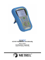
2,5 kV Insulation / Continuity MI 3121H Instruction manual Version 1.2, Code no.: 20 751 674 Distributor: Manufacturer: METREL d.d. Ljubljanska cesta 77 1354 Horjul Slovenia web site: http://www.metrel.si e-mail: [email protected] Mark on your equipment certifies that this equipment meets the requirements of the EU (European Union) concerning safety and electromagnetic compatibility regulations © 2010 METREL The trade names Metrel, Smartec, Eurotest, Autosequence are trademarks registered or pending in Europe and other countries. No part of this publication may be reproduced or utilized in any form or by any means without permission in writing from METREL. 2 MI 3121H Smartec 2,5 kV Insulation / Continuity 1 2 3 4 5 6 7 Table of contents Preface.........................................................................................................................5 Safety and operational considerations.....................................................................6 2.1 Warnings and notes...............................................................................................6 2.2 Battery and charging .............................................................................................8 2.2.1 New battery cells or cells unused for a longer period .....................................9 2.2.2 Auto Power Off ...............................................................................................9 2.3 Standards applied................................................................................................10 Instrument description.............................................................................................11 3.1 Front panel ..........................................................................................................11 3.2 Connector panel ..................................................................................................12 3.3 Back panel...........................................................................................................13 3.4 Display organization ............................................................................................14 3.4.1 Function field ................................................................................................14 3.4.2 Result fields..................................................................................................14 3.4.3 Message field ...............................................................................................15 3.4.4 Auxiliary monitor...........................................................................................15 3.4.5 Battery indication..........................................................................................16 3.4.6 Other messages ...........................................................................................16 3.4.7 Backlight.......................................................................................................16 3.5 Instrument set and accessories ...........................................................................17 3.5.1 Standard set .................................................................................................17 3.5.2 Optional accessories ....................................................................................17 Instrument operation................................................................................................18 4.1 Function selection................................................................................................18 4.2 Settings ...............................................................................................................19 4.2.1 Initial settings................................................................................................19 4.2.2 Date and time ...............................................................................................20 Measurements ..........................................................................................................21 5.1 Insulation resistance............................................................................................21 5.1.1 Insulation resistance measuring procedure ..................................................21 5.1.2 The DAR and PI diagnostic ..........................................................................23 5.1.3 Guard terminal..............................................................................................24 5.2 Resistance of earth connection and equipotential bonding .................................26 5.2.1 RLOW, 200 mA resistance measurement ....................................................26 5.2.2 Continuous 7 mA resistance measurement CONT.......................................27 5.2.3 Compensation of test leads resistance.........................................................29 5.3 Voltage and frequency.........................................................................................30 Data handling ............................................................................................................32 6.1 Memory organization ...........................................................................................32 6.2 Data structure ......................................................................................................32 6.3 Storing test results...............................................................................................33 6.4 Recalling test results ...........................................................................................33 6.5 Clear / recall options............................................................................................34 6.5.1 Clearing complete memory content..............................................................34 6.5.2 Clearing individual results at selected location .............................................35 6.6 Communication....................................................................................................36 Maintenance..............................................................................................................37 7.1 Fuse replacement................................................................................................37 7.2 Cleaning ..............................................................................................................37 3 MI 3121H Smartec 2,5 kV Insulation / Continuity Table of contents 7.3 Periodic calibration ..............................................................................................37 7.4 Service ................................................................................................................37 8 Technical specifications ..........................................................................................38 8.1 Insulation resistance............................................................................................38 8.2 Continuity ............................................................................................................39 8.2.1 Resistance RLOW........................................................................................39 8.2.2 Resistance CONT ........................................................................................39 8.3 Voltage, frequency...............................................................................................39 8.3.1 Voltage .........................................................................................................39 8.3.2 Frequency ....................................................................................................39 8.4 General data........................................................................................................40 9 Appendix A - Accessories for specific measurements .........................................41 4 MI 3121H Smartec 2,5 kV Insulation / Continuity Preface 1 Preface Congratulations on your purchase of the instrument and its accessories from METREL. The instrument was designed on basis of rich experience, acquired through many years of dealing with insulation and resistance test equipment. The multifunctional hand-held insulation tester Smartec 2,5 kV Insulation / Continuity is intended in general for the following tests and measurements: True r.m.s. voltage and frequency, Insulation resistance with high d.c. test voltage up to 2,5kV, Resistance to earth connection and equipotential bonding plus continuous resistance measurement. The custom designed display with backlight offers easy reading of results, indications, and measurement parameters. The operation of the unit is clear and simple – the operator does not need any special training (except reading this instruction manual) to operate the instrument. In order for operator to be familiar enough with performing measurements in general and in typical applications it is advisable to read Metrel handbook Guide for testing and verification of low voltage installations. The instrument is equipped with all necessary accessories for comfortable testing. 5 MI 3121H Smartec 2,5 kV Insulation / Continuity Warnings and notes 2 Safety and operational considerations 2.1 Warnings and notes In order to reach high level of operator’s safety while carrying out various tests and measurements using Smartec 2,5 kV Insulation / Continuity test equipment, as well as to keep the equipment undamaged, it is necessary to consider the following general warnings: Warning on the instrument means »Read the Instruction manual with special care to safety operation«. The symbol requires an action! If the test equipment is used in a manner that is not specified in this user manual, the protection provided by the equipment might be impaired! Read this user manual carefully, otherwise use of the instrument may be dangerous for the operator, for the instrument or for the equipment under test! Do not use the instrument and accessories if any damage is noticed! In case a fuse has blown follow the instructions in this manual to replace it! Consider all generally known precautions in order to avoid risk of electric shock while dealing with hazardous voltages! Only a competent authorized person is allowed to carry out service intervention or adjustment and calibration procedure! Use only standard or optional test accessories supplied by your distributor! Consider that older and some of new optional test accessories compatible with this instrument meet overvoltage category CAT III / 300 V! It means that maximum allowed voltage between test terminals and ground is 300 V! Instrument contains rechargeable NiCd or NiMh battery cells. The cells should only be replaced with the same type as defined on the battery placement label or in this manual. Do not use standard alkaline battery cells while power supply adapter is connected, otherwise they may explode! Hazardous voltages exist inside the instrument. Disconnect all test leads, remove the power supply cable and switch off the instrument before removing battery compartment cover. All normal safety precautions have to be taken in order to avoid risk of electric shock when working on electrical installations! Warnings related to measurement functions: Insulation resistance Do not touch the test object during the measurement or before it is fully discharged! Risk of electric shock! Automatic discharge of capacitive object will take some time after the finished insulation resistance measurement. Actual voltage is displayed during discharging until voltage drops below 10 V. In no case you should disconnect test leads until tested object is completely discharged! 6 MI 3121H Smartec 2,5 kV Insulation / Continuity Warnings and notes Notes related to measurement functions: General If there is any irregular condition on input terminals then the selected measurement can't be performed. Insulation resistancecontinuity measurements shall be performed on deenergized objects, i.e. voltage between test terminals should be lower than 10 V! PASS / FAIL indication is enabled when limit is set to ON. Apply appropriate limit value for evaluation of measurement results. Insulation resistance When measuring insulation resistance between installation conductors all loads must be disconnected and all switches closed! The instrument automatically discharge tested object after finished measurement. Click the TEST key twice for continuous measurement. It is recommended to use the GUARD connection when high insulation resistance (>10G Ω) is measured. You need optional 2.5 kV 3-wire test lead. The guard terminal is internal impedance (660 kΩ) protected. The DAR and PI diagnostic is automatically calculated during insulation measurements. Continuity functions Parallel resistance paths and interfering currents in measured circuit will influence the test result! If necessary compensate test lead resistance before performing continuity measurement, see 5.2.3. Measurement of resistance of wire wound components like transformer or motor windings is possible only in continuous function due to great influence of the winding inductance. 7 MI 3121H Smartec 2,5 kV Insulation / Continuity Battery and charging 2.2 Battery and charging The instrument uses six AA size alkaline or rechargeable Ni-Cd or Ni-MH battery cells. Nominal operating time is declared for cells with nominal capacity of 2100 mAh. Battery condition is always present on the display when the instrument is turned on. In case the battery is weak, the instrument indicates this as shown in Figure 2.1. This indication appears for a few seconds and then the instrument turns itself off. Figure 2.1: Discharged battery indication The battery is charged whenever the power supply adapter is connected to the instrument. Internal circuit controls charging assuring maximum battery lifetime. The power supply socket polarity is shown in Figure 2.2. + Figure 2.2: Power supply socket polarity The instrument automatically recognizes the connected power supply adapter and begins charging. See the Figure 2.3. Symbols: Indication of battery charging Figure 2.3: Charging indication Before opening battery / fuse compartment cover, disconnect all accessories connected to the instrument and switch off the instrument. Insert cells correctly, otherwise the instrument will not operate and the battery could be damaged. Remove all battery cells from the battery compartment if the instrument is not used for a long period of time. Do not charge alkaline battery cells! Take into account handling, maintenance and recycling requirements that are defined by related regulations and manufacturers of alkaline or rechargeable batteries! Use only power supply adapter delivered from the manufacturer or distributor of the test equipment to avoid possible fire or electric shock! 8 MI 3121H Smartec 2,5 kV Insulation / Continuity Battery and charging 2.2.1 New battery cells or cells unused for a longer period Unpredictable chemical processes can occur during charging of new battery cells or cells that were unused for a longer period (more than 3 months). Ni-MH and Ni-Cd battery cells are affected to capacity degradation (sometimes called as memory effect). As a result, the instrument operation time can be significantly reduced. Recommended procedure for recovering battery cells: Procedure ¾ Completely charge the battery. Notes At least 14h with in-built charger. Use the instrument for normal testing until the unit displays the “Bat” symbol on screen. ¾ Completely discharge the battery. ¾ Repeat the charge / discharge cycle for Four cycles are recommended. at least twice. Complete discharge / charge cycle can be performed automatically for each cell using external intelligent battery charger. Notes: The charger in the instrument is a pack cell charger. This means that the battery cells are connected in series during the charging. The battery cells have to be equivalent (same charge condition, same type and age). One different battery cell can cause an improper charging and incorrect discharging during normal usage of the entire battery pack (it results in heating of the battery pack, significantly decreased operation time, reversed polarity of defective cell,…). If no improvement is achieved after several charge / discharge cycles, then each battery cell should be checked (by comparing battery voltages, testing them in a cell charger, etc). It is very likely that only some of the battery cells are deteriorated. The effects described above should not be confused with the normal decrease of battery capacity over time. Battery also loses some capacity when it is repeatedly charged / discharged. Actual decreasing of capacity, versus number of charging cycles, depends on battery type. This information is provided in the technical specification from battery manufacturer. 2.2.2 Auto Power Off The Instrument has the Auto Power Off function. If the instrument is Turn On and inactive for period of 15 minutes, it automatically Turn Off. 9 MI 3121H Smartec 2,5 kV Insulation / Continuity Standards applied 2.3 Standards applied The MI 3121H Smartec 2,5 kV Insulation / Continuity instrument is manufactured and tested according to the following regulations, listed below. Electromagnetic compatibility (EMC) EN 61326 Electrical equipment for measurement, control and laboratory use – EMC requirements Class B (Hand held equipment used in controlled EM environments) Safety (LVD) Safety requirements for electrical equipment for measurement, control, and laboratory use – Part 1: General requirements Safety requirements for hand-held probe assemblies for electrical EN 61010 - 031 measurement and test EN 61010 - 1 Functionality EN 61557 Electrical safety in low voltage distribution systems up to 1000 V a.c. and 1500 V d.c. - Equipment for testing, measuring or monitoring of protective measures Part 1 General requirements Part 2 Insulation resistance Part 4 Resistance of earth connection and equipotential bonding Part 10 Combined measuring equipment Note about EN and IEC standards: Text of this manual contains references to European standards. All standards of EN 6xxxx (e.g. EN 61010) series are equivalent to IEC standards with the same number (e.g. IEC 61010) and differ only in amended parts required by European harmonization procedure. 10 MI 3121H Smartec 2,5 kV Insulation / Continuity Front panel 3 Instrument description 3.1 Front panel 1 2 3 4 5 6 7 12 11 10 9 8 Figure 3.1: Front panel Legend: 1 2 3 4 5 LCD TEST UP DOWN MEM Store / recall / clear tests in memory of instrument. 6 Function selector Select test function. 7 Backlight 8 ON / OFF 9 CAL Changes backlight level. Switches the instrument power on or off. The instrument automatically turns off 15 minutes after the last key was pressed. Compensates test leads resistance in RLOW and CONT functions. Selects the parameters in selected function. 10 11 12 TAB PASS FAIL Custom display with backlight. Starts / stops a measurement. Modifies selected parameter. Indicate acceptance of result. 11 MI 3121H Smartec 2,5 kV Insulation / Continuity Connector panel 3.2 Connector panel Figure 3.2: Connector panel Legend: 1 Test connector 2 Protection cover 3 Charger socket 4 USB connector 5 PS/2 connector Measuring inputs / outputs, connection of measuring cables. Protects from simultaneous access to test connector and power supply adapter socket / communication connectors. Connection of power supply adapter. Communication with PC USB (1.1) port. Communication with PC serial port. Warnings! Maximum allowed voltage between any test terminal and ground is 600 V! Maximum allowed voltage between test terminals is 600 V! Maximum short-term voltage of external power supply adapter is 14 V! 12 MI 3121H Smartec 2,5 kV Insulation / Continuity 3.3 Back panel Figure 3.3: Back site Legend: 1 2 3 4 5 6 Side belt Battery compartment cover Fixing screw for battery compartment cover Back panel information label Holder for inclined position of the instrument Magnet for fixing instrument close to tested item Figure 3.4: Battery compartment Legend: 1 2 3 Battery cells Serial number label Fuse Size AA, alkaline or rechargeable NiMH / NiCd M 0.315 A, 250 V 13 Back site MI 3121H Smartec 2,5 kV Insulation / Continuity Display organization 3.4 Display organization Function field Result field Analog results display Test voltage selection field Figure 3.5: Typical display Message field CAL LIM MEM RCL LOC OBJ PI DAR Auxiliary monitor Battery indication 3.4.1 Function field The function field displays currently selected function. Selected function is Insulation resistance. Selected function is 7 mA Continuous resistance measurement. Selected function is 200 mA Resistance to earth connection and equipotential bonding measurement. Selected function is Voltage / frequency measurement. 3.4.2 Result fields Measuring results are displayed in numeric and analog representation with evaluation result in case the limits are selected. 14 MI 3121H Smartec 2,5 kV Insulation / Continuity Display organization Numeric readout of measurement result Measurement result is inside pre-set limits (PASS). Measurement result is out of pre-set limits (FAIL). Analog presentation of measured result. … 3.4.3 Message field In the message field, different warnings and messages are displayed. Warning! Read the User Manual with special care! Warning! Dangerous voltage is applied to the test terminals. Measurement is implemented. CAL Test leads resistance in CONTINUITY tests is compensated. LIM Indicates that limit value can be set. MEM Offers storing of measurement result. RCL Indicates that recall memory is active. LOC Indicates location number in installation structure. OBJ Indicates object number in installation structure. PI DAR Indicates Polarization Index result in the Insulation function. Indicates Dielectric Absorption Ratio result in the Insulation function. 3.4.4 Auxiliary monitor The monitor shows additional result, test parameter or message. 15 MI 3121H Smartec 2,5 kV Insulation / Continuity Display organization 3.4.5 Battery indication In the menu line, the name of the selected function is displayed. Additional information about active cursor / TEST keys and battery condition are shown. Battery capacity indication. Low battery. Battery is too weak to guarantee correct result. Replace or recharge the battery cells. Recharging in progress (moving segments if power supply adapter is connected). 3.4.6 Other messages HW version of the instrument Version of built in FW. Service intervention required. Locked high backlight intensity. 1st sub result in RLOW function. 2nd sub result in RLOW function. Fuse F1 has blown or has not been inserted (CONTINUITY function) Setting of limit (Resistance value). 3.4.7 Backlight With the BACKLIGHT key the backlight can be adjusted. Click Pressed for 1 s Toggle backlight intensity level. Locks-on high backlight. It keeps until power off or next click on the key BACKLIGHT. 16 MI 3121H Smartec 2,5 kV Insulation / Continuity Instrument set and accessories 3.5 Instrument set and accessories 3.5.1 Standard set Instrument MI 3121H Instruction manual Calibration certificate 2.5 kV test lead, 2 x 1.5 m Test probe, 2 pcs Crocodile clip, 2 pcs NiMH battery cell, type AA, 6 pcs Power supply adapter CD with instruction manual, and “Guide for testing and verification of low voltage installations” handbook Soft hand strap 3.5.2 Optional accessories See the attached sheet for a list of optional accessories that are available on request from your distributor. 17 MI 3121H Smartec 2,5 kV Insulation / Continuity Function selection 4 Instrument operation 4.1 Function selection For selecting test function, the FUNCTION SELECTOR shall be used. Keys: Select test / measurement function: FUNCTION SELECTOR (BACK / NEXT) UP/DOWN TAB TEST MEM CAL <VOLT> Voltage and frequency and phase sequence. <INS> Insulation resistance measurement. <RLOW / CONT> Resistance to earth connection and equipotential bonding / continuous resistance measurement. Selects sub-function in selected measurement function. Selects the test parameter to be set or modified. Runs selected test / measurement function. Stores measured results / recalls stored results. Compensation of test leads resistance. Keys in test parameter field: UP/DOWN TAB FUNCTION SELECTOR MEM Changes the selected parameter. Selects the next measuring parameter. Toggles between the main functions. Stores measured results / recalls stored results. General rule regarding enabling parameters for evaluation of measurement / test result: No limit values. Results will be marked as PASS or FAIL in accordance with Value selected limit. --Parameter See Chapter 5 for more information about the operation of the instrument test functions. 18 MI 3121H Smartec 2,5 kV Insulation / Continuity Settings 4.2 Settings The instrument offers additional functions by the following combinations of the keys during power on. Combinations are: UP + ON TAB + ON Opens settings menu. Resets the instrument to initial factory settings. Different instrument options can be set in the settings menu. Options are: Setting the instrument to initial values, Setting the date and time. Figure 4.1: Options in Settings menu Keys: UP / DOWN TEST Function selector Selects appropriate option. Enters selected option. Exits back to main function menu. 4.2.1 Initial settings Selecting this option will allow the user to reset the instrument settings and measurement parameters and limits to the manufacturers standard values. Figure 4.2: Initial settings display Keys: TEST Function selector Restores default settings. Exits back to main function menu without changes. Warning: Custom made settings will be lost when this option is used! If the batteries are removed for more than 1 minute, the custom made settings will be lost. 19 MI 3121H Smartec 2,5 kV Insulation / Continuity Settings The default setup is listed below: Instrument setting Default value Function Sub-function Insulated resistance Continuity RLOW CONT Parameters / limit value No limit, Utest = 500 V RLOW No limit No limit Note: Initial settings (reset of the instrument) can be recalled also if the TAB key is pressed while the instrument is switched on. 4.2.2 Date and time Selecting this option will allow the user to set the date and time of the unit. Figure 4.3: Setting date and time Keys: TAB UP / DOWN TEST Function selector Selects the field to be changed. Modifies selected field. Confirms new setup and exits. Exits back to main function menu. Indications: Set day. Set month. Set year. Set hour. Set minute. Warning: If the batteries are removed for more than 1 minute, the set time will be lost. 20 MI 3121H Smartec 2,5 kV Insulation / Continuity Insulation resistance 5 Measurements 5.1 Insulation resistance 5.1.1 Insulation resistance measuring procedure Insulation resistance measurement is performed in order to assure safety against electric shock through insulation. It is covered by the EN 61557-2 standard. Typical applications are: Insulation resistance between conductors of installation, Insulation resistance of non-conductive rooms (walls and floors), Insulation resistance of ground cables, Resistance of semi-conductive (antistatic) floors. See chapter 4.1 Function selection for instructions on key functionality. Figure 5.1: Insulation resistance Test parameters for insulation resistance measurement Uiso Limit Test voltage [100 V, 250 V, 500 V, 1000 V, 2.5 kV] Minimum insulation resistance [OFF, 0.01 MΩ ÷ 200 MΩ] 21 MI 3121H Smartec 2,5 kV Insulation / Continuity Insulation resistance Test circuits for insulation resistance L1 L2 L3 N PE mains voltage switched off closed switches loads disconnected Figure 5.2: Connection of 2-wire test lead L1 L2 L3 N PE mains voltage switched off closed switches loads disconnected Figure 5.3: Connection of optional 3-wire test lead (A 1319) Insulation resistance measuring procedure Select the INS function using the BACK / NEXT keys of function selector. Set the required test voltage (Press the TAB key then use arrows). Enable and set limit value (optional). Disconnect tested installation from mains supply (and discharge insulation as required). Connect test lead to the top of the instrument and to the item to be tested (see Figure 5.2 and Figure 5.3). Press the TEST key to perform the measurement (double click for continuous measurement and later press to stop the measurement). After the measurement is finished wait until tested item is fully discharged. Store the result by pressing the MEM key (optional). 22 MI 3121H Smartec 2,5 kV Insulation / Continuity Insulation resistance Figure 5.4: Example of insulation resistance measurement result Displayed results: Insulation resistance – value, Insulation resistance – analog presentation, Test voltage – actual value. Test voltage – nominal value. 5.1.2 The DAR and PI diagnostic The DAR and PI diagnostic is automatically calculated during insulation measurements. DAR is ratio of Insulation Resistance values measured after 15s and after 1 minute. The DC test voltage is present during the whole period of the measurement. When internal timer reaches 15 seconds, RISO(15s) is stored into the internal memory (short beep is generated). When internal timer reaches 1 minute, RISO(1min) is stored into the internal memory (short beep is generated). The DAR factor is calculated and stored into the internal memory. The DAR icon becomes also active to signalize during measurement, that DAR factor has been calculated. DAR = R (1 min ) R (15s ) iso iso PI is the ratio of Insulation Resistance values measured after 1 minute and after 10 minutes. The DC test voltage is present during the whole period of the measurement When internal timer reaches 10 minute, RISO(10min) is stored into the internal memory (short beep is generated). The PI factor is calculated and stored into the internal memory. The PI icon becomes also active to signalize during measurement, that PI factor has been calculated. PI = R (10 min ) R (1 min ) iso iso It is possible to switch between DAR, PI and insulation results during measurement by pressing the TAB key. See the Figure 5.5 and Figure 5.6. 23 MI 3121H Smartec 2,5 kV Insulation / Continuity Figure 5.5: DAR result displayed during measurement (result flashing) Insulation resistance Figure 5.6: PI result displayed during measurement (result flashing) After measurement is finished it is possible to switch between DAR, PI, also R60 and insulation results. R60 is the resistance value measured 1minute (60 seconds) after start of the measurement. Simply keep pressing (few seconds) the TAB key to enter to the sub results menu. Here you can list sub results (DAR, PI, and R60) with normal pressing on the TAB key. Automatically turn back from sub result menu is occurred, after all sub results are displayed once. See the Figure 5.7, Figure 5.8 and Figure 5.9. Figure 5.7: DAR result Figure 5.8: PI result Figure 5.9: R60 value displayed after measurement displayed after measurement displayed after measurement For additional information regarding PI and DAR diagnostic, please refer to Metrel’s handbook Modern Insulation Testing. 5.1.3 Guard terminal The purpose of the GUARD terminal is to lead away potential leakage currents (e.g. surface currents), which are not a result of the measured insulation material itself but of the surface contamination and moisture. This current interferes with the measurement i.e. the Insulation Resistance result is influenced by this current. The GUARD terminal is internally connected to the same potential as the negative test terminal (black one). The GUARD test alligator should be connected to measured object so as to collect most of the unwanted leakage current, see the figure below. 24 MI 3121H Smartec 2,5 kV Insulation / Continuity Insulation resistance IL IM IM IL +OUT -OUT Ut IA +OUT -OUT Ut A IA IL GUARD A Figure 5.10: Connection of GUARD terminal to measured object where: Ut ........ Test voltage IL ......... Leakage current (resulted by surface dirt and moisture) IM ........ Material current (resulted by material conditions) IA ......... A-meter current Result without using GUARD terminal: RINS = Ut / IA = Ut / (IM + IL) …incorrect result. Result using GUARD terminal: RINS = Ut / IA = Ut / IM ……correct result. It is recommended to use the GUARD connection when high insulation resistance (>10G Ω) is measured. You need optional 2.5 kV 3-wire test lead (Figure 5.3). The guard terminal is internal impedance (660 kΩ) protected. 25 MI 3121H Smartec 2,5 kV Insulation / Continuity Continuity 5.2 Resistance of earth connection and equipotential bonding The resistance measurement is performed in order to assure that the protective measures against electric shock through earth bond connections are effective. Two sub-functions are available: RLOW - Earth bond resistance measurement according to EN 61557-4 (200 mA), CONT - Continuous resistance measurement performed with 7 mA. See chapter 4.1 Function selection for instructions on key functionality. Figure 5.11: 200 mA RLOW function example Test parameters for resistance measurement Test Limit Resistance measurement sub-function [RLOW, CONT] Maximum resistance [OFF, 0.1 Ω ÷ 20.0 Ω] 5.2.1 RLOW, 200 mA resistance measurement The resistance measurement is performed with automatic polarity reversal of the test voltage. Test circuit for RLOW measurement MPEC....Main Potential Equilizing Collector PCC....Protection Conductor Collector PCC3 PCC1 PCC2 MPEC extension lead Figure 5.12: Connection of 2-wire test lead plus optional extension lead 26 MI 3121H Smartec 2,5 kV Insulation / Continuity Continuity Resistance to earth connection and equipotential bonding measurement procedure Select continuity function (RLOW or CONT) using the BACK / NEXT keys of function selector. Set sub-function to RLOW. Enable and set limit (optional). Connect test lead to the top of the instrument. Compensate the test leads resistance (if necessary, see section 5.2.3). Disconnect from mains supply and discharge installation to be tested. Connect the test leads to the appropriate PE wiring (see Figure 5.12). Press the TEST key to perform the measurement. After the measurement is finished store the result by pressing the MEM button (optional). Figure 5.13: Example of RLOW result Displayed result: Main RLOW resistance. Sub results checking Press the key TAB for a few seconds. The instrument will display sub result r1. Click the key TAB. The instrument will display sub result r2. Next click on the key TAB will return the instrument to display main result. 5.2.2 Continuous 7 mA resistance measurement CONT In general, this function serves as standard Ω-meter with a low testing current. The measurement is performed continuously without polarity reversal. The function can also be applied for testing continuity of inductive components. 27 MI 3121H Smartec 2,5 kV Insulation / Continuity Continuity y z x R S T Test circuit for CONT resistance measurement Figure 5.14: 2-wire test lead application Continuous resistance measurement procedure Select continuity function RLOW or CONT using the BACK / NEXT keys of function selector. Set sub-function CONT. Enable and set the limit (optional). Connect test lead to the instrument. Compensate test leads resistance (if necessary, see section 5.2.3). Disconnect from mains supply and discharge the object to be tested. Connect test leads to the tested object (see Figure 5.14). Press the TEST key to begin performing a continuous measurement. Press the TEST key to stop measurement. After the measurement is finished, store the result (optional). Figure 5.15: Example of continuous resistance measurement Displayed result: Resistance. Note: Continuous buzzer sound indicates that measured resistance is less than 2 Ω. 28 MI 3121H Smartec 2,5 kV Insulation / Continuity Continuity 5.2.3 Compensation of test leads resistance This chapter describes how to compensate for test leads resistance in both continuity functions (RLOW and CONT). Compensation is required to eliminate the influence of test leads resistance and the internal resistances of the instrument on the measured resistance. The lead compensation is therefore a very important feature to obtain correct result. Once compensation has been performed, the compensation symbol ( ) appears on the screen. Each of RLOW and CONT has each own compensation. Circuits for compensating the resistance of test leads Figure 5.16: Shorted test leads Compensation of test leads resistance procedure Select the any continuity function using the function switch. Connect test lead to the top of the instrument and short the test leads together (see Figure 5.16). Press TEST to perform resistance measurement. Press the CAL key to compensate leads resistance. Note: The limit value for lead compensation is 5 Ω. 29 MI 3121H Smartec 2,5 kV Insulation / Continuity Voltage and Frequency 5.3 Voltage and frequency In the VOLT menu the measured voltage and frequency are displayed. See 4.1 Function selection for instructions on key functionality, Figure 5.17: Voltage and frequency display Circuits for voltage measurement L1 L2 L3 N PE N Ro PE L RE Figure 5.18: Connection of 2-wire test lead 30 MI 3121H Smartec 2,5 kV Insulation / Continuity Voltage and Frequency Voltage measurement procedure Select the VOLT function. Connect test lead to the instrument. Connect test leads to the tested object (see Figure 5.18). Store voltage measurement result (optional). Measurement starts immediately after selection of VOLT function. Figure 5.19: Example of voltage measurement Displayed results: Voltage between test terminals – value, Voltage between test terminals – analog presentation, Frequency. 31 MI 3121H Smartec 2,5 kV Insulation / Continuity Memory organization 6 Data handling 6.1 Memory organization Measurement results together with all relevant parameters can be stored in the instrument’s memory. 6.2 Data structure The instrument’s memory place is divided into 2 levels each containing 199 locations. The number of measurements that can be stored into one location is not limited. The data structure describes the identity of the measurement (which object, location). This organization helps to handle with data in a simple and effective manner. The main advantages of this system are: Test results can be organized and grouped in a structured manner that reflects the structure of typical electrical installations. Browsing through structures and results is simple. Test reports can be created with no or little modifications after downloading results to a PC. Figure 6.1: Save / recall test menu Fields in memory organization: Location number is 6. Number of stored results at currently selected location / object (6/16) is 11. Object number is 16. Number of stored results at currently selected location / object (6/16) is 11. 32 MI 3121H Smartec 2,5 kV Insulation / Continuity Storing test results 6.3 Storing test results After the completion of a test, the results and parameters are ready for storing (MEM is displayed with result). By pressing the MEM key, the user can store the results. Keys in save test menu - data structure field: Selects the location element (Object / Location) Selects number of selected location element (1 to 199) Saves test results to the selected location and returns to the measuring menu. TAB UP / DOWN MEM Function selector / TEST Exits back to main function menu. Notes: The instrument offers storing the result to the last selected location by default. Press the MEM key twice to store the measurement to the same location. 6.4 Recalling test results Press shortly the MEM key in a main function menu when there is no result available for indication). storing (no Keys in recall memory menu (data structure selected): Selects the location element (Object / Location). TAB Selects number of selected location element. UP / DOWN Opens last stored result in selected location. MEM Function selector / Exits back to main function menu. TEST Keys in recall memory menu (measurements selected): UP / DOWN MEM Function selector / TEST Displays next / previous stored measurement. Returns to main MEM menu. Exits back to main function menu. , Figure 6.2: Example of recalled measurement result 33 MI 3121H Smartec 2,5 kV Insulation / Continuity Clear / Recall 6.5 Clear / recall options Press the MEM key in a main function menu for few seconds to activate possibility for clearing or recalling results. Figure 6.3: Entering menu for recall / clear options on stored results Keys in recall / clear memory menu: UP DOWN TEST Opens menu to clear result at currently selected location. Opens menu to clear all results. Confirms selected clear option (CLR All, see 6.5.1; CLR, see 6.5.2) Opens last selected location to recall the results or change location, see 6.4. Function selector / Exit back to main function menu. MEM / TAB 6.5.1 Clearing complete memory content After selection of CLEAR ALL, the instrument will display the following: Initial display to clear all memory Required confirmation to clear all Figure 6.4: Clear all memory Keys in clear all memory menu: TEST Function selector / TAB Confirms clearing of complete memory content. Exits back to main function menu without changes. 34 MI 3121H Smartec 2,5 kV Insulation / Continuity Clear / Recall Figure 6.5: Clearing memory in progress 6.5.2 Clearing individual results at selected location After selection of CLEAR result, the instrument will display the following: Figure 6.6: Clear measurements menu Keys in clearing individual results menu (data structure field selected): TAB UP / DOWN TEST Selects the location element (Object / Location). Selects number of selected location element. Opens last result at selected location UP / DOWN TEST Function selector / MEM Rotate through stored results to select one to clear Clears current recalled result and recalls the next one. Exits back to main function menu without changes. Figure 6.7: Clearing in progress Figure 6.8: Display after finished clear 35 MI 3121H Smartec 2,5 kV Insulation / Continuity Communication 6.6 Communication Stored results can be transferred to a PC. A special communication program on the PC automatically identifies the instrument and enables data transfer between the instrument and the PC. There are two communication interfaces available on the instrument: USB or RS 232. The instrument automatically selects the communication mode according to detected interface. USB interface has priority. Figure 6.9: Interface connection for data transfer over PC COM port How to transfer stored data: RS 232 communication: connect a PC COM port to the instrument PS/2 connector using the PS/2 - RS232 serial communication cable; USB communication: connect a PC USB port to the instrument USB connector using the USB interface cable. Switch on the PC and the instrument. Run the EuroLink PRO program. The PC and the instrument will automatically recognize each other. The instrument is prepared to download data to the PC. The program EuroLink PRO is a PC software running on Windows 95/98, Windows NT, Windows 2000, Windows XP, Windows Vista, Windows 7. Read the file README.TXT on CD for instructions about installing and running the program. Note: USB drivers should be installed on PC before using the USB interface. Refer to USB installation instructions available on installation CD. 36 MI 3121H Smartec 2,5 kV Insulation / Continuity Maintenance 7 Maintenance Unauthorized persons are not allowed to open the Smartec 2,5 kV Insulation / Continuity instrument. There are no user replaceable components inside the instrument, except the fuse and battery under rear cover. 7.1 Fuse replacement There is a fuse under back cover of the Smartec 2,5 kV Insulation / Continuity instrument. F1 M 0.315 A / 250 V, 20×5 mm This fuse protects internal circuitry for continuity functions if test probes are connected to the mains supply voltage by mistake during measurement. Warnings: Disconnect all measuring accessory and switch off the instrument before opening battery / fuse compartment cover, hazardous voltage inside! Replace blown fuse with original type only, otherwise the instrument may be damaged and/or operator’s safety impaired! Position of fuses can be seen in Figure 3.4 in chapter 3.3 Back panel. 7.2 Cleaning No special maintenance is required for the housing. To clean the surface of the instrument use a soft cloth slightly moistened with soapy water or alcohol. Then leave the instrument to dry totally before use. Warnings: Do not use liquids based on petrol or hydrocarbons! Do not spill cleaning liquid over the instrument! 7.3 Periodic calibration It is essential that the test instrument is regularly calibrated in order that the technical specification listed in this manual is guaranteed. We recommend an annual calibration. Only an authorized technical person can do the calibration. Please contact your dealer for further information. 7.4 Service For repairs under warranty, or at any other time, please contact your distributor. 37 MI 3121H Smartec 2,5 kV Insulation / Continuity Technical specifications 8 Technical specifications 8.1 Insulation resistance Insulation resistance (nominal voltages 100 VDC and 250 VDC) Measuring range according to EN61557 is 0.15 MΩ ÷ 999.9 MΩ. Accuracy Measuring range (MΩ) Resolution (MΩ) 0.01 0.00 ÷ 19.99 ±(5 % of reading + 3 digits) 0.1 20.0 ÷ 199.9 ±(10 % of reading) 1 200 ÷ 999 ±(20 % of reading) Insulation resistance (nominal voltages 500 VDC, 1000 VDC and 2500 VDC) Measuring range according to EN61557 is 0.15 MΩ ÷ 100 GΩ. Accuracy Measuring range (Ω) Resolution (MΩ) 0.01 0.00M ÷ 19.99M ±(5 % of reading + 3 digits) 0.1 20.0M ÷ 199.9M ±(5 % of reading) 1 200M ÷ 999M 10 ±(10 % of reading) 1.00G ÷ 4.99G 10 ±(20 % of reading) 5.00G ÷ 19.99G 100 ±(20 % of reading) 20.0G ÷ 99.9G Dielectric absorption ratio DAR Display range DAR 0.01 ÷ 9.99 10.0 ÷ 100.0 Resolution 0.01 0.1 Accuracy ±(5% of reading + 2digits) ±(5% of reading) Polarization index PI Display range PI Resolution Accuracy 0.01 ÷ 9.99 10.0 ÷ 100.0 0.01 0.1 ±(5% of reading + 2digits) ±(5% of reading) Voltage Measuring range (V) 0 ÷ 1999 2.00k ÷ 3.00k Resolution (V) 1 10 Accuracy ±(3 % of reading + 3 digits) ±(3 % of reading) Nominal voltages .............................. 100 VDC, 250 VDC, 500 VDC, 1000 VDC, 2500 VDC Open circuit voltage .......................... -0 % / +20 % of nominal voltage Measuring current............................. min. 1 mA at RN=UN×1 kΩ/V Short circuit current........................... max. 3 mA The number of possible tests............ > 1200, with a fully charged battery Auto discharge after test. Specified accuracy is valid up to 100 MΩ if relative humidity is move over 85 %. In case the instrument gets moistened, the results could be impaired. In such case, it is recommended to dry the instrument and accessories for at least 24 hours. The error in operating conditions could be at most the error for reference conditions (specified in the manual for each function) ±5 % of measured value. 38 MI 3121H Smartec 2,5 kV Insulation / Continuity Technical specifications 8.2 Continuity 8.2.1 Resistance RLOW Measuring range according to EN61557 is 0.16 Ω ÷ 1999 Ω. Accuracy Measuring range R (Ω) Resolution (Ω) 0.01 0.00 ÷ 19.99 ±(3 % of reading + 3 digits) 0.1 20.0 ÷ 199.9 ±(5 % of reading) 1 200 ÷ 1999 ±(10 % of reading) Open-circuit voltage.......................... 6.5 VDC ÷ 9 VDC Measuring current............................. min. 200 mA into load resistance of 2 Ω Test lead compensation.................... up to 5 Ω The number of possible tests ........... > 2000, with a fully charged battery Automatic polarity reversal of the test voltage. 8.2.2 Resistance CONT Measuring range (Ω) 0.0 ÷ 19.9 20 ÷ 1999 Accuracy ±(5 % of reading + 3 digits) ±(10 % of reading) Resolution (Ω) 0.1 1 Open-circuit voltage.......................... 6.5 VDC ÷ 9 VDC Short-circuit current .......................... max. 8.5 mA Test lead compensation.................... up to 5 Ω 8.3 Voltage, frequency 8.3.1 Voltage Measuring range (V) 0.0 ÷ 99.9 100 ÷ 550 Resolution (V) 0.1 1 Accuracy ±(3 % of reading + 3 digits) Result type........................................ True r.m.s. (trms) Nominal frequency range.................. 0 Hz, 15 Hz ÷ 500 Hz 8.3.2 Frequency Measuring range (Hz) 0.00 ÷ 19.99 20.0 ÷ 199.9 200 ÷ 500 Resolution (Hz) 0.01 0.1 1 Nominal voltage range ...................... 10 V ÷ 550 V 39 Accuracy ±(0.2 % of reading + 1 digit) MI 3121H Smartec 2,5 kV Insulation / Continuity 8.4 Technical specifications General data Power supply voltage........................ 9 VDC (6×1.5 V battery or accu, size AA) Operation .......................................... typical 13 h Charger socket input voltage ............ 12 V ± 10 % Charger socket input current............. 400 mA max Battery charging current.................... 250 mA (internally regulated) Overvoltage category........................ 600 V CAT III, 300 V CAT IV Protection classification .................... double insulation Pollution degree................................ 2 Protection degree ............................. IP 40 Display ............................................ custom liquid crystal display with backlight Dimensions (w × h × d) ..................... 14 cm × 8 cm × 23 cm Weight ............................................ 0.85 kg, without battery cells Reference conditions Reference temperature range........... 10 °C ÷ 30 °C Reference humidity range................. 40 %RH ÷ 70 %RH Operation conditions Working temperature range .............. 0°C ÷ 40 °C Maximum relative humidity ............... 95 %RH (0 °C ÷ 40 °C), non-condensing Storage conditions Temperature range ........................... -20 °C ÷ +70 °C Maximum relative humidity ............... 90 %RH (-10 °C ÷ +40 °C) 80 %RH (40 °C ÷ 60 °C) Maximum operation voltage.............. 600 V a.c. Communication transfer speed RS 232.............................................. 115200 baud USB .................................................. 256000 baud The error in operating conditions could be at most the error for reference conditions (specified in the manual for each function) +1 % of measured value + 1 digit, unless otherwise specified in the manual for particular function. 40 MI 3121H Smartec 2,5 kV Insulation / Continuity Accessory for specific measurements 9 Appendix A - Accessories for specific measurements The table below presents standard and optional accessories required for specific measurement. The accessories marked as optional may also be standard ones in some sets. Please see attached list of standard accessories for your set or contact your distributor for further information. Function Insulation resistance INS Continuity, 200 mA RLOW Continuity. 7 mA CONT Voltage, frequency Suitable accessories (Optional with ordering code A….) 2.5 kV test lead, 2 x 1.5 m 2.5 kV test lead, 3 x 1.5 m (A 1319) 2.5 kV test lead, 2 x 1.5 m Test lead, black, 4 m (A 1154) 2.5 kV test lead, 2 x 1.5 m Test lead, black, 4 m (A 1154) 2.5 kV test lead, 2 x 1.5 m 41 MI 3121H Smartec 2,5 kV Insulation / Continuity 42 Accessory for specific measurements MI 3121H Smartec 2,5 kV Insulation / Continuity 43 Accessory for specific measurements MI 3121H Smartec 2,5 kV Insulation / Continuity 44 Accessory for specific measurements