1
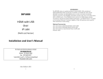
Panel View
CIP900-IP-T Transmitter
Short press
Switch to Video or Graphic
mode
Long press
(*)Anti-Dither Mode
2 (Button 2)
Press and Hold at
Power ON until
Green LED blinking
3 Red LED
(System status)
4 Green LED
(Power/Link
status)
5 Remote Power
On/Off (optional)
No. Component
1 HDMI (or DVI-D)
Loop-out
Description
HDMI (or DVI-D) Loop-out for Local Monitor.
Short press
Long press
2 (Button 1)
Press and Hold at
Power ON until
Green and Red
LED blinking
3
6 Link ID
Get and Use EDID from
Loop-out monitor
Green Blinking/Red Off: System is starting up.
Green On/Red Blinking: Linking or waiting HDMI
input source.
Green On/Red On: Connection established.
Connects to PC motherboard for Remote Power
On/Off.
4 bit DIP switch for 16 ID settings. To make
Transmitter/Receiver as a pair or group, the
transmitter and receiver must be set with the same
Link ID.
Connects to Gigabit switch or directly to
CIP900-IP-R
Switch video to Remote or
Loop-out monitor.
7 Gigabit Ethernet
Output video to both
Remote and Loop-out
monitors.
8 RS-232 Control
(optional)
Provide Serial-over-IP function.
9 DC 5V In
System power input (DC 5V 2A)
Reset the unit to the
Factory default setting.
4