1
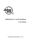
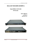
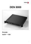
 AD Instruments AD6202HII user manual AD6202HII
H.264
Encoder
User Manual
V1.0
CHAPTER 1
AD Instruments AD6202HII user manual EQUIPMENT OVERVIEW
1.1 General introduction
AD6202HII H.264 Encoder is a professional broadcasting equipment can
satisfy the MPEG-4 AVC/H.264 standard, with encoding and multiplexing
function. The encoder supports 1-4 HDMI input (1-4 SDI/AV inputs optional ), it
can encode 1-4 channels sources synchronously. Also it has one group of ASI
input interface which can multiplex the TS from both encoder and other sources
into MPTS, and insert SI information.
The equipment has high quality performance with low cost, can be used
widely in various Digital TV broadcasting system and Digital TV Head-end
systems which have strict request on bandwidth.
1.2 Features
· Support H.264/AVC High Profile Level 4.0 Encoding, Hi-Tech Video
Preconditioning Algorithms;
·Audio Coding adopts MPEG-1 Audio Layer 2;
·1-4 Channels HDMI inputs (1-4 SDI / AV inputs optional);
·Single ASI input supporting multiplexing;
·HD Resolution of 720P, 1080I, 1080P;
·Support Multi-Programs output by ASI output and IP;
·Compatible with UDP protocol, support both Unicast and Multicast;
·Control LED display and Inspect setting parameters by button Operation;
·Set and Alter parameters via NMS Software.
Application
● Digital Cable TV Head-end;
1
● Satellite digital television broadcasting
● Digital Terrestrial Television
● Image Control
● Video on Demand (VOD)
● Distance Learning
● Video Conference
1.3 Performance Index
AD Instruments AD6202HII user manual Single ASI Input, BNC interface
1-4 Channel HDMI inputs( SDI optional)
Input
Resolution
Video
Input
Encoding
Audio
Input
1280×720_50p
H.264/AVC High Profile Level 4.0 (HD)
Coding Bit Rate
0.8Mbps-20Mbps (8Mbps by Factory Defaults, suggest to use no
less than 6Mbps if HD)
Bit Rate Control
CBR/VBR
GOP Type
IBBP
Video Preconditioning
Encoding
De-Interlacing, Noise abatement, sharpening
Sampling Rate
48KHz
Bit Depth
24 bit
Bit Rate
64Kb/s~384Kb/s
Multiplex 1 ASI input and 4 Channels Local Programs
Multiplexing
1920×1080_50p , 1920×1080_50i
1280×720_60p
1920×1080_60P , 1920×1080_60i
MPEG-1 Layer 2
Dual ASI output, BNC interface
TS Output
MPTSIPoutput,UDPProtocol,10/100M Ethernet
Port,Unicast and Multicast
LCD/KEY Operation, NMS, English Operation Interface
System
General
Update software via Web
Dimensions
482mmx400mmx44.5mm (L x W x H)
Weight
3.1kg
Temperature
0~45 (working),-20~ 80 (not working)
Power Supply
AC 110V~220V,50/60Hz
≤25W
Power
2
AD Instruments AD6202HII user manual Caution:
To ensure the stability of the equipment operation, all connection cable
on the rear panel interface is strictly prohibited to Hot-swappable.
When need to alter any of connection cable, need to be close the
power of the source-side device and this device before changes.
1.4 Functional Block Diagram
HDMI Input 1
A/V Preconditioning
H.264 Encoder
HDMI Input 2
A/V Preconditioning
H.264 Encoder
HDMI Input 3
A/V Preconditioning
H.264 Encoder
lexer
HDMI Input 4
A/V Preconditioning
ASI Output
Multip
MPTS
H.264 Encoder
IP Output
ASI Input
Program Analysis
Select Program
1.5 Outline and Description
1.5.1
4 channels HD inputs, 1 ASI input Sketch map of front panel:
2
4
Allin1 H.264 Encoder
Power
Alarm
CH1 Lock
CH2 Lock
CH3 Lock
CH4 Lock
ENTER
MENU
Broadcasting
TS Lock
1
3
6
5
1: LCD Interface
2: Power Signal Indication
3: 1#-4# Encoding Channel Lock Indication
4: Stream Overflow Alarm Indication
5: ASI Input Lock Indication
3
Digital Video
7
8
6: Up, Down, Left and Right Buttons
7: Confirm Button
8: Menu Button
1.5.2
AD Instruments AD6202HII user manual 4 channels HD inputs, 1 ASI input Sketch map of rear panel:
1
OUT
TS/IP
ASI
OUT
IN
HDMI 4
HDMI 3
HDMI 2
HDMI 1
AC110V-220V-50-60Hz
1
0
:
1
1
ETHERNET
2
3
4
5
6
7
8
9
10
1: IP Stream Output Interface;
2: Webmaster and Ethernet Interface;
3: DVB standard dual ASI output,BNC interface;
4: DVB standard single ASI input, BNC interface;
5: 4th HDMI (High-Definition Multimedia Interface);(SDI/AV optional)
6: 3rd HDMI; (SDI/AV optional)
7: 2nd HDMI;(SDI/AV optional)
8: 1st HDMI; (SDI/AV optional)
9: Power Switch, “1” for power on, “0” for off;
10: Fuse Holder: If power overflows or short circuit occurs, the fuse disconnects.
After trouble clearing, replace the fuse by a new one with same specification.
Way to take off the fuse holder: pull the power plug, infix a straight screwdriver
to the notch on the holder to prize up the fuse holder.
In new machine there are two fuse holders while one of them is for spare part.
Custom can replace with the spare holder directly;
11: Power Jack;
12: Protective grounding column
When install the equipment, please correctly connect the protective grounding
4
11 12
AD Instruments AD6202HII user manual cables first. After connect other signal cables, power off the equipment, then plug
the outlet cable.
1.5.3
3 channels HD inputs, 1 ASI input Sketch map of front panel:
2
4
Allin1 H.264 Encoder
Power
Alarm
CH1 Lock
CH2 Lock
CH3 Lock
CH4 Lock
ENTER
Digital Video
MENU
Broadcasting
TS Lock
1
6
5
7
8
1: LCD Interface
2: Power Signal Indication
3: 1#-4# Encoding Channel Lock Indication
4: Stream Overflow Alarm Indication
5: ASI Input Lock Indication
6: Up, Down, Left and Right Buttons
7: Confirm Button
8: Menu Button
1.5.4
3
3 channels HD inputs, 1 ASI input Sketch map of rear panel:
1
TS/IP
OUT
ASI
OUT
IN
HDMI 3
HDMI 2
HDMI 1
AC110V-220V-50-60Hz
1
0
:
1
1
ETHERNET
2
3
4
6
1: IP Stream Output Interface;
5
7
8
9
10
11 12
AD Instruments AD6202HII user manual 2: Webmaster and Ethernet Interface;
3: DVB standard dual ASI output,BNC interface;
4: DVB standard single ASI input, BNC interface;
6: 3rd HDMI;(SDI/AV optional)
7: 2nd HDMI;(SDI/AV optional)
8: 1st HDMI;(SDI/AV optional)
9: Power Switch, “1” for power on, “0” for off;
10: Fuse Holder: If power overflows or short circuit occurs, the fuse disconnects.
After trouble clearing, replace the fuse by a new one with same specification.
Way to take off the fuse holder: pull the power plug, infix a straight screwdriver
to the notch on the holder to prize up the fuse holder.
In new machine there are two fuse holders while one of them is for spare part.
Custom can replace with the spare holder directly;
11: Power Jack;
12: Protective grounding column
When install the equipment, please correctly connect the protective grounding
cables first. After connect other signal cables, power off the equipment, then plug
the outlet cable.
1.5.5
2 channels HD inputs, 1 ASI input Sketch map of front panel:
2
4
Allin1 H.264 Encoder
Power
Alarm
CH1 Lock
CH2 Lock
CH3 Lock
CH4 Lock
ENTER
MENU
Broadcasting
TS Lock
1
3
6
5
1: LCD Interface
2: Power Signal Indication
6
Digital Video
7
8
3: 1#-4# Encoding Channel Lock Indication
4: Stream Overflow Alarm Indication
5: ASI Input Lock Indication
6: Up, Down, Left and Right Buttons
7: Confirm Button
8: Menu Button
1.5.6
AD Instruments AD6202HII user manual 3 channels HD inputs, 1 ASI input Sketch map of rear panel:
1
OUT
TS/IP
ASI
OUT
HDMI 2
IN
HDMI 1
AC110V-220V-50-60Hz
1
0
:
1
1
ETHERNET
2
3
4
7
8
9
1: IP Stream Output Interface;
2: Webmaster and Ethernet Interface;
3: DVB standard dual ASI output,BNC interface;
4: DVB standard single ASI input, BNC interface;
7: 2nd HDMI;(SDI/AV optional)
8: 1st HDMI;(SDI/AV optional)
9: Power Switch, “1” for power on, “0” for off;
10: Fuse Holder: If power overflows or short circuit occurs, the fuse disconnects.
After trouble clearing, replace the fuse by a new one with same specification.
Way to take off the fuse holder: pull the power plug, infix a straight screwdriver
to the notch on the holder to prize up the fuse holder.
In new machine there are two fuse holders while one of them is for spare part.
Custom can replace with the spare holder directly;
11: Power Jack;
12: Protective grounding column
7
10
11 12
AD Instruments AD6202HII user manual When install the equipment, please correctly connect the protective grounding
cables first. After connect other signal cables, power off the equipment, then plug
the outlet cable.
1.5.7
Single channel HD inputs, 1 ASI input Sketch map of front panel:
2
4
Allin1 H.264 Encoder
Power
Alarm
CH1 Lock
CH2 Lock
CH3 Lock
CH4 Lock
ENTER
Digital Video
MENU
Broadcasting
TS Lock
1
6
5
7
8
1: LCD Interface
2: Power Signal Indication
3: 1#-4# Encoding Channel Lock Indication
4: Stream Overflow Alarm Indication
5: ASI Input Lock Indication
6: Up, Down, Left and Right Buttons
7: Confirm Button
8: Menu Button
1.5.8
3
Single channel HD inputs, 1 ASI input Sketch map of rear panel:
1
TS/IP
OUT
ASI
OUT
HDMI 1
IN
AC110V-220V-50-60Hz
1
0
:
1
1
ETHERNET
2
3
4
8
8
9
10
11 12
AD Instruments AD6202HII user manual 1: IP Stream Output Interface;
2: Webmaster and Ethernet Interface;
3: DVB standard dual ASI output,BNC interface;
4: DVB standard single ASI input, BNC interface;
8: 1st HDMI;(SDI/AV optional)
9: Power Switch, “1” for power on, “0” for off;
10: Fuse Holder: If power overflows or short circuit occurs, the fuse disconnects.
After trouble clearing, replace the fuse by a new one with same specification.
Way to take off the fuse holder: pull the power plug, infix a straight screwdriver
to the notch on the holder to prize up the fuse holder.
In new machine there are two fuse holders while one of them is for spare part.
Custom can replace with the spare holder directly;
11: Power Jack;
12: Protective grounding column
When install the equipment, please correctly connect the protective grounding
cables first. After connect other signal cables, power off the equipment, then plug
the outlet cable.
Chapter 2
OPERATIONAL USE
General Introduction
The front panel of JXDH-6202HIIXM H.264 encoder is operation interface.
Client can use factory default settings before regular operation, or alter/reset
encoding parameters via Webmaster Software.
The equipment has English menu. Specific operation comes as follows:
9
AD Instruments AD6202HII user manual 2.1 Keyboard Functions of Front Panel
Enter Key: Activate and confirm parameters that need to be reset
Four Direction Keys: Locate the parameter to-be-reset and scroll screen
MENU key: Return to the previous menu or cancel parameter resetting to exit
2.2 Main menu of H.264 Encoder
All in 1 H.264 HD Encoder
Channel INF (1-5 input channel information)
System Parameter (NMS )
Alarm Information (Operation/Alarm time)
2.3 Encoder Submenu
2.3.1 Check Parameter Settings of the Equipment
2.3.1.1 Initialization
Power on the equipment after installation as per the requirement, Power
Indication turns green and LCD will display:
All in 1 H.264
SW 1.0
HD Encoder
HW 1.0
The equipment
checks parameters automatically.
After testing
and
confirming, system is under Initialize Status. LCD backlight goes out after
start-up. Press “MENU”, LCD shows the current output rate as below:
All in 1 H.264
HD Encoder
TS rate: 025789kbps
Red Alarm Indication of front panel is off as normal work status at present.
2.3.1.2 Enter the HD Encoder Parameter Menu
10
AD Instruments AD6202HII user manual While start-up meanwhile backlight is off, press “Enter” to get in main menu.
Locate the sign “
” in front of the channel circularly from CH1-CH4 to ASI
Channel by pressing UP/DOWN button, then press “Enter”.
For example, when “ ” is in front of “Encoder CH1”, press “Enter”, you will find
the parameters on LCD.
Encoder CH1
Encoder CH2
Encoder CH3
Encoder CH4
ASI Channel
LCD shows:
Encoder 1 INF
1080 50I CBR
A Rate: 256kbps
V Rate: 008000kbps
To check parameters on other 1-3 channels, just locate the sign “
” in front
of the channel you want, press “Enter”:
Encoder 2 INF
1080 50I CBR
A Rate: 256kbps
V Rate: 008000kbps
LCD display of 1-3 encoding channels is the same only except the channel
number in front of INF.
ASI Channel Parameters (up to 100Mbps) will be shown as below:
ASI Channel INF
TS Locked
Rate: 013564kbps
If Unlock, a sign “UN” will show up after “TS”.
11
AD Instruments AD6202HII user manual 2.3.2 Set/Check System Parameters on Webmaster
After start-up the equipment and the backlight is off, press “Enter” to get in
main menu. Press left/right button to locate the sign “
” in front of “System
Parameter”. Press “Enter” to set/check system parameter of webmaster
software. LCD shows as below:
Set Local IP
Set Subnet Mask
Set Gateway addr
Load default
Press “Enter” to set/check IP parameters of Equipment, LCD shows:
Set
Use Up/Down/Left/Right/Enter buttons to alter/set relative IP address, press
“Enter” to save setting.
Use Left/Right to locate the sign “
” in front of “Set Subnet Mask”. Press
“Enter” to set/check Subnet Mask parameters. LCD shows as below:
Set
IP
Set:101.101.101.020
Local
Subnet
Mask
Set:255.255.255.000
Use Up/Down/Left/Right/Enter buttons to alter/set relative Subnet Mask
parameters, press “Enter” to save setting.
Use Left/Right to locate the sign “
” in front of “Set Gateway Addr”. Press
“Enter” to set/check Gateway Address parameters. LCD shows as below:
Set
Gateway addr
Set:101.101.101.010
12
AD Instruments AD6202HII user manual Use Up/Down/Left/Right/Enter buttons to alter/set relative Gateway Address
parameters, press “Enter” to save setting.
Use Left/Right buttons to locate the sign “
” in front of “Load Default”.
Press “Enter” to load factory default settings. LCD shows as below:
Load Factory
YES
Setting
* NO
Use Left/Right buttons to locate sign “*” in front of “YES” or “NO” to load
factory defaults or not, press “Enter” to save setting.
2 . 4 Ind ic ator L i ght I n t r o d u c t i o n
POWER
Power indicator light is on while power is working normally.
Alarm
Red alarm lamp lights on when code rate overflow or no video signal input.
CH1 Lock- CH4 Lock
Green light is on while the channel is locked and the encoder work normally.
TS Lock
Green light is on while the ASI input channel is locked and working normally.
2 . 5 T he M u s ts of S a f e t y
1. Please read this introduction carefully before use the equipment.
2. Make sure the working environment is under temperature 0-45ºC and
other required conditions. Keep the back panel ventilated. Make sure all
the connections are correct of the relative ports.
3. When install the equipment, remember to correctly connect the protective
grounding cables first. After connect other signal cables, power off the
equipment, then plug the outlet cable.
4. To ensure the equipment running stably, DO cut off the power before any
change of cable connection on the ports of back panel.
5. When initial use, make sure the A/V source is connected normally.
13
AD Instruments AD6202HII user manual 6. Do not open the lid to avoid electrical shock or damage of the unit.
7. Do not turn on and off the equipment too often. The time interval between
on and off should be at least 20 seconds.
8. If the equipment would not be in use for long, please unplug the power
cord. Do not use damaged power in case of fire or electric shock.
9. Do not touch the power line with wet hands. When any liquid flows into
the chassis, cut power off IMMEDIATELY.
10. Put the equipment in a horizontal place. Do not stack heavy objects on the
equipment to prevent damage.
11. Settle the equipment in ventilated environment and suitable temperature.
Keep the equipment away from the fierce light, moisture and severe
vibration.
12. If the working environment has sharp temperature difference as previous,
please keep the equipment off for one to two hours before power on again.
2. 6
P a c king
Lis t
1. AD6202HIIXM H.264 Encoder
1 Set
1 Copy
1 Cable
2. Introduction
3. AC Power Cable with Plug
2.7 Note:
This user manual also apply to encoder AD6202HIIXM.
All in 1 H.264 HD Encoder (with IP output)User Manual
Please connect the network management computer with all in 1 H.264 HD
Encoder. Enter into network management interface and set the related IP
parameters. The buttons on the device can’t be applied to set related IP parameters.
After network management computer connected with all in 1 H.264 HD Encoder
and enter into the network management interface successfully, choose “IP setting”
option and show as below,
14
AD Instruments AD6202HII user manual At first, please choose IP out standard, DVB or IPTV;
If DVB standard, can set an IP address only, all streams after multiplexed will be
sent to this destination IP address (See DVB standard user interface.)
If IPTV standard, can set maximum 6 IP address, all streams after multiplexed can
be sent to different destination IP address with single program; also can be
randomly sent to different destination IP address with single program or multiple
programs; (See IPTV standard user interface )
Then, please choose application protocol, UDP or RTP;
15
AD Instruments AD6202HII user manual Left side of the user interface is for IP parameter settings;
Right side of the user interface is for destination receiving device IP parameter
settings;
Middle of the user interface is for stream of 1-6 IP address parameters setting;
(when IPTV standard)
When all settings done, click “send” to save parameters settings.
After all settings done, connect relative receiving device with IP output interface.
Sketch Diagram of Devices Connection:
RJ45 Output Port
All in 1 H.264 HD Encoder with IP Output RJ45 Ethernet Port
RJ45 Input Port
Net Cable
Net Cable
Webmaster
16
Receive Device with IP Input