1
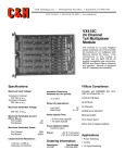
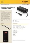
The information in this document is subject to change without notice.
Trident Robotics and Research, Inc. does not guarantee the accuracy of the information contained in this document
and makes no commitment to keep it up-to-date.
Trident Robotics and Research, Inc. makes no warranty of any kind with regard to this material, including, but not
limited to, the implied warranties of merchantability and fitness for a particular purpose.
This device is not intended for use in medical support equipment and should not be used in any application where
intermittent malfunction or failure may directly jeopardize the health or well-being of an individual or individuals.
Address comments concerning this document to:
Trident Robotics and Research, Inc.
User Documentation Department
2516 Matterhorn Drive
Wexford, PA 15090-7962
(412) 934-8348
SlotSavr is a trademark of Trident Robotics and Research, Inc.
PUMA is a trademark of Unimation, Inc.
Unimate is a registered trademark of Unimation, Inc.
Revised: November, 1993
TRC005 User's Manual
Page i
Contents
1.0 Introduction........................................................................................................... 2
1.1 General Information ................................................................................... 2
2.0 Specifications ........................................................................................................ 2
3.0 Installation............................................................................................................. 2
3.1 General Information ................................................................................... 2
3.2 IACKOUT Jumper..................................................................................... 3
3.3 Address Space Selection ............................................................................ 3
3.4 Base Address Selection .............................................................................. 4
3.5 DTACK Jumper......................................................................................... 5
3.6 Watchdog Timer ........................................................................................ 5
3.7 Connections to TRC005............................................................................. 5
4.0 Operations............................................................................................................. 6
4.1 General Information ................................................................................... 6
4.2 Reads and Writes ....................................................................................... 6
4.3 Watchdog Timer ........................................................................................ 6
4.4 Debug Option ............................................................................................ 6
5.0 Troubleshooting .................................................................................................... 7
5.1 Problem Resolution.................................................................................... 7
5.2 Technical Support ...................................................................................... 7
6.0 Schematics ............................................................................................................ 7
TRC005 User's Manual
Page 1
Trident Robotics and Research, Inc.
TRC005
VMEbus Interface Card
A Member of the SlotSavrTM Family of Control Peripherals
1.0 Introduction
1.1 General Information
The TRC005 is a member of the SlotSavrTM family of control peripherals. Its unique design
allows for the connection of multiple input/output (I/O) cards to a single slot in the host
backplane. It is a VMEbus address decoder card designed specifically for use with the TRC004
I/O card. It provides address decoding and bus buffering for up to two TRC004's. In addition, it
provides two watchdog timer circuits that automatically "open" if the respective TRC004 is not
addressed for writing every 20 milliseconds. This provides a safety feature to de-energize power
circuits in the event that the real-time control hardware or software "crashes."
The TRC004, also manufactured by Trident Robotics, is a general purpose interface board for
servo applications. It provides eight channels of buffered analog output, eight channels of analog
input, six quadrature shaft encoder channels, six bits of discrete input and six bits of opencollector discrete output. It is designed to be located physically close to the analog circuits it is
controlling, so it requires a separate bus interface card to sit on the real-time bus (VMEbus in the
case of the TRC005) and perform address decoding and bus buffering functions.
2.0 Specifications
The TRC005 is addressable in either short I/O space (16-bit address) or standard memory
space (24-bit address). No interrupt support is provided. One or two TRC004 cards can be
connected to a single TRC005 and each occupies adjacent and contiguous 32-word (64-byte)
blocks of the space. The base address of the TRC005 is fully user selectable via DIP switches.
IACKOUT is hardwired through the card.
3.0 Installation
3.1 General Information
The TRC005 is transparent from a software standpoint. There are no configuration registers
that affect its operation. All configuration is done by means of jumpers and DIP switches which
are described below. It's only purpose is to provide a base address for the memory map of the
TRC004's.
The locations of components important to the user are shown in figure 1.
NOTE: NEVER INSTALL OR REMOVE A CARD FROM A VME CHASSIS WITH POWER
APPLIED.
TRC005 User's Manual
Page 2
VME
P1
RISE
JP5B
JP5A
Hibyte
Midbyte
S2
S1
JP4
FALL
JP3
ADDR MOD
SHT/STD
JP1
JP2
U27 U26
P3
ROBOT A
U25 U24
8 8
8 8
DEBUG B
DEBUG A
D2
D4
P4
ROBOT B
J1
J2
Figure 1: Component locations
3.2 IACKOUT Jumper
IACKIN and IACKOUT are daisy chained interrupt acknowledge signals specified in the
VMEbus specification. IACKOUT is hardwired through the card to IACKIN. Therefore, it is
irrelevant whether the IACKIN/IACKOUT jumper has been removed or not from the VME
backplane (pins A21 and A22) for the particular slot into which the TRC005 is inserted. There is
no jumper on the TRC005 to configure IACKOUT.
3.3 Address Space Selection
The TRC005 can be addressed in either short (16-bit) I/O space or standard (24-bit) memory
space using supervisory or non-privileged accesses. There are a total of four different address
modifier codes that the TRC005 can respond to in the following combinations:
Address Modifier Codes Type of Access
2D only
Short supervisory I/O access
3D only
Standard supervisory data access
2D or 29
Short supervisory or short non-privileged I/O access
3D or 39
Standard supervisory or standard non-privileged data access
Selection of the address size (short or standard) is determined by the position of jumper JP2.
To select short addressing, position JP2 over the center and left pins when viewing the board with
the VME connector, P1, at the top. To select standard addressing, position JP2 over the center
and right pins when viewing the board in the same orientation. These jumper positions are
illustrated in figure 2.
TRC005 User's Manual
Page 3
JP2
JP2
Short Addressing
Standard Addressing
Figure 2: JP2 jumper positions for short and standard addressing
To select the appropriate address modifier codes, install or remove jumpers on JP1. Jumpers
on JP1 must only be installed vertically, when viewing the board with the VME connector, P1, at
the top, in positions AM2 or AM4. Figure 3 details these positions and orientations. Any other
orientation is invalid and may cause unpredictable operation. Address modifier (AM) codes are
selected according to Table 1. The default configuration will respond to AM codes 3D or 39,
standard supervisory or non-privileged data access (memory space).
JP1
JP1
AM2 Position
AM4 Position
Figure 3: Jumper positions for JP1
AM Code
2D only
3D only
2D or 29
3D or 39
Jumper AM2
OUT
OUT
IN
IN
Jumper AM4
IN
OUT
IN
OUT
Table 1: Selecting address modifier codes
3.4 Base Address Selection
The 128-byte window for the two robots can be arbitrarily located anywhere within the
chosen 16-bit or 24-bit address space by adjusting the DIP switches of S1 and S2. Switches 1
through 9 of switch block S1 select address bits A7 through A15, respectively. Switches 1
through 8 of switch block S2 select address bits A16 through A23, respectively, only when
standard accesses are selected as described in section 3.2. Sliding a switch toward the word "on"
printed on the switch block selects the "on" position which corresponds to a logic zero (0) for the
TRC005 User's Manual
Page 4
respective address bit.
The remaining address bits, A0 through A6, select the appropriate board and register. A6
selects robot A when logic zero (0) and robot B when logic one (1). A1 through A5 are decoded
by the selected TRC004 board. These bits multiplex the desired word-length register onto the
data bus as determined by the TRC004 memory map. Bit A0 is not decoded at all, therefore, ALL
ACCESSES MUST BE WORD LENGTH AND WORD ALIGNED.
NOTE: THE TRC005 ONLY RESPONDS TO WORD (16-BIT) ACCESSES.
Figure 4 shows example settings of S1 and S2 for a base address of 0xFF5100. In this
example robot A would respond to accesses in the range 0xFF5100 - 0xFF513E while robot B
would respond to accesses in the range 0xFF5140 - 0xFF517E. The debug option (switch S2-9) is
off. It is important to note that the entire address range, 0xFF5100 - 0xFF517E, is consumed
regardless of the number of TRC004 cards actually attached to the TRC005. Any word access to
this range will generate a DTACK pulse from the TRC005.
HIBYTE
MIDBYTE
9 8 7 6 5 4 3 2 1
9 8 7 6 5 4 3 2 1
ON
ON
S2
S1
= OFF = 1
= ON = 0
Figure 4: Example base address (0xFF5100)
3.5 DTACK Jumper
The DTACK jumper, JP3, belongs in position 4 and should not be moved.
3.6 Watchdog Timer
The watchdog timer requires no configuration. Its time-out interval is fixed at the factory at
between 20 and 100 milliseconds. Connections are made with a miniature phone plug to J1 for
robot A and J2 for robot B. The phone jacks connect to both contacts of an SPST relay. These
contacts are electrically isolated from the TRC005 and the TRC004. The contacts are closed
during normal operation (when the timer is constantly reset). The contacts open when write
operations stop and the timer is allowed to time-out.
The relay contacts of the watchdog timer are intended for low current operation. Under no
circumstances should the current through the relay contacts exceed 1 amp.
3.7 Connections to TRC005
A 50-conductor ribbon cable connects the TRC005 to each of its associated TRC004's. This
cable should be no longer than 3 meters. There are no other connections between the TRC004
and TRC005.
The two watchdog timers have separate miniature phone jacks. The SPST contacts of the
TRC005 User's Manual
Page 5
watchdog relay are connected to both terminals. For operation with a PUMATM robot, connect the
relay contacts in series with the arm power port. (See PUMA documentation.)
4.0 Operations
4.1 General Information
To a host computer, the TRC004 is characterized as a block of 16-bit memory locations as
described in the TRC004 User's Manual. These locations reside on 16-bit boundaries from the
BASE address. THE TRC004 DOES NOT EXAMINE ADDRESS BIT A0 (LSB) FOR
ADDRESS DECODING. Therefore, all data transfers through the TRC005 must be word size
and must be word-aligned.
The TRC005 is transparent to this operation except for the establishing of the BASE address
and the address modifier.
4.2 Reads and Writes
All reads and writes to and from the two TRC004's occur within their specified address space,
subject to the selection of BASE address and address modifier as described in section 3. All
accesses must be word size and word aligned. 8-bit and 32-bit accesses are ignored.
4.3 Watchdog Timer
Two watchdog timers are installed on the TRC005. Each timer operates independently of the
other and is reset by any write to the 32-word address space of its corresponding TRC004
channel. The timer controls a relay, the SPST contacts of which are connected to the miniature
phone jack on the card panel. If the timer is not reset at least every 20 milliseconds (this number
may range from 20 - 100 milliseconds), the timer opens the relay. This relay can switch a
maximum of 1 amp.
The LED's D2 and D4 indicate the status of the respective watchdog relays for robots A and
B. When the LED is illuminated, the relay is closed.
NOTE: WRITE ACCESSES OCCURRING WITH A PERIOD SLIGHTLY LONGER THAN
THE TIME-OUT PERIOD WILL MAKE THE LED APPEAR TO BE ILLUMINATED
WHEN, IN FACT, IT IS FLASHING AT THE ACCESS RATE.
4.4 Debug Option
A debugging aid is provided as an option to help monitor data flow to and from the TRC004
boards. This option consists only of two seven-segment LED's for each robot channel that display
hexadecimal values. The two displays latch data bits 0-3 and 8-11 for every access, read or write,
to their respective TRC004. Bits 0-3 appear on U24 for robot A and U26 for robot B. Bits 8-11
appear on U25 for robot A and U27 for robot B. It is important to note that these LED's cannot
be used to monitor general bus traffic. They only latch data within the address space of the
TRC005.
The displays can be turned on or off by switch 9 of switch block S2. When the switch is in the
ON position, the displays are on. To reduce power consumption, it is recommended that they
remain off during normal operation.
TRC005 User's Manual
Page 6
5.0 Troubleshooting
5.1 Problem Resolution
The following represent a few common errors that may prevent normal operation of the board
set. This is not an exhaustive list of problems, nor is it an exhaustive list of solutions for these
problems. Use of the debug option, if installed, can help determine if proper accesses are
occurring on the VME bus and if the proper data is being sent to the TRC004.
Problem: Board does not respond to reads or writes.
Solution: See next problem.
Problem: Bus error occurs when attempting to read or write.
Solution: 1.) DIP switches and/or jumpers are incorrectly set. See section 3.
2.) DIP switches are not fully seated in position. Flip them back and forth.
3.) Invalid access mode. Accesses must be 16 bits wide and must match the address
modifier codes selected. See section 3.
4.) DTACK jumper, JP3 or JP4, is missing.
Problem: Values read from TRC004 appear noisy.
Solution: Cable to TRC004 from P3 or P4 is too long. Cable must not exceed 3 meters.
Problem: Debug LED's (U24 - U27) are not present.
Solution: Debug option was not ordered. Call Trident Robotics to order.
Problem: Debug LED's (U24 - U27) do not illuminate.
Solution: Switch S2-9 is not on or is not fully seated in the ON position. Flip switch to ON
position or rapidly flip switch off and on.
Problem: When used with PUMA robot, arm power does not come on.
Solution: Watchdog timer has timed out or arm power port is not connected correctly. A write
to the TRC005 must occur approximately every 20 milliseconds to keep the watchdog
energized.
5.2 Technical Support
If you are not able to resolve a problem yourself, note the serial numbers and model numbers,
including any revision letters, of all Trident products involved and contact technical support at
(412) 934-8348. If this application involves a PUMA robot, also note the manufacturing date and
model number from the side of the UnimateTM controller.
6.0 Schematics
Complete schematics of the TRC005 follow.
TRC005 User's Manual
Page 7