1
VME
P1
RISE
JP5B
JP5A
Hibyte
Midbyte
S2
S1
JP4
FALL
JP3
ADDR MOD
SHT/STD
JP1
JP2
U27 U26
P3
ROBOT A
U25 U24
8 8
8 8
DEBUG B
DEBUG A
D2
D4
P4
ROBOT B
J1
J2
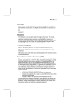
Figure 1: Component locations
3.2 IACKOUT Jumper
IACKIN and IACKOUT are daisy chained interrupt acknowledge signals specified in the
VMEbus specification. IACKOUT is hardwired through the card to IACKIN. Therefore, it is
irrelevant whether the IACKIN/IACKOUT jumper has been removed or not from the VME
backplane (pins A21 and A22) for the particular slot into which the TRC005 is inserted. There is
no jumper on the TRC005 to configure IACKOUT.
3.3 Address Space Selection
The TRC005 can be addressed in either short (16-bit) I/O space or standard (24-bit) memory
space using supervisory or non-privileged accesses. There are a total of four different address
modifier codes that the TRC005 can respond to in the following combinations:
Address Modifier Codes Type of Access
2D only
Short supervisory I/O access
3D only
Standard supervisory data access
2D or 29
Short supervisory or short non-privileged I/O access
3D or 39
Standard supervisory or standard non-privileged data access
Selection of the address size (short or standard) is determined by the position of jumper JP2.
To select short addressing, position JP2 over the center and left pins when viewing the board with
the VME connector, P1, at the top. To select standard addressing, position JP2 over the center
and right pins when viewing the board in the same orientation. These jumper positions are
illustrated in figure 2.
TRC005 User's Manual
Page 3