1
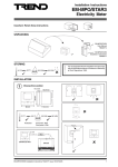
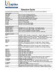
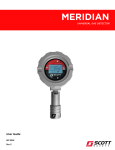
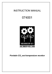
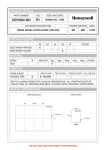
Data Sheet
CO2+T
Space and Duct CO2 Sensors
Space and Duct CO2 Sensors
Description
Features
The CO2 sensors monitor the temperature and carbon dioxide
concentration in air. Duct and wall-mounting versions employ
‘state of the art’ non-dispersive infra-red technology with a
membrane covered sample chamber resulting in stable, reliable,
and highly accurate CO2 measurements. The all-digital microprocessor based electronics facilitates easy configuration and
calibration via an RS232 port connection. Programmable linear
analogue outputs indicate temperature and CO 2 concentration
making the sensors ideal for all CO 2 based ventilation control and
monitoring applications.
•
•
•
•
•
•
•
Non-dispersive infra-red (NDIR) technology
Digital electronics - intelligent sensor
Analogue outputs 10 V or 20 mA for both CO 2 and temperature
RS232 port for configuration and calibration
24 Vac/dc supply
Links configure outputs V or I, and start point (0% or 20%)
Analogue output range and scaling programmable
Physical
lid
83 mm
(3.27”)
Duct Sensor
Space Sensor
Error LED
cover
thermistor
duct mounting
flange
probe
83 mm (3.27”) max
cover
screw
cover
120 mm (4.53”)
PG7 cable
gland knockout
220 mm (8.66”)
PG9 cable gland
knockout
88 mm (3.46”)
140 mm (5.51”)
45 mm (1.77”)
wall plate
main part
30 mm (1.18”)
21 mm (0.83”)
CO2+T Space and Duct CO2 Sensors Data Sheet TA102165 Issue 3/B 20/02/07
1
CO2+T
Data Sheet
APPLICATIONS
Carbon dioxide is acknowledged as a good indicator of occupancy
within a space. Ventilation control based on CO2 levels saves
energy. Proper ventilation also helps clear the air, reducing
floating toxins and organic compounds that hang in the air, and
the spread of common viruses and bacteria that lead to temporary
sickness and lost productivity.
Suitable applications include monitoring and controlling CO2 levels
according to indoor air quality guidelines, (e.g. ASHRAE 621989), activating a high limit alarm in CO2 usage areas, and other
CO2 monitoring applications such as greenhouses, mushroom
farms, food storage etc.
• Minimum detected ambient CO2 concentration: 270 ppm.
• Typical ambient CO2 concentrations: 350 to 450 ppm.
• National Boards of Occupational Safety and Health recognise
CO 2 concentration as an indicator of Indoor Air Quality (IAQ)
in occupied spaces; a concentration of below 1000 ppm
should be aimed for.
• ASHRAE standard for maximum CO2 concentration (adopted
as recommended maximum in most European countries):
1000 ppm.
FUNCTIONALITY
Sensors
Software
This sensor uses non-dispersive infra-red technology to sense
CO2 concentrations in ppm. Its all-digital signal processing design
enables high accuracy and output versatility. Any long term drift
is taken care of by its automatic baseline correction (ABC)
algorithm. The sensor uses a thermistor to measure ambient
temperature.
The programming of parameters, and calibration are performed
using the User Interface Programme (UIP-“Strategy”). This runs
under Windows 95, 98 or NT. Connection to a PC is made locally
via the sensor's RS232 port using the special 9 way D type
female to 5 way in line adaptor cable. The UIP, adaptor cable, and
User's Manual are supplied in the CO2/RKVT calibration kit. The
UIP software and Users Manual are also available via the Web
(see below, ORDER CODES).
Hardware
The space sensor consists of a wall mounting unit. The top cover
is removed by undoing the single cover screw and sliding it from
the unit. The main body is then separated from the wall plate by
pushing the main unit up and tilting it forwards. The wall plate has
5 mounting holes and should be screwed to the wall by a
minimum of two screws. Cables can either be brought in from
the back through the wall plate, or from the top via two knockouts
in the top cover.
top cover
cable entry slot
cable entry slot
60 mm (2.36”)
cable entry
11 mm (0.43”)
83 mm
(3.27”)
22 mm
(0.87”)
25 mm
(0.98”)
The duct sensor consists of a box and a sampling probe. The
sampling probe is mounted in the duct by drilling a 25 mm hole for
the probe, and two 4 mm holes for the screws. The probe is
screwed to the duct using the rubber gasket and the two screws
and washers provided. The duct sensor box has a lid fixed by
a plastic clip, and 4 cable gland knockouts (three PG9, one PG7).
The sensor is supplied with one PG7 gland, and one PG9 gland.
The box is fixed to the probe by firstly carefully laying the
thermistor sensor down into the probe The mechanical connection
of the box to the probe is polarised with one large notch and three
smaller notches so that the box is offered up to the probe with
the large locking projection on the probe locating into the large
notch in the box. The box is then pushed onto the probe against
the 'O' ring gasket (supplied) and twisted to lock the box in
position.
55 mm (2.17”)
Self Diagnostic Check
A full system test is executed automatically every time the power
is turned on. In addition during operation, the sensor probes are
constantly checked for failure by checking their valid dynamic
measurement ranges. All EEPROM updates, initiated by the sensor
itself, as well as by external connections, are checked by
subsequent memory read back and data comparisons. These
different system checks return error bytes to the system RAM.
The error codes listed below are shown in the UIP program
running on a PC which is connected to the RS232 port of the
sensor using the special 9 way D type female to 5 way in-line
adaptor cable. Warm up and out of range are the only bits that
are reset automatically after a return to normal state. All other
error bits have to be reset manually after return to normal by
power off and restart
00 no errors
01 Fatal Error; try restart
02 Reserved
04 Algorithm Error (wrong EEPROM configuration); try
restart, check software using UIP program
08 Output Error (error in calculation and generation of output
signals); check output connections and loads, check
status of outputs with UIP program
16 Self Diagnostic Error (may indicate need for zero
calibration or sensor replacement); Check self diagnostic
status with UIP program
32 Out Of Range Error (accompanies most other errors,
also indicates failures of sensors and inputs); check
connections of temperature and relative humidity probe,
check detailed status of measurements with UIP program
64 Memory Error (non fatal during memory operations);
check detailed settings and configuration with UIP
program.
128Warm Up State (always occurs after power up or power
failure); should disappear after 30 s, if not check power
stability)
The errors are in a binary code and can be added together so
an error code of 40 would result from a combination of Output
Error (8) and Out of Range Error (32).
Ø 25 mm (0.98”)
2
2 off Ø 4 mm (0.18”)
When any error is detected the yellow LED will flash.
CO2+T Space and Duct CO2 Sensors Data Sheet TA102165 Issue 3/B 20/02/07
Data Sheet
CO2+T
Analogue Outputs
Configuration
Both linear analogue outputs are configured by default so that
output OUT1 produces 0 to 10 V for a gas concentration of 0 to
2000 ppm, and OUT2 produces 0 to 10V for a temperature range
of 0 to +50 °C (+32 °F to +122 °F). The output signals for each
channel can be changed independently to be either 0 to 10 V or
0 to 20 mA using on board links. The start point of the output range
can be changed for both channels (not independently) using one
link to be either 0% (0 V or 0 mA), or 20 % (2 V or 4 mA).
The default configuration provides a functional sensor as
described above, however if required it may be configured using
the UIP software. This enables the two analogue outputs to
become functions of both inputs (CO2 and temperature). The
inputs can be rescaled, offset and combined as required
LED indicator
There is one yellow LED sensor which flashes after each
measurement cycle during which an error has occurred.
INSTALLATION
The sensor should be mounted in a location representative of the area to be controlled (e.g. in the controlled air space, or the return
duct). Locations with direct draft as well as badly mixed air should be avoided. (Note that a direct draft will interfere with the internal
self heating compensation and will reduce temperature measurement accuracy).To reduce risk of damage or direct exposure to
human exhalation the space sensor should be placed at least 2 metres (6’6”) above the floor.
The installation procedure consists of:
wiring sensor (outputs, power)
mounting sensor
setting links
applying power - checking yellow indicator?
setting up IQ
checking sensor operation
changing parameters (if required)
The space sensor is mounted by partially dismantling the unit and
mounting the wall plate. The main body of the sensor then clips
onto the wall plate.
The duct sensor is mounted by drilling 2 fixing holes and 1 sensor
probe hole. The sensor box is fixed to the probe by a quick twist
bayonet fixing. In duct mounting applications it is essential to
check that there is no leakage from the room environment into
the duct mounting box.
Full details are given in the CO2+T/S Space CO2 Sensor Installation Instructions TG102191 and CO2+T/D Duct CO2 Sensor Installation
Instructions TG200091.
CONNECTIONS
Wire the supply to the sensor (either 24 Vac or 24 Vdc)
Wire the output signals to the IQ controller.
C O
2
S e n s o r
G +
G 0
P T C
fu s e
+ ~
-
P o w e r s u p p ly
S y s te m
O U T 1
A n a lo g u e o u tp u t 1
O U T 2
A n a lo g u e o u tp u t 2
IN 1
C
C
S y s te m
g ro u n d *
Note that the sensor signal ground is connected to the
power supply return via a PTC fuse. Ensure the same
ground is used for the IQ controller. For IQs with a 24 V
(ac or dc) supply check that the IQ can accept grounded
inputs; if not, either suply the sensor from the IQ auxiliary
suply, or use an isloated supply
2 4 V
a c o r d c
s u p p ly
g ro u n d
IN 2
IQ
C
L in k IQ fo r
v o lta g e ( V )
if s e t to
d e fa u lts
* s y s te m g r o u n d v ia P T C
( p o s itiv e te m p e r a tu r e c o e ffic ie n t) fu s e
Note that with the default settings, OUT1 is the CO2
output and OUT2 is the temperature output, but this may
be changed by configuring using the UIP program.
The IQ controller sensor type needs to be configured to match
the sensor output range and proportional band. See specification
for sensor type settings needed for a sensor with default settings.
DISPOSAL
WEEE Directive :
At the end of their useful life the packaging,
and product should be disposed of by a suitable
recycling centre.
Do not dispose of with normal household waste. Do not burn.
MAINTENANCE
Shipment and poor handling may result in a change of zero point
which should be checked after installation is completed.
The recommended calibration interval is 5 years.
Calibration can be performed using the UIP User Interface
Programme. This is described in the User Interface Program
User's Manual.
The space sensor should be cleaned periodically using a damp
cloth. Gently wipe external surfaces clean.
Check the duct sensor box and the sample tube for dust and dirt
when inspecting the ventilation system. If necessary, blow them
clean.
CO2+T Space and Duct CO2 Sensors Data Sheet TA102165 Issue 3/B 20/02/07
3
CO2+T
Data Sheet
ORDER CODES
CO2+T/S
CO2+T/D
CO2/RKVT
CO2/ZERO
CO2/VALVE
CO2/RK
CO2/CAL
CO2 Space Sensor
CO2 Duct Sensor
Calibration kit for units post 04/97, containing User Interface Program (UIP - also named 'Strategy'), the UIP User's
Manual, and the 9 way D type female to 5 way in-line adapter cable. This enables both calibration and configuration.
Zero CO2 test gas cylinder. Required for calibration of sensor when using calibration kit (both pre and post 04/97).
Valve for gas cylinder including 3 mm tube (both pre and post 04/97)
Calibration Kit pre 04/97 containing User Interface Program, adapter cable, plastic gas tube and rubber blanket.
1700 ppm CO2 test gas cylinder. Required for calibration of sensor when using calibration kit (pre 04/97 only).
Note that the UIP program and user's manual are available free-issue from the following website www.senseair.com.
SPECIFICATIONS
Measurement
Temperature
Operating principle
Measurement Range
Accuracy
CO2
Operating principle
Gas sampling mode
Measurement range
Thermistor
:0 to 50 °C (32 °F to 122 °F) (default), 20 to +60 °C (-4 °F to 140 °F) (maximum
configurable)
:±0.5 °C (±0.9 °F)
:Non-dispersive infra red (NDIR)
:Diffusion
:0 to 2000 ppm (default), 0 to 3000 ppm
(maximum configurable), numerical
resolution 1 ppm
Accuracy
:±1% measurement range, ±5 % of reading
(within ±10 °C, ±18 °F, calibration temp)
Long term drift
:ABC (automatic baseline correction)
target 400 ppm, period 8 days
Annual zero drift
:<±0.3% measurement range
Response time
:2 min diffusion (20 s with tube
connection at 0.1 l/min)
Warm up time
:<= 1 min (<=15 min at full spec.)
Pressure dependence :+ 1.58 % reading per kPa deviation from
100 kPa
Calibration adjustments:zero and span via RS232 port
Calibration procedure :Automated with User Interface Program
(UIP)
Calibration interval
:5 years
Sensor Life Expectancy :>15 years
Electrical
Power Requirement
Power Consumption
Analog Outputs
Resolution
D/A conversion
Response Time
Protection
Data Interface
IQ scaling
Defaults
:24 Vac/Vdc ±20%, 50 or 60 Hz
:<=3 Watts
:2 off, 0 to 10 Vdc (by default) Rout<100Ω,
Rload>5kΩ (Can be changed to 4 to 20 mA
by linking, Rload <500Ω - see Functionality
section above)
:10 bits (10mV/0.016 mA)
:accuracy ±2% of measurement, voltage
±50 mV, current ±0.3 mA
:2s
:PTC fuse (auto reset), short circuit safe
:RS232 serial port
:for sensor with default settings
:OUT1, 0 to 10 V for 0 to 2000 ppm, CO2
:OUT2, 0 to 10 V for 0 to 50 °C (+32 °F to
+122 °F), Temp
If the output configurations have been modified from the defaults,
the IQ scaling settings will be different. See Sensor Scaling
Reference Card for details on how to calculate the settings.
The input channels must be set up for analogue voltage, V, and
correct scaling. It is recommended to use SET (software tool)
for the setting of the sensor type module. For all IQ2 series
controllers with firmware v 2.1 or greater, or IQ3 seres controllers,
the following SET Unique Sensor References should be used:
humidity:
CO2 V
temperature: Temp V 0+50 (°C)
Temp V+32+122 F (°F)
Alternatively enter the values manually as defined in the tables
below with scaling mode 5 (characterise). For all other controllers
see the Sensor Scaling Reference Card, TB100521A.
CO2 output (default OUT1)
Use sensor type scaling mode 5, characterise with input type set
to 0 (volts, V) and the table below.
Input type 0 (volts V)
Y
System Accuracy
(including controller)
:±23 ppm ±5% reading
(0 to 2000 ppm, 20 to 25 °C)
E
Exponent
4
U
Upper
2000
0
L
Lower
P
Points
2
n
In
On
1
0
0
2
10
2000
Temperature output (default OUT2)
Use sensor type scaling mode 5, characterise with input type set
to 0 (volts, V) and the table below.
System Accuracy
(including controller)
:±0.6 °C ±2% reading
(0 to +50 °C)
Mechanical
°C
°F
Y
Input type
E
Exponent
U
Upper
50
L
Lower
0
P
Points
n
In
1
0
0
32
2
10
50
122
3
122
32
2
On
Mounting
Space :Removable wall plate for 2 off 4 mm
screws
Duct :25 mm (0.83”) probe hole with two screw
fixing to duct; bayonet fixing of probe to
sensor box (screws and gasket
provided)
Dimensions
Space :83 x 120 x 30 mm (3.27 x 4.53 x 3.27”)
Duct :83 x 140 x 45 mm (308 (12.13”) including
probe) (3.27 x 5.51 x 1.77”)
Weight
Space :185 g (6.5 oz)
Duct : 640 g (22.5 oz)
Connections
:(main block) Screw terminals, 1.5 mm2
(16 AWG) max
RS232 connection
:5 pin, 2.54 mm pitch , slide connector
Environmental
Storage Temp.
Operating Temp.
Humidity
Compliance
:-20 °C to +70 °C (-4 °F to 158 °F)
:0 °C to +50 °C (32 °F to 122 °F)
:0 to 95 %RH non-condensing
:EMC Directive 89/336/EEC
Indicators
Yellow LED
:Flashes when error is detected by
self-diagnostic routine.
Manufactured for and on behalf of the Environmental and Combustion Controls Division of Honeywell Technologies Sàrl, Ecublens, Route
du Bois 37,Switzerland by its Authorized Representative.
Trend Control Systems Limited reserves the right to revise this publication from time to time and make changes to the content
hereof without obligation to notify any person of such revisions or changes.
Trend Control Systems Limited
P.O. Box 34, Horsham, West Sussex, RH12 2YF, UK. Tel:+44 (0)1403 211888 Fax:+44 (0)1403 241608 www.trend-controls.com
Trend Control Systems USA
6670 185th Avenue NE, Redmond, Washington 98052, USA. Tel: (425)897-3900, Fax: (425)869-8445 www.trend-controls.com
4
CO2+T Space and Duct CO2 Sensors Data Sheet TA102165 Issue 3/B 20/02/07