1
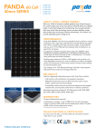
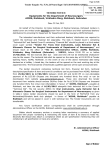
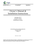
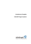
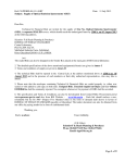
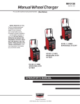
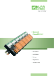
Display Panel Manual CONTENTS Author: R Williams Issue: 4/B Date: 27/6/00 Part No: 90-1505 Copyright: Trend Control Systems Ltd Horsham, W. Sussex All rights reserved. This manual contains proprietary information which is protected by copyright. No part of this manual may be reproduced, transcribed, stored in a retrieval system, translated into any language or computer language, or transmitted in any form whatsoever without the prior consent of the publisher. For information contact: Trend Control Systems Ltd P.O. Box 34 Horsham W. Sussex RH12 2YF Tel:+44 (0)1403 211888 Fax:+44 (0) 1403 241608 www.trend-controls.com NOTICE: Trend Control Systems Ltd makes no representations or warranties of any kind whatsoever with respect to the contents hereof and specifically disclaims any implied warranties of merchantability or fitness for any particular purpose. Trend Control Systems Ltd shall not be liable for any errors contained herein or for incidental or consequential damages in connection with the furnishing, performance or use of this material. Trend Control Systems Ltd reserves the right to revise this publication from time to time and make changes in the content hereof without obligation to notify any person of such revisions or changes. Printed in the United Kingdom. ii Display Panel Manual Issue 4/B 27/6/00 CONTENTS 1 1.1 1.2 1.3 1.4 1.5 2 2.1 2.2 2.3 2.4 2.5 3 3.1 3.2 3.3 3.4 3.5 3.6 3.7 3.8 3.9 INTRODUCTION The Display Panel About This Manual Types of Display Panel 1.3.1 Membrane Types 1.3.2 Display Panel Types 1.3.3 Integral Display Panel 1.3.4 Display Panel in Front of Panel 1.3.5 Hand Held Display Panel Compatibility Product Codes INSTALLATION Hand Held Display Panel Integral Mounting Display Panel Front Panel Mounting Display Panel Remote Display Support Installation of Remote Display Panels. 2.5.1 Location 2.5.2 Connect to Controller 2.5.3 Test Operation 2.5.4 Adjust Viewing Angle 2.5.5 Configure Controller 2.5.6 Set up Programmable Buttons USING THE DISPLAY PANEL General Principles of Operation The Display Page 3.3.1 Display Format 3.3.2 Data Presentation 3.3.3 Display Page Selection 3.3.4 IQ2xx Series Controllers (and IQ151+) - Display Page sequence 3.3.5 IQ1xx Series Controllers (except IQ151+) - Display Page sequence Adjusting a Value Programming the Soft Buttons PIN/Password Levels Display Page - terminology used in examples Status Display Page Time Display Page Display Panel Manual Issue 4/B 27/6/00 iii CONTENTS 3.10 3.11 3.12 3.13 3.14 3.15 3.16 3.17 3.18 3.19 3.20 3.21 Sensors Display Page (IQ2xx Series & IQ151+) Digital Inputs Display Page (IQ2xx Series & IQ151+) Knob Display Page 3.12.1 Knob adjustment of Analogue Node 3.12.2 Knob adjustment of Module Parameter Id Switches Display Page Driver Display Page Zone Display Page Optimum Start/Stop Display Page Calendar Display Page Alarm History Display Page Dialler Page (IQ22x/ADL controllers only) Inputs Display Page (IQ1xx Series Controllers except IQ151+) Internal Display Page (IQ1xx Series Controllers except IQ151+) INDEX iv Display Panel Manual Issue 4/B 27/6/00 INTRODUCTION 1 INTRODUCTION 1.1 The Display Panel The Display Panel (sometimes referred to as the 2-line Display to distinguish it from the Network Display Panel) enables the user to view and adjust selected parameters of an IQ controller. This is achieved by four direction buttons and a 2 row, x 40 character, LED backlit, liquid crystal display. In addition four preprogrammable buttons make commonly changed values available by single button selection. It provides all the facilities necessary for the operation of a stand alone building control system. The Display Panel may be: an integral part of a Controller an externally mounted option to a Controller or a portable unit that may be connected to a Controller, wherever and whenever required. The Display Panel has no intelligence of its own. The program for its operation is resident in the currently connected controller. Power and communications are connected over the multi-way cable between the display panel and controller. It may not be used to communicate with controllers other than the one to which it is directly connected. 1.2 About This Manual This manual provides information on the installation and use of the Display Panel. It does not contain the detailed information on configuring or installing the controller. Labels and other values used by the Display Panel must be set up using a Trend supervisor or engineers tool. Configuration instructions are contained in the IQ Configuration Reference Manual, 90-1533. Information contained in this manual is related to IQ2xx Firmware versions 1,2 (IQ1xx Firmware versions 5, 6, 7, and 8). Information is provided in 3 sections: Section 1 Section 2 Section 3 Introduction, Display Panel Types, and Compatibility Installation Operation Display Panel Manual Issue 4/B 27/6/00 page 1-1 INTRODUCTION 1.3 Types of Display Panel 1.3.1 Membrane Types There are two versions of display panel membranes. The first (M1) is used on all current display panel products including integal fitting into IQ2xx series controllers. The older membrane (M2) was used on old display panel products but is the only panel that can be integrally fitted into old IQ1xx series controllers. display D P A B + C ) * D soft buttons arrow buttons Membrane version M1 • • • • 1.3.2 soft buttons Membrane version M2 LED backlit, Liquid Crystal Display, 2 rows x 40 characters 4 arrow buttons 4 user-programmable soft buttons A,B,C & D all keys have tactile feedback Display Panel Types Display Panel Types There are two basic types with the new membrane (M1), DP2 and DP (sometimes referred to as 2DP). They both use LED backlit, LCD (liquid crystal) displays. DP2 :This display panel may be mounted in the cover of an IQ2xx controller. It cannot be used outside a controller. It is identified by a 34 way (IDC type) connector (normally via an attached ribbon cable). DP :This display panel may be mounted outside a IQ2xx controller (if the controller has an ‘RDS’, Remote Display Support, interface board fitted). It may also be used external to IQ1xx controllers. It is identified by a 25 way male ‘D’ type connector. page 1-2 Display Panel Manual Issue 4/B 27/6/00 INTRODUCTION 1.3.2 Display Panel Types (continued) There was also an earlier display panel type with the old membrane (M2) which was used either externally or fitted in the cover of an IQ1xx controller. The external version had a 25 Way male ‘D’ type connector and the integral version had a 26 Way (IDC type) connector. Integral versions were supplied with a 26 Way to 26 Way (IDC) adaptor ribbon cable or a 26 Way IDC to 25 Way ‘D’ type male adaptor cable (for IQ9xe, IQ8xe). All of these display panel types may be fitted in the cover of an IQ controller, fitted in the front of a panel, or provided as a hand held unit which can be plugged into the controller. 1.3.3 Integral Display Panel An IQ22x, IQ241, or IQ242 controller may be purchased with an integral display panel (DP2) fitted in the cover. The display panel thus requires no installation, and will operate directly the controller is powered. These controllers may also be retrofitted with a display panel by purchasing the the appropriate retrofit kit which includes a cable, and installation instructions and for the IQ22x, a replacement cover (fitted with a display panel), and for the IQ241 or IQ242, a display panel with nylon pillars for fitting into the cover. Note that a display panel may reduce the controller’s available 24 Vdc supply current by 30 mA. 1.3.4 Display Panel in Front of Panel D P A B C D A display panel (DP) may be remotely mounted away from the controller, for example on a panel door. This is done by using the front panel mounting kit (FPK). Alternatively the standard 600 x 600 mm enclosure may be purchased with the display panel already fitted in the door (ENCLS/FP). Standard enclosure with display panel fitted (ENCLS/FP) A 3 m cable is supplied with both of these options. If fitting a display panel to a controller, note that it may reduce available 24 Vdc supply current by 30 mA. The kit (FPK) provides 4 screws for mounting on a panel door up to 5 mm thick; for a thicker door the installer should provide longer 4 mm screws. Display Panel Manual Issue 4/B 27/6/00 page 1-3 INTRODUCTION 1.3.4 Display Panel in Front of Panel (continued) Detail of display panel fixed to door using fixing kit (FPK) The backplate may be used as a template to cut the holes in the panel. 5 holes Ø 4.5 display panel 4 screws 107 55 58 15 33 35 39 gasket 169 Note that the display panel is not suitable for mounting outside a building. It can be used on an IQ22x, IQ241, IQ242, or IQ250 controller if it has been fitted with an ‘RDS’ interface. It can also be used with an IQ204 or any IQ1xx series controller except an IQ7x, IQ9x, IQ9x+, (although it may be used with an IQ9xe). 1.3.5 Hand Held Display Panel The display panel (DP) is also provided as a hand held unit (HDP). This allows the user to plug the display panel into a controller either permanently or on a temporary basis. It is useful as a portable tool for locally monitoring and adjusting a number of controllers. A 1 m cable is supplied with the HDP. When plugging a display panel into a controller note that it may reduce available 24 Vdc supply current by 30 mA. It can be used on an IQ22x, IQ241, IQ242, or IQ250 controller if it has been fitted with an ‘RDS’ interface. It can also be used with an IQ204 or any IQ1xx series controller except an IQ70, IQ90, IQ90+, (although it can be used with an IQ9xe). 1 6 1 page 1-4 2 3 4 5 6 7 8 9 1 0 1 1 1 7 1 2 1 8 V 1 3 1 9 L A N 2 0 T X 1 4 1 5 R X L A N 2 4 V Display Panel Manual Issue 4/B 27/6/00 INTRODUCTION 1.4 Compatibility Series IQ2xx IQ1xx Controllers Integral Display Panel Remote Display Panel (FP, FPK, HDP) M1/DP2 M2 M1/DP IQ21x û û û M2 û IQ22x ü û ü* ü* IQ241, 242 ü û ü* ü* IQ246 û û û û IQ250 û û ü* ü* IQ251 û û û û IQ204 û û ü ü IQ7x û û û û IQ9x, 9x+, 10x û û û û IQ9xe, 8xe û ü** ü ü IQ100+ û ü ü ü IQ111, 111+, 131,131+, 151, 151+ û ü ü ü IQ104/OEM û û ü ü Key M1 M1/DP2 M1/DP M2 * ** :new membrane :new membrane with DP2 type display :new membrane with DP type display :display panel with old membrane :These controllers need to have /RDS option fitted :These controllers need special 24 W to 24 W IDC cable Display Panel Manual Issue 4/B 27/6/00 page 1-5 INTRODUCTION 1.5 Product Codes IQ2xx/DP/ :IQ2xx (IQ22x, IQ241, IQ242) controller with display panel fitted in cover. KIT/DP2 :Kit for retro-fitting display panel into IQ241 or IQ242, complete with display panel, nylon pillars, attached ribbon cable, and installation instructions. COVER/DP/IQ22x :Kit for replacing cover of IQ22x with cover pre-fitted with display panel complete with attached ribbon cable and installation instructions. FPK :Kit for fitting display panel to the front of a panel complete with display panel, gasket, fixing screws, 3 m cable, and installation instructions. ENCLS/FP :600 x 600 x 210 mm cabinet pre-fitted with display panel complete with 3 m cable, fixing screws, and ENCLS installation instructions. The ENCLS cabinet is pre-drilled to fit a range of IQ controllers. HDP :Hand held display panel complete with 1 m cable. Note that all the above display panel products are supplied with a display panel manual. KIT/2XX/RDS CABLE/58-0935 CABLE/58-0836 page 1-6 :Kit for fitting the remote display support (RDS) interface into an IQ2xx controller (IQ22x, IQ241, IQ242, or IQ250) to enable a remote display panel (front of panel, or hand held) to be connected to the controller, complete with attached ribbon cable, fixing screws, and installation instructions. :1 m length, 25 way ‘D’ type male to 25 way ‘D’ type female cable for connecting display panel to controller. :3 m length, 25 way ‘D’ type male to 25 way ‘D’ type female cable for connecting display panel to controller. Display Panel Manual Issue 4/B 27/6/00 INSTALLATION 2 INSTALLATION The display panel comes in 3 versions: Hand held (HDP) Integral mounted (/DP or retrofit, COVER/DP/IQ22x, KIT/DP2) Front panel mounting (FPK or ENCLS/FP) 2.1 Hand Held Display Panel The hand held version (HDP) is plugged into the controller via the adaptor cable provided (CABLE/58-0935, 1 m). Its installation is described below (section 2.5). In order to connect the HDP to IQ2xx Series Controllers (IQ22x, IQ241/242, IQ250) the controller must have the /RDS option fitted by using KIT/2xx/RDS (see section 2.4). (The IQ204 does not need the /RDS option to connect to the HDP). hand held unit (HDP) Connector to IQ Controller (signal and power) 168 mm 144 mm 105 mm , 2 ) * + , rear 190 mm 32 mm viewing angle adjustment Display Panel Manual Issue 4/B 27/6/00 page 2-1 INSTALLATION 2.2 Integral Mounting Display Panel The controllers (IQ22x, IQ241/242) may be ordered with the display panel fitted in the cover (/DP/ option). The display panel may be fitted into the IQ241/242 at a later date by using the KIT/DP2 product. This process is described in: KIT/DP2 Retrofit Display Panel Kit Installation Instructions (IQ241/242), TG103173. The IQ22x cover may be exchanged for a cover incorporating the display panel by using the COVER/DP/IQ22x product. The installation process is described in: COVER/DP/IQ22x IQ22x Replacement Cover with Display Panel Installation Instructions, TG200140. 2.3 Front Panel Mounting Display Panel This can either be a kit for fitting the display panel in a panel door (FPK), or a cabinet pre-fitted with the display panel (ENCLS/FP). The installation of the FPK is described in: FPK Front Panel Kit (2-Line Display Panel) Installation Instructions, TG200179. The ENCLS/FP comes pre-installed, so there are no separate display panel installation instructions. Both of the above panels come with adaptor cable 3 m CABLE/58-0836 which need to be connected to the IQ Controller and tested as described below (section 2.5). In order to connect the FP, FPK to IQ2xx Series Controllers (IQ22x, IQ241/242, IQ250) the controller must have the /RDS option fitting by using KIT/2xx/RDS (see section 2.4) (The IQ204 does not need the /RDS option to connect to FP or FPK). page 2-2 Display Panel Manual Issue 4/B 27/6/00 INSTALLATION 2.4 Remote Display Support This interface board can be fitted to an IQ22x, IQ241/242, IQ250 to enable a remote display panel to be connected to the controller. Its installation process is described in KIT/2xx/RDS Remote Display Support Kit Installation Instructions TG103128. 2.5 Installation of Remote Display Panels. 2.5.1 Location Ambient Limits The display panel specification is 0 to 50 °C and 0 to 90 %RH (non-condensing), however IQ Controllers are normally rated at 0 to 45 °C, and the display panel will generally be in the same environment as the IQ Controller. IP Ratings HDP ENCLS/FP FPK :IP30 :IP54 (if panel properly closed) :membrane rated at IP54. When mounted in a panel, total rating depends on rating of panel. Note that the display panel is not suitable for mounting outside a building. Display Panel Manual Issue 4/B 27/6/00 page 2-3 INSTALLATION 2.5.2 Connect to Controller HDP (rear of unit) (DP board used in FP, FPK, shown dashed) 25 W D Female screened cable CABLE/58-0935 (1 m) or CABLE/58-0836 (3 m) 25 W D Male DP Connector IQ Controller The details of connecting to the controllers are given in their installation instructions: IQ22x Installation Instructions - Options, TG200009 IQ24x Installation Instructions - Options, TG200146 IQ25x Installation Instructions, TG103483 IQ204 Installation Instructions - Options, TG200154 Note that use of cables or connections other than those specified by Trend may result in failure to comply with EMC requirements. The cables must be screened. Note that plugging a display panel into a controller may reduce available 24 Vdc supply current by 30 mA. 2.5.3 Test Operation Note that if the display panel is connected to a controller that is already powered, then the display should be reset by pressing one of the programmable soft-buttons labelled A-D. Test display panel operation by making selections as described in Section 3. page 2-4 Display Panel Manual Issue 4/B 27/6/00 INSTALLATION 2.5.4 Adjust Viewing Angle The viewing angle should be adjusted if the display panel appears to be faint. The adjustment is made by turning a small slot head screw located behind and to the right of the display panel connector when viewed for the rear. 2.5.5 Configure Controller IQ IQ or Controller configuration is explained in IQ Configuration Manual 90-1533 and 822+/Toolbox Manual 90-1129. The following parameters may be set up using the controller configuration mode to customise the display panel (see Section 3). Passwords Password levels on Knobs and Switches Range of Knobs Labels and Units of Sensors, Knobs, Switches, Drivers, Zones Language Note that if some of an item type’s labels are set up, on those items of that type with preset labels will be seen on the display panel but if no labels of an item type are set up, all items of that type can be seen. Display Panel Manual Issue 4/B 27/6/00 page 2-5 INSTALLATION 2.5.6 Set up Programmable Buttons , 2 ) * programmable buttons + , The setting of the programmable buttons is explained in sections 3-5. page 2-6 Display Panel Manual Issue 4/B 27/6/00 USING THE DISPLAY PANEL 3 USING THE DISPLAY PANEL This section of the manual provides general operating instructions, the principles of operation, and an example of each Display Panel page. 3.1 General The Display Panel is used for: Monitoring: Adjustments: Controller temperatures, setpoints, hours-run, and plant status Controller setpoints, controller overrides, time and calendar functions, and reset hours-run and counters. Adjustments may be password protected, in which case a valid Personal Identification Number (PIN) must be entered before the operation can go ahead. (See Section 3.6). Before the Display Panel can be used the following controller items must be set up (if required for future monitoring or adjustment by the Display Panel) using configuration mode: Passwords Password Levels on Knobs and Switches Range of Knobs Labels and Units for Sensors, Knobs, Switches, Drivers and Zones. The language of the Display Panel may be changed by altering the display panel language selection in the controller configuration mode address module; it cannot be changed from the Display Panel itself. The languages that may be selected are: English, Spanish, Finnish, Swedish, Norwegian, Danish, German, Italian, Portuguese, and French. Changing the Display Panel language also changes the language of transmitted text alarms. Note: For any Display Panel page, labelling of items will have the following effect: - where no item has a label - all items will be displayed. - where one or more items have labels - only the items with labels will be displayed. Display Panel Manual Issue 4/B 27/6/00 page 3-1 USING THE DISPLAY PANEL 3.2 Principles of Operation There are two versions of the Display Panel Membrane: Version 1 and Version 2, both are shown below. display , 2 up ) * + + ) * , down programmable right left buttons Membrane version M1 left right programmable buttons Membrane version M2 The Display Panel is divided into the display and the keypad: The display consists of two rows of text and data. Each row is 40 characters long and displays text labels and variable data in different fields. The keypad comprises two parts: The group of four arrow buttons designated left, right, up and down allow access to monitor information and make changes.The left and right buttons are used to position the cursor on the displayed values which may be adjusted. The up and down buttons are used to increase and decrease the value at the cursor position. If a button is held down, this will cause the button action to be repeated at half second intervals. The four programmable buttons labelled A, B, C, and D can be programmed to view any four specified display pages. This allows direct access to particular locations without having to manually step through the normal display sequence. For example they could be set up as follows: A = Occupation Setpoint B = Non-occupation Setpoint C = Occupation Override D = Alarm 20 page 3-2 Knob 1 Knob 2 Switch 1 the last recorded alarm Display Panel Manual Issue 4/B 27/6/00 USING THE DISPLAY PANEL 3.3 The Display Page 3.3.1 Display Format Of the twelve display pages, nine are formatted in a similar manner, and present the following data: Item type Item number Item label Data specific to that item Each display page will be covered in detail below, and will be described using an example and a list of the display field options. All fields on a display page will be refreshed every 5 seconds. 3.3.2 Data Presentation Numbers are of three different types; integers, real numbers, and times. Integers (item numbers, communications addresses etc) are displayed as three characters with leading zeros not displayed. e.g. 1, 22, 230. Real numbers (sensor values, knob values etc.) are displayed in as six characters with leading leading zeros not displayed. e.g. 433, 6355.28. The decimal point position is determined by the exponent value of a sensor and there is always one decimal place allowed for knobs in a range from -999.9 to 9999.9. Times are shown as four digits separated by a colon in HH:MM format (i.e. 24 hour notation, hour hour : minute minute e.g. 08:24, 12:30). 3.3.3 Display Page Selection When first powered up, the display cursor appears at the top left-hand corner of the STATUS PAGE. (If the display panel is connected to a controller which is already powered e.g. using a Hand Held DP, then the display should be reset by pressing one of the programmable buttons labelled A to D). From this position the cursor can be moved between the data areas which may be changed using the left and right arrow buttons. Pressing the left or right button several times moves the cursor back to its original position at the top left-hand corner of the display i.e. the cursor ‘wraps around’. Display Panel Manual Issue 4/B 27/6/00 page 3-3 USING THE DISPLAY PANEL 3.3 The Display Page (continued) Only when the cursor is in the top left-hand position of the page display can the next display page be called. This is done by pressing the up/down buttons. Starting from the STATUS PAGE and pressing the up button, the sequence of pages that appears in the display is shown below. Starting from the STATUS PAGE and pressing the down button, the sequence of pages is reversed (i.e. Status Page - (Dialler page) - Alarm Page etc.). 3.3.4 IQ2xx Series Controllers (and IQ151+) - Display Page sequence STATUS PAGE Controller address, issue no. TIME PAGE Controller time/date, seasonal change dates SENSOR PAGE Sensor and controller calculated values DIGITAL INPUT PAGE Status signals KNOB PAGE User adjusted values - e.g. Setpoints SWITCH PAGE User - manual switch actions DRIVER PAGE Controller output signal status TIME ZONE PAGE On/Off time periods 5 zones OPTIMUM START/STOP System calculated heating/cooling times CALENDAR PAGE Holiday settings ALARM PAGE Shows up to 20 recorded alarms DIALLER PAGE Autodialling Status (IQ22x/ADL only) 3.3.5 IQ1xx Series Controllers (except IQ151+) - Display Page sequence Inputs and Internals display the output of the Sensor module on the Display Panel. Therefore, if a Universal Input is used as a digital input, the input/ internal will only display its state at the Display Panel if the appropriate sensor module is made a digital input sensor. STATUS PAGE TIME PAGE INPUT PAGE INTERNAL PAGE KNOB PAGE SWITCH PAGE DRIVER PAGE page 3-4 Controller address, issue no. Controller time/date, seasonal change dates Sensor measurements and status signals Controller calculated values User adjusted values - e.g. Setpoints User - manual switch actions Controller output signal status Display Panel Manual Issue 4/B 27/6/00 USING THE DISPLAY PANEL 3.3 The Display Page (continued) TIME ZONE PAGE OPTIMUM START/STOP CALENDAR PAGE ALARM PAGE 3.4 On/Off time periods 5 zones System calculated heating/cooling times Holiday settings Shows up to 20 recorded alarms Adjusting a Value To change a value (e.g a knob): (1) Select the required field using the right button. This will position the blink (square) cursor on the right hand digit of any adjustable numeric field. If large changes are required use the left button to backtrack to the required digit. (2) Use the up button to increment the entry, and the down button to decrement the entry. The cursor will change from blink to underline whilst a value is being changed. Five seconds after the up or down button is released the blinking cursor returns indicating that the new value has been accepted by the controller. If the cursor is moved from the value then the value is immediately entered into the controller. If the value is password protected then the display will change to a page requesting the entry of a valid PIN, ‘Enter your PIN ****’, the cursor being positioned on the first digit of the PIN. Set up the first digit using the up or down button, followed by the right button to select the next digit. Once all four digits have been entered, pressing the right button again will cause the controller to verify the PIN. If a valid password has been entered, the item display page will return with the cursor now set to an underline. The value can then be changed by the up/down button as appropriate. Once a valid password is entered, all items at or below that password level may be altered. The password will time-out two minutes after the last key was pressed. If an invalid password is entered, the Display Panel prompts ‘Edit Inhibited’. No changes can then be made. Display Panel Manual Issue 4/B 27/6/00 page 3-5 USING THE DISPLAY PANEL 3.5 Programming the Soft Buttons The buttons labelled A, B, C, and D provide quick access to four pre-programmed items which are frequently monitored or changed e.g. setpoint adjustments and time control, etc. The buttons are programmed as follows: (1) Select the required display and position the cursor on the value which will be required to be changed. (2) Hold down the required programmable button, initially the display will change to the previously programmed selection. After approximately five seconds the display will revert to the new selection unless the entry of a PIN is required. In this case the request ‘Enter your PIN ****’ will appear and a valid PIN must be entered before the new selection is accepted, otherwise the Display Panel prompts “Edit Inhibited” and the display will change to the previously programmed selection. Subsequently, short presses of this button will select the newly programmed page with the cursor set in the position defined. 3.6 PIN/Password Levels When changing values in a controller the following parameters have fixed PIN/ Password levels: Knobs Switches Addresses Time and Date Seasonal Time changes Zone times (Current week) Zone times (Standard week) Holiday date Holiday time Reprogram soft keys 0 - 100 as set during configuration 0 - 100 as set during configuration 90 50 50 30 50 50 70 90 When an attempt is made to change a protected parameter, the user must enter a four digit PIN which has previously been set up in the controller to have a priority level above that for the selected item as shown above. If the PIN is valid, the change can be made, but if not valid, the change will be inhibited. Once a valid password is entered, it will enable changes for items equal to or below its priority level. It will time-out two minutes after the last button is pressed. page 3-6 Display Panel Manual Issue 4/B 27/6/00 USING THE DISPLAY PANEL 3.7 Display Page - terminology used in examples An example of each type of display page is included in sections 3.8 to 3.20. Displayed information is described using the following terms: Row - may be 1 or 2 and relates to the upper or lower row of the display. Field - is the reference number of a section of a display page. Length - is the the maximum number of characters that can exist in a data field. Monitor only - indicates that the data in this field is a variable value, which cannot be changed by the operator. Fixed Label - indicates a label which is determined by the program, which cannot be changed. Display Panel Manual Issue 4/B 27/6/00 page 3-7 USING THE DISPLAY PANEL 3.8 Status Display Page The Status Display page, shown below, shows the identity of the currently connected controller, and allows modification of the controller address or the destination address for alarms. STATUS FRIDGE PACK 2 Address 20 DATA OK ALARM 1 on LAN 0 Text off IQ220 2.0 Row Field 1 1 2 'Status' Label 6 15 Change to select new display page 3 4 5 'Address' address Dynamic Data State 7 3 5 6 7 'Alarm' Alarm Address 5 3 8 9 'on LAN' LAN address 6 Fixed label Address of controller. *Flashes DATA OK (when working correctly), or DATA ERROR (in case of HELP alarm). Monitor only. Fixed label Node address of target supervisor to which alarms are to be sent. 0 = no reporting. 2 = direct connected supervisor interface. Fixed label LAN number to which alarms are to be sent. 0 = local LAN or auto-dialled via ANC+ on local LAN 10 Text alarms 8 Toggle between Text alarms 'Text On' and normal alarms 'Text Off' selection. 11 12 'IQxxx' Version 5 3 Fixed label 2 * Description Length 3 Comments 15 characters controller identifier - can be changed in configuration mode Software (firmware) issue in the format X.X. Monitor only. DATA OK - non alarm condition DATA ERROR - an alarm condition generated when a HELP alarm exists within the controller. (See Section 3.18) page 3-8 Display Panel Manual Issue 4/B 27/6/00 USING THE DISPLAY PANEL 3.9 Time Display Page The Time Display page, shown below, allows the operator to monitor or change the current time and date, or the Seasonal Time change data. Time 15:36 TUE 17JAN88 on by 1 hour on 21APR Row Field 1 1 2 'Time' Time 4 5 3 Day of week 3 4 Date 7 5 6 'on by' change by 5 1 7 8 'hour on' Date 7 5 9 10 'back on' Date 7 5 2 Description Length back on 21OCT Comments Change to select new display page Time in format HH:MM. Can be changed if valid password entered. Three letter code for the day of the week. Can be changed if valid password is entered. Date in format dd.mmm.yy. Where dd is the day date (2 digits), mmm is the month (3 letters ) and yy is the year (2 digits). Can be changed if valid password is entered. Fixed label Amount of seasonal time change in hours. Can be changed if valid password is entered. Fixed label Date in format dd.mmm. Where dd is the day date (2 digits), and mmm is the month (3 letters). Can be changed if valid password is entered. Fixed label Date in form dd.mmm. Where dd is the day date (2 digits), and mmm is the month (3 letters). Can be changed if valid password is entered. Display Panel Manual Issue 4/B 27/6/00 page 3-9 USING THE DISPLAY PANEL 3.10 Sensors Display Page (IQ2xx Series & IQ151+) Note that IQ1xx Series Controllers (except IQ151+) have Inputs and Internal pages instead of Sensors and Digital Inputs. External sensors measure plant levels external to the system (e.g. temperature and humidity). Internal sensors are values derived within the controller. Sens Row 1 2 Field 1 2 3 4 5 6 7 page 3-10 1 OUTSIDE AIR SENSOR FAIL Description Sens Sensor No Label Values Units Alarm Int/Ext Length 4 2 20 6 4 11 8 14.1 DEGC External Comments Change to select item Change to select sensor No. Edit in configuration mode. Monitor only Edit in configuration mode. Flashing display of Alarm condition. Whether sensor is INTERNAL or EXTERNAL. Can be changed in configuration mode. Display Panel Manual Issue 4/B 27/6/00 USING THE DISPLAY PANEL 3.11 Digital Inputs Display Page (IQ2xx Series & IQ151+) Note that IQ1xx Series Controllers (except IQ151+) have Inputs and Internal pages instead of Sensor and Digital Inputs. External Digital inputs are status inputs (i.e. ON or OFF) coming from outside the controller, whereas internal digital inputs are derived internally. Digin 10 Boiler 1 Row 1 2 Field 1 2 3 4 5 6 Description Digin Digin No Label Values Alarm Internal ON External Length 5 2 20 3 10 8 Display Panel Manual Issue 4/B 27/6/00 Comments Change to select item Change to select Digin No. Edit in configuration mode. Monitor only Flashing display of Alarm condition. Whether digin is INTERNAL or EXTERNAL. Can be changed in configuration mode page 3-11 USING THE DISPLAY PANEL 3.12 Knob Display Page 3.12.1 Knob adjustment of Analogue Node A Knob is a value that can be adjusted by the operator. It can either be an adjustment to an analogue node e.g. a setpoint or a limit, or it can be an adjustment of a module parameter e.g. loop gain. KNOB Row 1 2 1 OCCUPIED SETPOINT 20.5 DEGC MINIMUM 15.0 MAXIMUM 35.0 Field 1 2 3 4 Description 'Knob' Knob No. Label Value Length 6 2 20 6 Comments Change to select new display page Change to select knob number Edit in configuration mode Value can be changed if valid password is entered. Edit in configuration mode Fixed label 5 6 Units 'Minimum' 4 7 7 min Value 6 The lower limit of the range over which the knob may be adjusted. This can be edited in configuration mode. 8 'Maximum' 7 Fixed label 9 max Value 6 The upper limit of the range over which the knob may be adjusted. This can be edited in configuration mode. page 3-12 Display Panel Manual Issue 4/B 27/6/00 USING THE DISPLAY PANEL 3.12 Knob Display Page (continued) 3.12.2 Knob adjustment of Module Parameter Id KNOB 21 FLOW TEMP ALARM 25.0 DEGC S19H H alarm 25.0 (+/-32.767) Where the knob has been configured to change a module parameter the display page changes as follows: Row 1 is unchanged Row 2 provides the following fields Row 2 Field 6 Description parameter Id string 7 *Configuration display 8 *Configuration Range Length Comments 4 This is the normal configuration mode identity for the parameter to be changed. This is the normal text used to identify the parameter and its value in configuration mode. - This is the normal permitted range of the adjustment in configuration mode. *These two items come from the configuration mode display for the module affected and confirm the change in the module itself. They will not be displayed if the controller is in configuration mode, (e.g. another user is configuring the controller). In this mode the value cannot be displayed and the legend ‘Utility Busy’ will be shown. Display Panel Manual Issue 4/B 27/6/00 page 3-13 USING THE DISPLAY PANEL 3.13 Switches Display Page A switch is a status (i.e. ON or OFF) that can be changed by the operator (e.g. Summer/Winter switch). Switch Row 1 Field 1 2 3 4 page 3-14 1 MANUAL OVERRIDE Description 'Switch' Switch No. Label State Length 6 2 20 3 ON Comments Change to select new display page Change to select switch number Edit in configuration mode Current state - ON or OFF can be changed if a valid password is entered. Display Panel Manual Issue 4/B 27/6/00 USING THE DISPLAY PANEL 3.14 Driver Display Page Driver 1 Radiant Heater INVERTED O/P 1 O/P 2 ON 32.2% READBAK A Driver is the output module of the controller. Six types of Driver modules exist as follows: Driver type digital output analogue output time proportional raise/lower binary switch time proportional and override Row 1 2 Field 1 2 3 4 Description 'Driver' Driver No. Label Value Current State of Driver (Row 2 - Field 6) Inverted Inverted Inverted Raise, Lower, Static Inverted Inverted, Override Length 6 2 20 6 5 '%' 1 6 State 8 7 'O/P1' 6 8 State 3 9 'O/P2' 3 10 State 3 Display Panel Manual Issue 4/B 27/6/00 Comments Change to selec new display page Change to select dirver number Edit in configuration mode Monitor only. Value of input, ON/OFF for digital driver. Fixed label Current state of driver. Will be empty or display 'Inverted, Raise, Lower, Static or Override' as shown in the list above. Fixed label. Only shown if in-phase output chanel is set up. In-phase output channel state (ON/OFF) or level for analogue. (0-100%) For TP+0 100% = override 70% = off 40% = on Fixed label only shown if anit-phase output channel set up. Anti-phase output channel state (ON/OFF) page 3-15 USING THE DISPLAY PANEL 3.14 Driver Display Page (continued) Row 2 Field 11 * Description Driver Length Comments 7 This display will alternate between ALARM and either READBACK or SERVICE if either of the alarms are present. The display will cycle between ALARM, READBACK, and SERVICE, if both alarms are present. If no alarm will be blank. READBACK ALARM - failure of the Plant to execute function, detected by readback data, from the plant. SERVICE ALARM - generated when maintenance interval has been exceeded. Normally pre-programmed maintenance interval for driven pumps and other ancillary equipment. page 3-16 Display Panel Manual Issue 4/B 27/6/00 USING THE DISPLAY PANEL 3.15 Zone Display Page A time zone is an area of the building or its plant which operates a common time schedule. It defines the building occupation start and stop times. ZONE 2 MEAT PREP- AREA NEXT THR 07:30to12:30 13:30to18:00 24:00to24:00 Row 1 2 Field 1 2 3 4 Description 'Zone' Zone number Label Week type Length 4 1 20 6 5 6 Day of Week Period 1 start 4 5 7 8 'to' Period 1 stop 5 5 9 Period 2 start 5 10 11 'to' Period 2 stop 5 5 12 Period 3 start 5 13 14 'to' Period 3 stop 5 5 Comments Change to select new display page Change to select zone number Edit in configuration 'Next' refers to current week. 'Every' refers to standard week. Toggle with up and down keys. Change to select day of week Change to select new Period 1 start time. Password protected. Fixed label Change to select new Period 1 stop time. Password protected. Change to select new Period 2 start time. Password protected. Fixed label Change to select new Period 2 stop time. Password protected. Change to select new Period 3 start time. Password protected. Fixed label Change to select new Period 3 stop time. Password protected. Note: Immediately after selection of this display page, the day displayed will be the current day in the current week. Note: If a period’s start and stop times are equal (e.g. 24:00 to 24:00), it is a period of non-occupation. Note: A change made to the Every week (standard week) will also update the corresponding day in the Next week (current week) at the next midnight (see IQ Configuration Manual ‘Zone Times’). Display Panel Manual Issue 4/B 27/6/00 page 3-17 USING THE DISPLAY PANEL 3.16 Optimum Start/Stop Display Page Optimum start/stop applies to a particular time zone. It calculates the optimum start so that the zone reaches occupation temperature by the zone occupation start time. OSS ZONE 2 VESTRY LAST START 07:31 NEXT STOP 12:13 HEATING Row 1 Field 1 2 3 Description 'OSS Zone' Zone number Label 2 4 Start time label 10 Next/Last start. 'Next Start' between end of occupation and optiumum start, otherwise, 'Last Start'. Monitor only. 5 Start time 5 Time in HH:MM. Monitor only. 6 Stop time label 9 Next/Last start. 'Next Stop' between end of occupation and optiumum start, otherwise, 'Last Stop'. Monitor only. 7 8 Stop time OSS state 5 7 Time in HH:MM. Monitor only. page 3-18 Length Comments 8 Change to select new display page 1 Change to select OSS zone number 20 Edit in configuration mode Current OSS Zone state Heating/Cooling/OFF. Monitor only. Display Panel Manual Issue 4/B 27/6/00 USING THE DISPLAY PANEL 3.17 Calendar Display Page The calendar page, shown below, defines up to 20 periods during which special operating times are used (e.g. holidays). On each of these dates, each zone’s times are defined. Calendr 5 Next 25Dec-27Dec Zone 1 Spec 1 07:30to11:30 24:00to24:00 24:00to24:00 Row 1 Field 1 2 3 Description Calendar Holiday No Holiday status Length Comments 7 Change to select new display page 2 Change to select holiday number 4 Status can be Next/Free/Each. Next: means the holiday will appear on the next occurrence of that date, then automatically becomes Free status. 4 Start Date 5 5 Stop Date 5 6 7 'Zone' Zone number 4 1 8 Occupation type 6 Display Panel Manual Issue 4/B 27/6/00 Free: means holiday will not occur. Each: means holiday will occur each year on the specified date. Can be changed if valid password is entered. Select day by number, then month as a three letter label by stepping through. Select day by number, then month as a three letter label by stepping through. Fixed label Change to see/set-up times for that zone on holiday selected. Can be changed if valid password is entered. Alternatives are:Normal Occupation, Unoccupied or Spec (Special) 1 to 5. Normal means time zones are unaffected by holiday dates. Unocc means zone is unoccupied on the holiday date. Spec 1 to 5 means that one of five special patterns of occupation times may be applied to the holiday date. Note: if changes are made to a special day, the changes will be effective wherever that special day's times are used. page 3-19 USING THE DISPLAY PANEL 3.17 Row 2 Calendar Display Page (continued) Field 8 Description Period 1 start Length Comments 5 Change to select new period 1 start time. Password protected. 9 10 'to' Period 1 stop 5 5 Fixed label 11 Period 2 start 5 Change to select new Period 2 start time. Password protected. 12 13 'to Period 2 stop 5 5 Fixed label 14 Period 3 start 5 Change to select new Period 3 start time. Password protected. 15 16 'to Period 3 stop 5 5 Fixed label Change to select new Period 1 stop time. Password protected. Change to select new Period 2 stop time. Password protected. Change to select new Period 3 stop time. Password protected. Note that no occupation times are shown if the occupation type is Normal Occupation or Unocc. page 3-20 Display Panel Manual Issue 4/B 27/6/00 USING THE DISPLAY PANEL 3.18 Alarm History Display Page Alarm History is a record of the 20 most recent alarms in chronological sequence. Where alarm 20 is the most recent, alarm 19 preceeds alarm 20 and so on. The display provides time, date, and alarm type information. The label of alarm type is displayed in the language configured for the Display Panel ALARM 3 SENSOR 12 BOILER FLUE TEMP CLEAR HIGH ALARM 17:27 THR 14AUG88 Row 1 2 Field 1 2 Description 'Alarm' Alarm Record Length Comments 5 Change to select new display page 2 Change to select alarm record 3 4 5 6 No Item type Item number Item Label 'Clear' 6 2 20 5 7 8 9 Alarm Time of Alarm Day of Week 16 5 3 10 Date 7 Type of item in alarm, monitor only. Number of item in alarm, monitor only. Label of item in alarm, monitor only. Label present if clear alarm, monitor only. Label of alarm type, monitor only. Time alarm occurred, monitor only. Day of Week (3 letters) i.e. Mon-Sun, only. Date of alarm. dd mmm yy. Where dd is the day date (2 digits), mmm is the month (3 letters), and yy is the year (2 digits). Note that when the operator has selected a specific alarm for display and another alarm occurs, then the same alarm remains displayed but the item number will be seen to change provided that the alarm buffer is not full. Display defaults to most recent alarm (no. 20). Display Panel Manual Issue 4/B 27/6/00 page 3-21 USING THE DISPLAY PANEL 3.18 Alarm History Display Page (continued) List of Alarms. (English) Equivalent alarm code DIGIN ON DIGIN OFF HIGH VALUE LOW VALUE SENSOR FAIL INPUT ERROR PV FAIL DEVIATION READBACK SERVICE RESTART DATA ERROR PIA FAULT CLOCK WRONG RAM FAULT S’WARE FAIL DART FAULT EPROM FAULT CLOCK WRONG CLOCK WRONG DI = 1 DI = 0 HIGH LOW OUTL READ PVFL SDEV SDGT MINT CONL HELP FPIA FRTC FRAM FSWR FDRT FPRM FTKA FTKP General alarm Self Test Number 1 2 3 4 5 6 7 8 9 10 Alarms The following is a brief description of each of the alarm types that may appear on the Alarm History page. DIGIN ON (DI=1), DIGIN OFF (DI=0) Digital Input state differs from required state. HIGH VALUE an alarm generated when the scaled value received from the sensor exceeds the high limit. LOW VALUE an alarm generated when the scaled value received from the sensor is less than the low limit. SENSOR FAIL an alarm generated when the measured value received from the sensor exceeds the normal maximum or minimum values defined by the sensor type. page 3-22 Display Panel Manual Issue 4/B 27/6/00 USING THE DISPLAY PANEL 3.18 Alarm History Display Page (continued) INPUT ERROR an alarm generated when the measured value received from the sensor is outside the range that can be handled by the controller input circuitry. PV FAIL Process Variable Fail, generated whenever input information required for a control loop has failed, resulting in the Alarm Fail action being taken. DEVIATION Deviation Alarm, generated whenever the difference between the sensor value and the setpoint (deviation) is greater than the deviation limit. READBACK Readback Alarm, generated whenever driver output readback check does not confirm driver output actions. SERVICE Maintanance Interval expired alarm, generated by control strategy. RESTART alarm is generated at power up or if the system is restarted, when the data file information has been checked correctly. DATA ERROR alarm is generated under conditions of data file corruption on power up or if the system has restarted and thereafter whenever an operator communicates in normal supervisor mode (not configuration mode). CLOCK WRONG Failed Real Time Clock this alarm is generated whenever the alarm condition is found; if the condition remains, the alarm is repeated at one hour intervals. PIA FAULT, RAM FAULT, S’WARE FAULT, DART FAULT and EPROM FAULT these alarms cause a CONL to be generated by restarting the controller program. If the alarm condition is still present after the CONL then the alarm is recorded. These alarms are often due to corruption of a working register by electrical noise, and can be cleared automatically by the outstation resetting itself. Thus they may be ignored unless their frequency interferes with control. CLOCK WRONG (FTKA) Failed Time Keeper Advice is generated (IQ90s only) when the controller unsuccessfully requests time and date synchronisation after power up or at midnight. If the controller is not connected to a system, or does not receive regular time and date synchronisation then this alarm will be generated at 24 hour intervals at approximately 00:10 hours. CLOCK WRONG (FTKP) Failed Time Keeper, this alarm is generated (IQ 90s only) after the FTKA. Display Panel Manual Issue 4/B 27/6/00 page 3-23 USING THE DISPLAY PANEL 3.19 Dialler Page (IQ22x/ADL controllers only) The Dialler page shows the status of the ADL (Autodialling Lite) component of the IQ22x/ADL controller. It is very useful while commissioning the /ADL controller autodial connection. DIALLER Tel No: Row 1 Field 1 2 2 3 4 Idle 1 Description 'Dialler' Status 'Tel No:' Number Length 7 21 11 29 Comments Change to select item Current status of dialler: 'Local PC mode' 'Looking for Modem' Idle' 'No dial tone' 'Local modem fault' 'Dialling' 'No answer far site' 'Link-Fail' 'Security Fail' 'Connected' 'Local modem ringing' Fixed label Telephone number The status descriptions are as follows: Local PC mode: Appears when modem disconnected from back of IQ. Looking for Modem: Transitory while confirming presence of modem. Idle: Quiescent state with modem connected to back of IQ. No dial tone: Unable to dial as local telephone connection missing. Local modem fault: The local modem has not replied in time (timeout, has an error, or is busy). Dialling: Dialling out to far site. No answer far site: Has failed to pick up carrier from far site. Link-Fail: Incompatible peer (doesn’t understand protocol), or protocol timeout. Security Fail: Mismatch of autodialling passwords between the two sites. Connected: Connected successfully to far site. Local modem ringing: Incoming call. The Number field shows the telephone number used when dialling out, or the number of an incoming call as long as the number is set up as own telephone number in the incoming call originator (e.g. TMN). page 3-24 Display Panel Manual Issue 4/B 27/6/00 USING THE DISPLAY PANEL 3.20 Inputs Display Page (IQ1xx Series Controllers except IQ151+) Note that IQ1xx Series Controllers (except IQ151+) have Inputs and Internal pages instead of Sensors and Digital Inputs. The inputs display page, shown below, shows the condition of a universal input channel; the displayed value may be either a sensor reading or a plant status (on or off). The type of displayed value depends on the configuration of the sensor module. I/P 11 GROUND FLOOR FOYER LOW VALUE Row Field 1 1 2 3 4 I/P Sensor No. Label Value 4 2 18 6 5 6 Units Alarm 4 10 7 Int/Ext 8 2 * Description 19.5 DEGC External Length Comments Change to select new display page Change to select Sensor No. Edit in Configuration mode Monitor only. Digital Input = status. Analogue Input = real number value. Edit in Configuration mode *Display of alarm condition HIGH VALUE, LOW VALUE, SENSOR FAIL, INPUT ERROR or DIGIN STATE alternating with ALARM. Whether sensor is 'internal' or 'external' can be changed in Configuration mode. See Section 3.18 for explanation of alarms Display Panel Manual Issue 4/B 27/6/00 page 3-25 USING THE DISPLAY PANEL 3.21 Internal Display Page (IQ1xx Series Controllers except IQ151+) Note that IQ1xx Series Controllers (except IQ151+) have Inputs and Internal pages instead of Sensors and Digital Inputs. The Internal Display page, shown below, shows the condition of internal universal inputs (i.e one whose source is within the controller), the display will be either a value for an internal sensor or a status (on or off) for an internal digital input. INT 17 HEATING DEMAND HIGH VALUE Row Field 1 1 2 3 4 'Int' Internal No. Label Value 3 2 20 6 5 6 Units Alarm 4 10 7 'Internal' 8 2 Description 99.0% Internal Length Comments Change to select new display page Change to select internal no. Edit in configuration mode Monitor only. Digital Input = Status. Analogue Input = real number value. Edit in configuration mode Display of alarm condition HIGH VALUE, LOW VALUE, SENSOR FAIL, INPUT ERROR or DIGIN STATE alternating with ALARM. Fixed label See section 3.18 for explanation of alarms. page 3-26 Display Panel Manual Issue 4/B 27/6/00 INDEX page number page number A ADL .............................................................. 3-24 alarm history ................................................ 3-21 alarms page ............................................ 3-4, 3-5 arrow buttons ......................................... 1-2, 3-2 autodial ......................................................... 3-24 Autodialling Lite .......................................... 3-24 C calendar page .............................. 3-4, 3-5, 3-19 change a value ................................................ 3-5 clock wrong ........................................ 3-22, 3-23 communications .............................................. 1-1 configuration ................................................... 1-1 Connected .................................................... 3-24 D dart fault ............................................. 3-22, 3-23 data error ................................... 3-8, 3-22, 3-23 data ok ............................................................. 3-8 deviation ............................................. 3-22, 3-23 Dialler page .................................................. 3-24 Dialling: ....................................................... 3-24 digin off ........................................................ 3-22 digin on ........................................................ 3-22 digital inputs page .......................................... 3-4 direction keys .................................................. 1-1 display ............................................................. 3-2 display pages ................................................... 3-3 driver ............................................................ 3-15 driver page ...................................................... 3-4 E edit inhibited ................................................... 3-5 Enter your PIN ................................................ 3-5 Eprom fault ........................................ 3-22, 3-23 F field ................................................................. 3-7 fixed label ....................................................... 3-7 H help .................................................................. 3-8 high value ..................................................... 3-22 I Idle ................................................................ 3-24 input error .......................................... 3-22, 3-23 inputs display page ...................................... 3-25 inputs page ...................................................... 3-4 integers ............................................................ 3-3 internal display page .................................... 3-26 internal sensor page ........................................ 3-4 K keypad ............................................................. 3-2 knob .............................................................. 3-12 knobs page ...................................................... 3-4 L labels ............................................................... 1-1 language .......................................................... 3-1 length ............................................................... 3-7 Link-Fail ....................................................... 3-24 liquid crystal display ...................................... 1-1 Local modem fault ....................................... 3-24 Local modem ringing .................................. 3-24 Local PC mode ............................................. 3-24 Looking for Modem ..................................... 3-24 low value ...................................................... 3-22 M manual ............................................................. 1-1 membranes ............................................. 1-2, 3-2 monitor only .................................................... 3-7 N No answer far site ........................................ 3-24 No dial tone .................................................. 3-24 Number ......................................................... 3-24 numbers ........................................................... 3-3 O optimum start/stop ...................... 3-4, 3-5, 3-18 P page sequence ................................................. 3-4 password .......................................................... 3-1 password levels ............................................... 3-6 PIA fault ............................................. 3-22, 3-23 PIN .......................................................... 3-1, 3-5 power ............................................................... 1-1 prgarammable buttons .................................... 1-1 PV fail ................................................ 3-22, 3-23 Display Panel User Manual Issue 4/B 27/6/00 page I-1 INDEX INDEX page number page number R RAM fault ......................................... 3-22, 3-23 readback ............................................ 3-22, 3-23 readback alarm ............................................. 3-16 real numbers ................................................... 3-3 restart ................................................. 3-22, 3-23 row .................................................................. 3-7 S Security Fail ................................................. 3-24 sensor fail ..................................................... 3-22 sensor page ..................................................... 3-4 service ............................................... 3-22, 3-23 service alarm ................................................ 3-16 status display .................................................. 3-8 status page ...................................................... 3-3 s'ware fail .......................................... 3-22, 3-23 switch ........................................................... 3-14 switches page ................................................. 3-4 T telephone number ........................................ 3-24 time display page ........................................... 3-9 time page ........................................................ 3-4 time zone ...................................................... 3-17 time zone page ....................................... 3-4, 3-5 times ............................................................... 3-3 page I-2 Display Panel User Manual Issue 4/B 27/6/00 INDEX page number page number Display Panel User Manual Issue 4/B 27/6/00 page I-3 INDEX page number page I-4 page number Display Panel User Manual Issue 4/B 27/6/00 INDEX page number page number Display Panel User Manual Issue 4/B 27/6/00 page I-5 Trend Control Systems Ltd PO Box 34 Horsham West Sussex RH12 2YF Tel:+44 (0)1403 211888 Fax:+44 (0)1403 241608 www.trend-controls.com