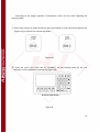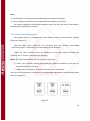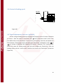
1
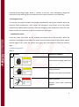
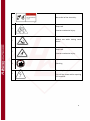
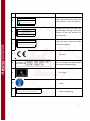
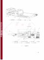
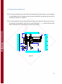
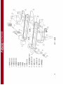
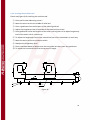
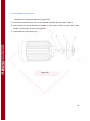
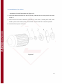
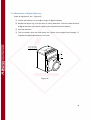
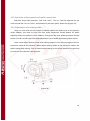
OPERATION MANUAL DOUBLE END TENONER WINTER RMD 6025A WARNING! The operator must thoroughly read this manual before operation. Keep this manual for future reference. Henrik Winter Holztechnik GmbH Druckereistr. 8 04159 Leipzig Tel: +49 (0)341/ 4619021 Fax: +49 (0)341/4618358 Funk: +49 (0)171/2820443 Em@il: [email protected] Internet: www.winter-holztechnik.de Table of contents 1. Safety ................................................................................................................................................... 3 2. Operational requirements of machine tool ...................................................................................... 10 3. Main purpose and feature of machine tool ...................................................................................... 12 4. Brief introduction of machine tool and main technical parameters ................................................. 13 6. Packing,Portage and installation of machine tool ............................................................................. 20 7. Machine tool adjustment .................................................................................................................. 20 8. Test run of machine tool ................................................................................................................... 40 9. Lubrication and maintenance............................................................................................................ 42 10. General troubles and trouble-shooting methods ........................................................................... 45 11. List of generally replaced standard parts ........................................................................................ 47 12. Function introductions of control panel.......................................................................................... 50 13. Electrical control principle ............................................................................................................... 59 14. Function and installed location of limit switches ............................................................................ 67 15.Operation manual for text display ................................................................................................... 68 2 1. Safety 1.1 General rules of safety ① Do not operate the machine before reading earnestly throught and fully understand the operation manual. The person who operates the machine must be very familiar with the adjusting contents, adjusting procedures and safety rules. ② To make proficient with specialized trainning before operating. ③ Please pay attention to the warning symbols on the machine and abide by the rules. ④ To avoid wrapping in working, workers should have their hair and sleeves bound. No loose coat, gloves and jewelry allowed while working. ⑤ Unrelated person is not allowed to stay around the running machines. ⑥ Do not stand in front of the infeed and outfeed directions to avoid unexpected injury from the rebound and spring of workpieces. ⑦ Do not raise the feeding device while processing the logs, or else the workpieces might be loosened and do harm to human and machine. ⑧ Do not take away any of the protected covers while processing. ⑨ Do not clean the chips while the machine is running, for fear that dangers might cause. ⑩ Hands are not allowed to touch the feeding belts, tooth parts of chain wheels or feeding part between feeding belt and pressure belt while running, checking or cleaning the machine. ⑪ Do not stand between the two feeding belts while narrowing them. ⑫ Daily check of the safety devices before machine starts is necessary, to eliminate hidden troubles. ⑬ Please make sure that the power is off and the machine is completely stopped befor adjusting, matain the machine and installed cutter blocks. ⑭ The maintenance and maintain of machine tools shall be done termly by qualified personnels, and the work of power system can only be done by qualified electricians. ⑮ Protected gloves are needed while installing or changing cutter blocks to prevent harming from sharp edge of knives. ⑯ Safeguards for eyes and ears are needed while working. (Noises of machine tool is no higher than 85dB) ⑰ Ensure the neatness and roominess of working locality. Any of the impediments would be effected on operation,and hidden troubles lurking. 3 ⑱ Top and bottom, left and right spindles cannot be exchanged or wrongly installed, otherwise cutter blocks might fly off from spindles while running at high velocity, serious aftereffects would follow. ⑲ Termly check the wear and tear of electrical cables to dispose troubles in time if any. ⑳ Power must be off while romoving and checking the electricity ○,21 the circuit breaker provided by end user for this machine shall have a RCD with minimum setting, which can not affect normal operation. ensure that guards and other safety devices necessary for machine operation are in position, in good working order and properly maintained ○,22 Test 2 (Fault loop impedance verification and suitability of the associated overcurrent protective device) according to clause 18.2.2 of EN 60204-1:2006 shall be performed after the final installation. Safety device of machine tool In order to make sure the safety for both operator and equipment,there are some saftety device for the machine tool ○,1 Linkage safety protective doors When open the switch of the safety door,spindles will stop automatically and the cover can be open after 60 seconds. DO NOT REMOVE the safety device、the limited switch of the cover and other switch in order to keep them effective and running in normal condition. When Open the cover to chek the device (at this moment the machine stop running and cannot start), operator must confirm that the selective swith turns to “test” position. DO NOT change the condition randomly. ○,2 Limit switch for avoiding over thickness,over width and over length. The working thickness is over the setting range will touch the limit switch of the head of pressure belt. When the working width is over the setting range ,then it will touch the limit switch of the cover to let the machine stop. There are two limit switches between the 4 max.and min.working length. When it reaches to the min. and max.working length,the machine will stop working. Do not remove the limit switch to make it runs effectively. ○,3 Emergency stop It’s necessary to contact and warn the people around Before starting the machine. When the machine shows malfunction, press either one emergency stop button to let the whole machine stop. When need to operate, reset the emergency stop button,then press the reset button to start the connector so that the machine can work again. ○,4 Safety line switch There are safety line switch on the outfeed and infeed side of the machine. When the machine is working,press the safety line switch to let the whole machine stop. When need to operate again, firstly reset the switch, then press the reset button to start the machine again. 1.3 Warning symbols Table 1 No. Symbols Meaning of Symbols 1 Cutter blocks rotating, watch out! Safety protector 2 Runners must wear ear protector. Safety protector 3 Runners must wear protective goggles. 5 4 Be careful of the electricity. Keep safe 5 Caution machanical injury. 6 Watch out while closing cover doors. Keep safe 7 Caution machanical injury. 8 Earthing Electricity here! 9 Cut off the power while repairing the machine. 6 No. Symbols Meaning of Symbols ATTEN TIO N ! 10 Open switchboard only when the main switch is in the “0” position. OPEN SW ITCHBOAR D ONLY W HEN THE M AIN SW ITCH IS IN THE "" 0 POSITIO N RMF10 ATTEN TIO N! 11 FEED CAN ON LY W O R K AFTER ALL SHAFTS H AVE STAR TED UP TO R EPO SIT TH E R ESET BU TTO N BEFO R E O PER ATIO N W H EN FIR ST TIM E TO U SE RMF13 ATTEN TIO N ! 12 TH E O U TER CO VER CAN O N LY BE O PEN ED AFTER TH E SAFETY IN D ICATO R TU R N S O N Feeding will work only after the spindle begin running. Press reset button to start the machine for the first time Open the cover when the safety indicator is lighted RMF 14 13 CE Label Do not change the speed when the machine stop working 14 15 Air origin 16 17 Hook Pay attention to extra strong spring when dismantlement. Extra strong spring 7 Safety Instructions 18 Use operation manual and safety instruction when installing、operating or maintaining 19 1.4 Correct use of machine tool ① The processing range of workpieces only limit to the data of technical parameters. Do not use if the data overruns. ② Do not process the timber with nail or concrete. ③ The user must abide by making saws and milling heads (EN847-1) to configure cutters and set the speed for the chief shaft. Cutters with oversized diameters would cause unwarrantable oscillation in high velocity which is not measure up with the safety requirment. To use oversized and overweighted cutters may not only damage the equipments but also cause serious injures to personnels. The cutters must be tested by balancing, the lopsided cutters will bring damage to the equipments by exquisite oscillation and noise. ④ When the width of the workpiece is wider than 200mm, the second cut-off saw should be set as a hogger (self-provided) so as to turn the unwanted timbers into dust in case of effecting milling cutters. ⑤ Check the locking state of cutter blocks before operating the machine. Let the machine run with nothing for at least 5 minutes to inspect running state, to get rid of obstructions in time. 8 ⑥ Before feeding, the unused spindles shall be moved back to the position where cannot touch the workpieces. ⑦ Lay the timber onto the infeed table and push hardly to the guiding fence one by one. ⑧Only if custommer require , before leaving factory, the scoring saw and cut-off saw would be equipped according to the feeding direction, vertical milling saw would be equipped according to the anti-direction of feeding (indicate the rotation direction). If change rotation direction to process, must exchange the motors of saw spindles between left and right ,as well as milling spindles between left and right, if not, gland nuts will self-loosen , it will be very dangerous . ⑨ The cross section acreage of cables must tally with the requirement of chief current of the machine. Screw the tie-in of cables which is provided with the machine, other wires and lines must meet each other by number. The earthing wires must be ensured to be valid and credible. Make sure the power is off before opening the electric box. ⑩ Do not change speed when the machine is stopped, in case of causing damage to the machine. ⑾ Press emergency stop to examine and repair when trouble comes out. ⑿ Let the machine run with nothing to clean up the chips after processing 9 2. Operational requirements of machine tool 2.1 Environment required for machine tool ① Ambient temperature:5℃~40℃. ② Relative humidity: 30%~95%. ③ Height above sea level of machine use: max. 1000m. ④ Transportation and storage temperature: –25~55℃. ⑤ Do not use in the explosion situation 2.2 Power supply, Pneumatic power, Dust collecting and Lubrication ①Power supply Three-phase alternating current, Frequency 50±1Hz, Voltage 380±10%V, total motor power 30.5kw. ②Dust collecting Wind speed must be 30 – 34 m/s, ten dust-intakes of ID (Inner Diameter)Φ116mm. Wind costs about 9000m³/h 。 ③Lubrication Using all of high temperature lubrication above 120ºC, Ca-based Grease ZG-3 ,ZG-0, engine oil N46. 10 2.3 Sound inquiry For a sound power level LWA =76.3dB(measured value ) Associated uncertainty K=2dB Measured in accordance with EN ISO 3744:1995 The figures quoted are emission levels and are not necessarily safe working levels. Whilst there is a correlation between the emission and exposure levels, this cannot be used reliably to determine whether or not further precautions are required. Factors that influence the actual level of exposure of the work-force include the characteristics of the work room, the other sources of noise etc.i.e. the number of machines and other adjacent processes. Also the permissible exposure level can vary from country to country. This information, however, will enable the machine to make a better evaluation of the hazard and risk. 11 3. Main purpose and feature of machine tool Combining the functions of sawing together with milling, this kind of machine fits most of purposes. It is specialized applying for multi-working, such as locating, fixing size by truncation , cutting, angle-truncate, tenoning and milling the plane and so on. This machine tool processes max. length of 3000mm and processes two sides of wood synchronously, also processes the wider sizes parts such as door or window frames, so these kinds of machine tool are favorable using in compound floor, door and window frames, real wood furniture and so on. Some examples please see (Figure 1) Main Feature: (1) Feeding chain belt adopts high precision casting, the chain boards have precision supporting and guiding on the two sides and the vertical position. It can reduce the noise and wear, running smoothly and can keep precise synchronous after long time using. The feeding adopts stepless variable to feed which has strong suitability and increase the production efficiency. (2) The working surface of feeding chain belt and “⊥”type pressure belt adopts good quality rubber material, which has high adhesion and reliable position located. (3) The relative velocity between pressure belt and feeding chain belt can be adjusted by differential case. The speed of pressure belt can be faster or slower than the feeding speed so that it can insure the pressing power is enough no matter you use the front or rear position of the guides. This design can fit for processing different working size of timeber. (4) Rotation speed of milling head 7500r/min,for special require will design according to the client inquiry,can be 6000 r/min。 (5) Each spindle has individual completely sliding board structure, it will interfere 12 when you use vertical,horizontal or rotation direction adjustment. It can adjust the status and position of spindle easily. (6) The machine deploy sealed、silencer cover to prevent sawdust, reduce noice and improve the working place environment. (7) Machine with light and nice structure。 4. Brief introduction of machine tool and main technical parameters 4.1 Brief introduction of machine tool Components of this machine: lathe bed, scoring saw device, cut-off saw device, milling cutter device, feeding belt device, pressure belt device, main transmission device, active rack moving device, fixing fence, solid pole, gear case, cover, eletrical control and other assistant device, please see figure 2. The main configuration: ① Lathe bed: adopts rigid jointing, and 55 degrees of coattail guide for machining. The left side of lathe stand combines the fixed rack when the right side fixes the base of main transmission. Both sides of the stand have adjusting screws and supporting pads, which equals the supporting and levels the horizontal of the lathe bed ② Scoring saw device: The saw holder is installed onto the solid pole, it’s builded to a double slide configuration by vertical slide, horizontal slide and rotator. Rotate the adjusting screw of corresponding slide to move the saw blade up or down, left or right and so as the angle adjusting. The saw blades can be installed directly onto the motor spindle when the inner diameter of the saw blade is φ25.4mm. For saw blades with inner diameter of φ40mm, some additional rings are required. And for shortest workpieces (250mm), not only the additional rings but also some special clamping nuts are required. ③ Cut-off saw device: Same as scoring saw divice but the motor spindle can be installed at one time with grooving saw and cut-of saw by adding some rings in the middle. ④ Milling cutter device: The cutter holder is installed onto the solid pole, it’s configured to be a double slide configuration. Relative to the workpieces, the milling cutter can also be moved up or down, left or right and so as the angle adjusting. 13 ⑤ Feeding belt device: Adopts double chain belt for synchronous continuous feeding. The active chain wheel drives chain belt on the guide rail while feeding. On each square of the chain belt there is wearable supporting composing the datum plane. Also there is a spring fence on every four squares of the chian belt, these spring fences of both chain belts can be set to synchronization to be an oriented-fence of workpieces. When the spring fence is needless, press and rotate it so as to hide tit under the supporting board. ⑥ Pressure belt device: This device is composed of case, driving and passive belt wheels, Ttype pressure belt and groups of pressure wheels. The pressure belt is installed onto the coattail of the solid pole, and the position of height can be adjusted. ⑦ Main transmission device: Motor and gear case drives the main transmission shaft to run the two feeding belts synchronously. ⑧ Widen device: Motor and gear case drives the screw to move the active rack for width setting. ⑨ Difference speed case: made up by gear pair, gear shifter device and friction clutch .there are different speed between pressure belts and feeding belts by turn the difference speed case to different gears。 a Friction clutch completely loosen (or put the bar to the middle vertical position,but this is only recommend when you release the running or pressure belt temporary), the pressure belt doesn’t have power, stay in the completely passive status. b Friction clutch completely pressing or moderate pressing. Both can get the speed faster (2.5~3%) (put the bar to the inside location) or slower (2.5~3%) (put the bar outside location)than the chain board. When the friction clutch completely pressing without any sliding,when it is unloading, the speed of pressure belt is completely decided by the design speed itself. It depends on the spin degree between pressure belt and pulley. When the friction clutch moderate pressing,there’s some sliding exist. At this moment,there’s not any relative movement between pressure belt and the timber. But there’s some forward power pushing the timber go forward or backward in order to make the timber always close to the fence. 14 (Figure 2) 15 4.2 Main technical parameters Table 2 Technical parameters Item Unit Size of length workpieces thickness Size of length workpieces Too l size min=250 min=250 min=250 max=3000 max=2500 max=2000 min=5 mm φ160~φ180 mm min=φ25.4 max=φ40(adding pad) mm φ250~φ300 mm min=φ25.4 max=φ40 mm 1.4~3 mm φ140~φ160 mm φ40 Max cutter length mm 95 Max weight cutter kg 10 Outter diameter Cut-off saw Outter diameter aperture aperture Thickness of sawblade Rotate speed Motor power Motor power Scoring saw RMD6020 mm Rotate speed Too ls RMD6025 mm Scoring saw Scoring saw RMD6030 of r/min kW(HP) Effective removal capacity mm horizontally Effective removal mm capacity vertically max=85 2900 2×2.2(3HP) 120 85 16 Cut-off saw Milling cutter Effective rotating degree ±90º Rotate speed r/min 2900 Motor power kW(HP) 2×5.5(7.5HP) Effective removal capacity mm horizontally Effective removal mm capacity vertically 85 Effective rotating degree ±90º Rotate speed r/min 7500 (6000) Motor power kW(HP) 2×5.5(10HP) Effective removal capacity mm horizontally 120 Effective removal mm capacity vertically 85 Effective rotating 0 º~90º Feeding speed degree Motor power Stepeless 5.5~17.3 Inverter 5~20(Optional) m/min Feeding belt Pressure belt speed empty trunning (adjustable, two kinds) 120 kW(HP) 3(4HP) Faster than % feeding belt 2.5~3.0(fast) Slower than % feeding belt 2.5~3.0(slow) Speed m/min 1.4(may micro-adjus) Motor power kW(HP) 1.1(1.5HP) Moving part 17 Total power kW 30.5 ID&OD of dust pipe mm φ116/φ120 Note: The user must abide by making saws and milling heads(EN847-1) to configure cutters and set the speed for the chief shaft. When an overweight cutter block with oversized diameter operating at high speed is adopted, unallowable vibration will be caused, which is not in accordance with the safety requirements. 18 5. Overall size of machine tool Overall size of machine Please see(Figure 3) 1660 RMD6030 5285 3100 1660 RMD6025 4735 3100 1660 RMD6020 4185 3100 (Figure 3) 19 6. Packing,Portage and installation of machine tool 6.1 Packing and Portage of machine tool ① In transportation the machine must be disassembled as the ASSEMBLING DIAGRAM (figure 7)and use the placsic film to pack up,then put into the container for shipping. After the transportaion, the machine should be assembled according to the ASSEMBLING DIAGRAM. ② For big size of spare parts such as feeding chain belt, must follow the instruction and use professional hook tape to move. Use the tape to support two side of the chain belt to insure the parts won’t slip off. ③ Please use special hook which is accompanied with the machine for the portage of machine. Move the active rack to an approptiate position and keep balance before lifting the entire machine, be careful of overturn. Please see (Figure 4) Figure 4 20 6.2 Disposal of machine tool ① The minimum distance from the infeed and outfeed end of the machine to the roadblock or the building must be enough to meet the space needed for processing the max size of workpieces. Please see(Figure 5) ② Do some protection of the cable from electric box to machine base. Be wary of trip over. According to the installation, you can set a steel board with “ ” symbol and paint with black and yellow (The color of guard). (Client self-provided) >7 00 35 00 出 料端 外罩 380 >35 00 进料 端 800 ∽ 800 外罩 操作者 ∽ 900 1 000 电箱 Figure 5 21 6.3 Installation of machine tool 6.3.1 Disposal figures of base-bolt This machine does not need the base-bolts for installation and fixing generally. If it is demanded, installation dimension of base-bolts please see(Figure 6) RMD6030 586 14-φ21 370 580 840 840 840 840 RMD6025 586 14-φ21 430 450 720 720 720 720 RMD6020 586 12-φ21 385 620 800 650 755 (Figure 6) 22 6.3.2 Parts installation of machine tool Assemble spare parts disassembled in transportational process by (Figure 7) , assembling process as following : ① Unload the bolts which fix the outer panel 2 on left& right feeding belt 1 , from the feeding belts. ② Installe left & right feeding belts 1 on left & right surporting beams 13 . Attention : tighten bolts after set up the first locating pins(Brush lubricating oil when set up locating pins),restore feeding belts to the original situs, ensure the two feeding belts parallel , in the same height and be perpendicular to track surface of machine tool. ③ Disassemble bearing block 7 and gear in the equational box before set up equational box 4 , then set up equational box 4 in linked bush 10 of feeding belts , set up the gear disassembled in the original situs, be attention to direction, do not set up in antidirection. Inject enough lubricating grease to equational box before set up cover of equational box . ④ Move-off worm-gear box 5 ,penetrate trasmission shaft 6 (Clean trasmission shaft and feeding belt ,and inject a little bit of lubricating oil before be penetrated ), set up bearing block 7 and gland bush 8. ⑤ Set up worm-gear box 5 in the original situs, Tighten the fixed bolt after check the situs to be right. ⑥ According to priority , set up outer side board 2 , inner side board 3 , cover 9, feeding surport 11 , cover board 12 , funnel 14 , striker plate device 15 . when set up feeding surport, ensure the two surports on the same level surface and lower 0.5mm than feeding belt surface. ⑦ Set up manual oil pump in original situs on cover of feeding section, and link oil pipes . ⑧ Fixable method of Pressure belt,belt cover as follow When Use hexagon wrench to remove the nuts,loosen the nuts clockwise. When remove the cover,nuts and the cover is still connecting 23 24 6.3.3 Leveling the machine tool Please see(Figure 8) for levelling the machine tool. ① Place pad 2 under adhusting screw 1 ② Move the active rack to the middle of lathe bed ③ Place a gradienter3 on the forepart of one side of guide rail ④ Adjust the lengthways level of one side of the lathe bed via screw1 ⑤ Place gradienter3 onto the forepart of the other side of guide rail to adjust lengthways level of the other side in a same way. ⑥ To adjust the lengthways level of the second half part of the lathe bed in a same way ⑦ Move the active rack to its maximum width ⑧ Readjust the lengthways level ⑨ Place a standard board of 40mm onto the two guide rails then place the gradienter. ⑩ To adjust the horizontal level from three parts in length 3 1 2 活动支架 (Figure 8) 25 7. Machine tool adjustment 7.1 Cutter block installation Notes while installing cutter blocks: ① The blades should be in a same cutting circle while installing the blades. Especially ensure that the nips of blades must be firmly installed and check each locknut carefully. Or else it would be very dangerous if the blades fly out. ② Do not beat to lock or Loosen the locknut 5 while installing cutter blocks, for fear that damage of spindle and locknut would occur. 7.1.1 Installation of vertical milling cutters Installation of vertical milling cutters olease see (Figure 9) ① Loose and remove lock nut 5 with spindle wrench 6, and take out locking washer 4 and cutter ring 3. ② Clean and oil the outter diameter of spindle 1, inner hole of cutter 2 and cutter ring 3, then install cutter 2 and cutter ring 3 onto the spindle. ③ Install locking washer 4 and lock nut 5, then lock the lock nut 5 with spindle wrench 5. The usage of wrench for spindle nut: Lock the spindle by small wrench 8 then rotate big wrench 7 to lock or loosen locknut 5. Please see (Figure 9) 26 Figure 9 Instruction for removing The cover of milling head See the picture on the right side for the fixable Way of the cover. When remove the cover, use the Hexagon wrench to loose the nuts. When the nut Is removed out from the cover system, the nut and The cover is still connected 27 7.1.2 Installation of scoring saw Installation of scoring saw please see (Figure 10) ① Loose and remove the lock nut 4 on the spindle, and take out the cutter holder 2. ② Clean and oil the outter diameter of spindle 1, inner hole of cutter 2, then install cutter holder 2 and scoring saw 3 onto the spindle. ③ Install and lock up the lock nut 4. (Figure 10) 28 7.1.3 Installation of cut-off saw Installation of cut-off saw please see (Figure 11) ④ Loose and remove the lock nut 5 on the spindle, and take out the cutter pad 2 and cutter holder 3. ⑤ Clean and oil the outter diameter of spindle 1, inner hole of cutter pad 2 and cutter holder 3, then install cutter pad 2, cutter holder 3 and cut-off saw 4 onto the spindle. ⑥ Install and lock up the lock nut 4. (Figure 11) 29 7.2 Adjustment of digital indicator Steps of adjustment: see(Figure 12) ① Loosen the locknut 2 on the adjust ring 1 of digital indicator. ② Rotate the adjust ring 1 to the value in need. (Attention: The last rotate direction of digital indicator must be the same as the rotate direction of spindle.) ③ Lock the locknut 2. ④ The 1st number after the radix point line ( white short upright line) changes “1” indicates the adjustable quantity is 0.1mm. 白色短竖线 2 1 (Figure 12) 30 7.3 Position adjustment of moving part 7.3.1 Position adjustment of moving part-electrically Position adjustment of moving part-electrically please see(13.4 Adjustment of working width) 7.3.2 Position adjustment of moving part-manually Rotate the hand wheel clockwise, the active rack will move to the left, the distance between the two feeding belts would become narrower. Do it contrary and the distance would become wider. Please see (Figure 13). (Figure 13) 31 7.4 Spindle Adjustment Adjust saws and milling cutters according to below sequence: ① Adjust the tilting angle of spindle before adjusting the spindle elevation and horizontal movement. ② Start the spindles separately after adjustment, make sure that there are seconds spaces between the start of each spindle. 7.4.1 Adjustment of scoring saw The tilting angle, the elevation and horizontal movement of scoring saw can be adjusted, the adjusting steps: please see (Figure 14) Elevation of spindle: Loosen compacted bolt of coattail pad of the slide, rotate screw 4 with special tool and lift the spindle to the space in need, then lock up the compacted bolt. The efficient upright moving capacity of the spindle is 85mm Horizontal movement of spindle: Loosen compacted bolt 3 of coattail pad of the slide, rotate screw 1 with special tool and move the spindle to the space in need, then lock up the compacted bolt3 . The efficient level moving capacity of the spindle is 120mm. Tilting angle adjustment of spindle: Loosen compacted bolt 5 of worm wheel on the slide, rotate worm 2 with special tool and rotate the spindle to the position in need, then lock up the compacted bolt 5. The efficient angle of the spindle is ±90°. 32 (Figure 14) Use manual of jumping saw (optional) 1. The setting of controlling component 1.1When in the position of “OFF” on the control panel for jumping saw, the jumping function is unavailable,the scoring saw is in horizontal condition. When in the position of “ON”,the jumping function is available. 1.2 There’s a sensor on the left side of the conveyor belt, it’s to control the jumping position of left and right scoring saw. This position can be adjusted by manual 2. Control Principle of jumping saw 2.1 Turn the switch to the position of “ON” for jumping function 2.2 The jumping function of left scoring saw can be used only after the left scoring saw and feeding belt are started working. Otherwise it will be the horizontal scoring saw without jumping. 2.3 The jumping function of right scoring saw can be used only after the right scoring saw and feeding belt are started working. Otherwise it will be the horizontal scoring saw without jumping. 2.4 Motion principle and order see below: 进料方向 3 2 1 A 切槽锯 Position of timber Sensor A cylinder 1 2 3 no induction induction No induction No jumping No jumping jumping Motion of scoring saw Horizontal Horizontal Jumping scoring 33 Note: 1. When you need to adjust the position of sensor for jumping saw by manual, the whole machine must be stopped 2. The jumping time has already been set up before the machine leaves the factory. Usually no need to adjust any more. 3. 7.4.2 Adjustment of cut-off saw The tilting angle, the elevation and horizontal movement of cut-off saw can be adjusted, the adjusting steps: please see(Figure 15) Elevation of spindle: Loosen compacted bolt of coattail pad of the slide, rotate screw 3 with special tool and lift the spindle to the space in need, then lock up the compacted bolt. The efficient upright moving capacity of the spindle is 85mm. Horizontal movement of spindle: Loosen compacted bolt 4 of coattail pad of the slide, rotate screw 1 with special tool and move the spindle to the space in need, then lock up the compacted bolt 4 . The efficient level moving capacity of the spindle is 120mm. Tilting angle adjustment of spindle: Loosen compacted bolt 5 of worm wheel on the slide, rotate worm 2 with special tool and rotate the spindle to the position in need, then lock up the compacted bolt 5. The efficient angle of the spindle is ±90°. 34 (Figure 15) 7.4.3 Adjustment of milling cutter The tilting angle, the elevation and horizontal movement of milling cutter can be adjusted, the adjusting steps: please see(Figure 16) Elevation of spindle: Loosen compacted bolt 5 of coattail pad of the slide, rotate screw 3 with special tool and lift the spindle to the space in need, then lock up the compacted bolt 5. The efficient upright moving capacity of the spindle is 85mm. 35 Horizontal movement of spindle: Loosen compacted bolt 4 of coattail pad of the slide, rotate screw 7 with special tool and move the spindle to the space in need, then lock up the compacted bolt 4 . The efficient level moving capacity of the spindle is 120mm. Tilting angle adjustment of spindle: Loosen bolt 2, rotate worm 6 with special tool and rotate the fixed board of motor, when the spindle is on the position in need, lock up the bolt 2. The efficient angle of the spindle is from 0º to 90º. (Figure 16) 36 7.5 Adjustment of deflector device Installation of Striker plate device should guarantee that the surface of striker plate is perpendicular to positioning face of spring pumper pin in chain board,and guarantee the end of working pieces don’t touch cover when it is feeding. At other end of working piece, when the lengh extended feeding belt exceeds the space left by the outer cover,the machine will stop feeding while working piece touches the lengh limited switch in the feed opening of right cover, in this case, it only jog to feed back. 7.6 Height adjustment of pressure belt To see figure 17 for height adjustment of pressure belt. Put working piece on feeding belt , loosen locking screw 2 of vertical planker of pressure belt,and adjustment screw mandrel 1 to fall pressure belt 3 to press against timber with mod pressing power, lock locking screw 2 of planker, jog to feed back. When belt stops running,check the heigh of limited switch in front-end of belt cover by pushing in the same thickness timber to see if it is fit, require the switch point is just slightly higher than top surface of sample timber . (Figure 17) 37 7.7 Adjustment on shifting difference speed device Friction clutch completely loosen (gear shifter handle is put to the middle vertical position , to see figure 18 (a), only recommend to be used in loosening temporarily pressure belt transmission), there are no movitive power for pressure belt, so it completely is in passive situs. Put gear shift into gear:to see(Figure 18) ① Neutral position:put gear shifter handle to (a) neutral position in figure 18 . ② Advance position : put gear shifter handle to (b) advance position in figure 18 , and put pin into positioning hole. ③ Lag position : put gear shifter handle to (c) lag position in figure 18, and put pin into positioning hole. 摩 擦离合器手柄 差速箱 (左) 变速拨叉手 柄 传 动轴 定位孔 (a) 空档 (b ) 超前档 (c) 滞后档 (Figure 18) 38 7.8 Slow and fast adjustment on the pressure belt ④ According to specification & size of working pieces, determine use front side or back side of chain belt spring pumper pin (guiding rule) to feed . If position by front side of guiding rule , select lag position of pressure belt, put gear shifter handle to (c) lag position in figure 18, until pin insert into positioning hole. If position by back side of guiding rule, put gear shifter handle to (b) advance position in figure 18 , until pin insert into positioning hole. 39 8. Test run of machine tool 8.1 Electric test run of machine tool ① Check the insulated resistance of electric equipment before the 1st electrify. This can only be done by qualified electrician. ② According to the power on the brand and the attached technical requirement of electric principle, select correspond cross-sectional area (16 mm2) of three-phase four-conductor cable. ③ Power supply cable goes throught from Pg29 of the bottom of electric box. Let cables L1, L2, L3 meet the homonymous terminals on the left in the electric box. Protected earthing will meet the bottom-left terminals of the electric box. Please see (Figure 19) (Figure 19) ④ Check whether the switches of power supply controlled, branched breaker are in the position of closing. Check whether the limit switches, emmergency stops, protected cover switches are in the normal position. Shut the door of electric box and close the main switch QF0 of power supply, the power indicator of control pannel lights. ⑤ Inspect if the rotate directions of spindle and feeding wheels are right, otherwise exchange any two of the three cables. This operation can only be carried out by qualified electrician. 40 8.2 Dust-collection The wind speed should be 30-34m/s to collect all the dust. For less dusts, the wind speed can be reduced. 8.3 Test run Start the machine after the steps of 8.1~8.2 are finished, start the machine, feed 20×90×(800~900) or 20×500×(600~800) wood-blank in, measure its dimension after processing and further check digits indicated on all the digital indictators so as to adjust the position of each spindle. 41 9. Lubrication and maintenance 9.1 Lubrication of machine tool table 3 No. Lubricated Part(s) Lubricant Lubricating times Gas methods 1 Chain belt spindle machine oil N46 Twice a week Oil gun 2 Pin roll of pressure machine oil N46 wheel Twice a week Oil gun 3 Fixed board of vertical machine oil N46 shaft Once a week Oil gun 4 Fixed board of each machine oil N46 planker screw Once a week Oil gun 5 Ca-based grease Worm and gear section Once a week ZG-3 of planker Oil gun 6 Rack swallow board Machine oil N46 Oil gun 7 Equational box Ca-based gease ZG-3 8 Speed reducer Mobilizable rack Twice a week inject First time to change of Worm & gear oil gease when 500h after Change L-CKE320 running, 1 time per two gease years later 9 Worm & gear oil First time to change Equational box for L-CKE320 gease when 500h after Change main transmission running, 1 time per two gease years later 10 Main trasmission shaft Machine oil N46 Every shift To smear 42 11 High speed lubrication Bearing in the milling gease with Every 3~6months cutter resisting high temperature 120ºC and more Change gease Data for lubricants: 1.Lubricating oil Movement viscosity mm2 N46 mechanical oil Opening s 41.4~50.6 N460 burden gear oil g ℃ not ℃ not lower than higher than 180 414~506 Solidifyin -10 200 -8 2.Greese ZG-3 1 Drop point ℃ Taper ≮90 220~250 10mm 43 9.2 Maintenance and maintain of macine tool 9.2.1 Main point of maintenance The maintenance of machine tool must be checked termly to ensure the normal work of machine tool. The main point of maintenance please see (Table 4) Table 4 No. Maintained point Checked period (hour) Work of inspection and maintenance 1 Belt Once a shift Inspection 2 Emergency~stop buttons 80 Function inspection 3 All switches 80 Function inspection 4 Safety lock 80 Function inspection 5 Brake system 80 Function inspection 9.2.2 Daily maintenance ① There are lubrication points in every chain spindle, must insist on gasing to keep locomotor flexibility of chain link. ② Regularly add enough lubricating oil and gease to every lubricating points in table 3 . ③ When rubber belt on the chain plate drops off, firstly clean and degrease the joint surface, then splice it with adhesive “LuoTai 495” , grind rubber belt after spliced firmly to refresh its planeness . ④ The tightness of vertical milling unit plate belt should be proper, the pressure belt should have elastance after adjusted , with tensor controled in 0.6%~0.8% . ⑤ Check if the CAVEX seeps,and oil level . it should be injected oil when oil level is under oil immersion lens . ⑥ Regularly check the power towing hawser and cable if them are weared , if so ,it should be maintainced in time . ⑦ Occationaly check emergency stop button if they work . ⑧ Regularly check electric components if they are damaged and creepage. 44 10. General troubles and trouble-shooting methods 10.1 Troubles and trouble-shooting methods Table 5 No. Troubles Possible causes ① Check if there are sundries or 1 wooden chipers silting up the chain belt do not run placidly slide rail. ② check if the spring flange of bearing has loosed. The two chain belts 2 do not run Synchronously Trouble-shooting method ① Clean up the sundries 。 ② change the spring frange。 Adjust the regulation plate Check if the regulation bolts of the to make the two chain regulation plate loose。 belts run synchronously 。 ① check if it is stucked by ① clean up the sundries 。 slide— sundries. spring pin can not ② clean off the rust.and ② check if the surface of pins has bound grease some rust。 lubricating oil。 fiducial 3 4 When the spindle ① check if the cutter balances. ① test the cutter to rotate, it cause balance。 ② check if the bearing runs well tremor and offnormal voice. 。 ② change the bearing. 45 10.2 Trouble shooting methods of stucking workpiece and cutters Since workpiece has some flaw itself and the shaft of cutter will not be sharp after long time using. These factor will lead the workpiece or the cutters stucked and doesn’t work. In case this problem happen, follow the below operating steps: a Operator must press the emergency button at once to stop the cutter and feeding chain belt running. b Open the cover after the cutter stop completely, use the wrench to adjust the thread pole of the pressure belt (see figure 17). Lift the pressure belt a little higher so that the pressure belt doesn’t touch the workpiece completely. c Wear grooves, use wooden bars to kick out the wood dust on the cutter (be careful of hand hurting). Then take out the workpiece from the pressure belt. d Adjust the machine according to 7.6 pressure belt height setting to resume the production. 10.3 Troubles and trouble-shooting methods of electric power Table 6 No. 1 2 Troubles Possible causes Trouble-shooting method ① Check the voltage ① No power supplied ② Restore the ② “Emergency stop” button has “Emergency stop” button been pressed down Machine can not be ③ Air-switch of the motor is cut ③ Check if there is off started overload short circuit ④ Limit switch at feed entrance is ④ Reset or change limit pressed down or connect badly switch ⑤ The cover is opened ⑤ Close the cover. The motor for ① Selection swith(SA2) cutter-shaft can not selected to run or not ① Check SA2 be started or Selection switch(SA1) ② Check SA1 continuous feed can ② selected to main or sub not be operated 46 11. List of generally replaced standard parts 11.1Bearings Table 7 Name Model Assembled part thrust ball bearing 51104 Bar of vertical staff 6205-Z Gear box 6206-2RS Drived wheel of pressure belt 6306-2RS Driven wheel of pressure belt 7007C Staff of movable rack 6009-2Z Vertical milling cutter shaft 6207-2RS Vertical milling cutter shaft 6212-2RS Driven wheel of feeding belt 6218-2Z Linked-shaft of feeding belt 6220-2Z Linked-shaft of feeding belt 6004-RS Wheel for jacking slack Deep slot bearing with dust cover Deep slot bearing with hermetically sealed cover Deep slot bearing with hermetically sealed cover angular contact ball bearing Deep slot bearing with dust cover Deep slot bearing with hermetically sealed cover Deep slot bearing with hermetically sealed cover Deep slot bearing with dust cover Deep slot bearing with dust cover Deep slot bearing with dust cover 47 Bearing with base UCFL206 Staff of movable rack self-aligning ball bearing 2211 Passive part of transmission shaft 11.2 Belt: Table 8 Spindle speed Specification Motor power of Vertical Frequency (inner milling girth×width×thickness) cutter (㎜) Quantity (pc/set ) 7500r/min 4kW 50 HZ 3×50×1060 2 5.5kW、 7500r/min 7.5kW 50 HZ 3×63×1145 2 60 HZ 3×63×1160 2 Remark note:vertical milling saw drived by high-speed and toroid jinlun multiple belt. 11.3 Clutch friction pad The friction sheet which is used to drive torque in gear-box is asbestos friction sheet. Ф70, =5(≮4), JC24~66, 4 pcs for each set. 48 11.4 Electric parts Name Function Q’ty Install place Limit switch XCE-145, 5A 250VAC 5 board of infeed side,moveable part Limit switch XCE-154,5A 250VAC 2 Infeed side of cover Fuse 1A 1 Electic box Fuse 2A 6 Electic box Fuse 4A 1 Electic box Fuse 6A 1 Electic box 49 12. Function introductions of control panel 12.1 Function introduction of main control panel Control Panel: (Figure 20) 50 12.2 Introductions of switch function on the main control panel Table 9 No. Switch indicator Switch name Switch function Selection of main 1 control panel and sub-control panel Switch to the “panel2” and operates by the main control panel. Switch to the “panel1” contrarily and operates by the sub-control panel. Switch to “run”, the equipment will be stand by for running;Switch to“ 2 Selection of test ”, the equipment will be stand by for testing;Switch to “ and run ”, the equipment will be stand by for manul adjusting 3 Emergency button stop Press this button to stop working when any accident or abnormal state occurs. Press this button for all kinds of 4 Reset button operation. When press emergency stop button, this light is off,then you cannot make any operation 5 Power indicator Joint master switch,while light is on, power is put through. 51 No. 6 Switch indicator Switch name Switch function when any of the motors is overloaded Malfunction indicatior or circuit shorts and the working would be stopped. 7 Brake indicator this light will on when using feeding brake or width adjusting brake Press emergency stop button, after 46 8 Safety indicator seconds, this light is on, then you can open the cover for all kinds operation 9 Stop feeding button 10 Start-up button Press this button and stop the feeding. feeding Press this button and continiously or by jogging. feeds 52 No. 11 Switch indicator Switch name Switch function Jogging reverse Press the button for jogging reverse Left scoring starts 12 Left scoring stops Right scoring starts 13 Right stops scoring saw Press START or STOP buttons to start saw or stop the left scoring saw. saw Press START or STOP buttons to start saw or stop the right scoring saw. Left cut-off saw starts 14 Left cut-off saw stops Press START or STOP buttons to start or stop the left cut-off saw. 53 No. Switch indicator Switch name Right cut-off saw starts 15 Right cut-off saw stops Left milling cutter starts 16 Left milling cutter stops Right milling cutter starts 17 Right milling cutter stops Switch function Press START or STOP buttons to start or stop the right cut-off saw. Press START or STOP buttons to start or stop the left milling cutter. Press START or STOP buttons to start or stop the right milling cutter. 54 No. Switch indicator Switch name Switch function Turn to position “ON”, electric 18 auto lubrication selective oil pump is working. Turn to switch “OFF”,electric oil pump stop working 19 Left working light switch Turn to “1”, the light on. Turn to “0”,the light off 20 Right working light switch Turn to “1”, the light on. Turn to “0”,the light off When width reach to 500mm from the limited position, press this button for width movement adjustment. When the position is near 500mm, firstly press this button for width auto adjustment 21 Clear width limited 22 Working light selection Turn to :1”,the working light on. Turn to “0”,the light off 55 23 Text displayer See 15 <<user manual of text display>> Set and show the parameter of 24 VF control panel feeding motor to adjust the right feeding speed. Note : the rotation direction of cutters takes “see from pivot bracket” as standard 56 12.3 Function introduction of multi-control box (Figure 21) 57 12.4 Switch function introduction of multi-control box Table 10 No. Switch indicator Switch name Switch function 1 Feeding button Press this button and feeds by touching. 2 Touch reversing Press this button to reverse button the workpiece by touching. 3 Jogging button narrow Press this butter to nerrow the width by jogging 4 Jogging button widen Press this butter to widen the width by jogging 5 Press this button to stop Emergency stop working when any accident or button abnormal state occurs. 58 13. Electrical control principle 13.1 Turn on the machine Check before start up the machine if the limit switches and emergency buttons are under normal statu. Make sure the breakers are closed and shut off the door of electric box, rotate the main breaker to “1”, the power indicator lights stands for the machine is ready to run. Attention:① The main control panel and multi-control panel cannot work at the same time. ② The machine and electric control box must be earth unfailingly, and opens electric door only when the power is off. (Repair by professional is an exception ) 13.2 Selection of test and run There is selection switch SA2 of “test” and “run” on the control panel see (Figure 23),While turnning the switch to the “test” and opens the safety hood, the spindles cannot run but feeding, reverse or widen and narrowing by touching. Turn the switch to “RUN” with spindles running (when there is spindle unused, at least left and right cut-off saws must be running) for continuous feeding. If the cover is opened, each spindle and feeding would be stopped (Figure 23) (Figure 24) 59 13.3 Selection of main panel and multi-control box Selection switch SA1 possesses “sub” and “main”. Turn to “sub”and operates by the multi-control box. Turn to “main” and operates by the main panel. Please see (Figure 24). 13.4 Adjustment of working width There’s a limit swith on the positon of 500mm. When the width move to the position within 500mm, you need to press the clear width movement limited button for width adjusting. When the position is near 500mm, firstly press the clear width movement limited button in order to make the auto-width adjustment ( auto width adjustment please see 15). Leave some safety distance at the max working length or min working length, there’s a protective switch at this distance. When adjust working width to the protective switch, the width setting stop moving. Then it needs manual setting on the micro-wheel of the gear box to reach the limit position. See figure 24. (Figure 24) 60 According to the length requests of workpieces, there are two waus adjusting the working width: ① Press Touch narrow or widen button on the control panel or multi-control box (please see (Figure 25)) to achieve the narrow and widen. (Figure 25) ② Close the cover, turn swich SA1 to “1SPANEL”, set the working width by the text displayer on the control panel :please see (Figure 26) Figure 26 61 Note: ① No feeding or reversing can be operated while narrowing or widening. ② No narrowing or windening can be operated while feeding or reversing. The relative capability and detailed operation please see the user manul “text dispaly” attached with this operation manual. 13.5 Control of feeding device The feeding device is composed of touch feeding, reverse and continious feeding. Please see (Figure 27). Shut the safety cover, under the “run” situation, press the “feeding” and feeding continiously. Press “stop feeding” and the feeding will be stopped. Under the “test” situation, press the “feeding” on the main panel and feeding by touching. Press “reverse” and reverse by touching. NOTE: ① Infeed and backfeed cannot run at the same time. ② Under “run” situation, feeding continiously only after the spindle runs (at least run the left and right cut-off saw). ③ When stop the operation, 1st stop the feeding, then the spindles. Press any of the emergency stop button or corresponding stop buttons to stop feeding when there is emergency. Figure 27 62 13.6 Control of feeding speed 调速旋钮 Run the feeding device, adjust the knob as showed in ( Figure 28) for the speed required.。 Attention:CHANGE SPEED ONLY DURING OPERATION. (Figure 28) 13.7 Speed adjustment of inverter (optional) Inverter changes feeding speed by changing the frequency value of inverter. Operation of inverter:After the power is connected, press until “parameter mode” shows. Here the middle of the screen will display “current value” of frequency, electricity and speed from top to bottom. The top right corner will display the “fixed value” of frequency. Press or to increase or decrease the frequency of inverter. ( Attention: The “current value” would be 0 when the feeding motors stop and even changes the “fixed value”. Start the feeding motors and the “current value” would be the same as the “fixed value”.) please see (Figure 29). 63 Please see the manual attached with the machine for detail operations of inverter. (Figure 29) 13.8 Start and stop of spindle Press each start button of saw and milling cutters on the main control panel, the corresponding indicators light on and the spindles will start in sequence. Press stop buttons and the lights off. For manual start please space out for seconds. Attention: ① Before operating the machine, adjust unused spindles depart from its working position. ② Continue feeding will be worked only after the spindle begin to work ③ Please stop the feeding before stopping the spindles. 64 13.9 Control of working lamp There’s a switch button to control the light inside the two sides cover. Turn to “┃”the light on. Turn to “0”the light off. (see figure 30) (Figure 30) 13.10 Open the cover When the machine is working,the cover cannot be open. If you need to open the cover, must firstly press the emergency stop button. After 50 seconds the light is on then you can open the cover. At this time, all the spindle and continue feeding stops working, also cannot adjust the working width. If you need to restart the operation, close the cover and press the reset button. 13.11 Normal stop and emergency stop Normal stop: Press “stop feeding” to stop the feeding device, then stop each spindle and the machine stops. Emergency stop: Press any of the three emergency stop buttons (one is on the main control panel another is on the multi-control box in front of the machine, the third one is on the 2 hole control box at the outfeed), and the machine stops. Chain belt stops, each spindle stops and unable to start, also unable to feed or widen and narrow. To operate these functions, please restore the emergency stop button. 65 13.12 Limit control and place limit control ① The machine will stop feeding when the working thickness of the workpiece is overftepped the fixed arrange by touching the limit switch on the infeed deflector in front of the pressure belt. ② The adjusted position of the block fence must ensure that the infeed workpiece do not meet the cover. If it did meet, the limit switch there will stop the machine, only touch back feed can be operated. ③ There are 2 limit switches for the min and max working length. The machine will stop widening if any of these 2 limit switches is touched. 13.13 Action instructions Table 11 Multi-control Main control panel operation Continuo Feedin us g feeding stops Test × × × Run × × Cover Test √ closed Run Spindl e runs Cover box operation Touc Widen narrow ed Touch Touch Widen narrow infee backfee d d √ √ √ √ √ √ × × × × × × × × × √ √ √ √ √ √ √ √ × √ √ × √ √ h infee d Touch backfe opene d √ Note: ”√” stands for run,”×” stands for stop。 Attention:CHANGE SPEED ONLY DURING OPERATION. 66 14. Function and installed location of limit switches Table 12 NO. Function Quantity Location SQ6、SQ7 Limit of infeed 2 On the infeed deflector SQ8 Length limit of infeed 1 Infeed of right cover SQ4 Max. limit of working length 1 Moving part SQ5 Min. limit of working length 1 Moving part SQ51、 SQ52 The spindles and continous feeding stop with the cover 2 opened By the gemel side of left and right safety covers 67 15:Operation manual for text display 15.1.Summary of the text display 15.1.1 The operation includes :1.working width adjustment;2.height of left pressure belt adjustment (optional);3、height of right pressure belt adjustment (optional);4、 current value setting 15.1.2 The data setting panel will show up automatically when you set the data. The max and min data in the panel is the limit data.After finish setting,press【ENT】to go back to the previous interface. 15.1.3 In the setting page of height and width,press 【F5】to start the auto setting function,the PLC system will begin setting according to the preset data automatically. When the setting data is “0”or is the current data,the auto setting function won’t work. When the auto setting function start,the motor doesn’t rotate or miss the signal of the motor, the PLC system will stop auto setting automatically. 15.2.Working width setting 15.2.1 Working width setting page: 68 15.2.2 Function instruction of each key on the page of “working width setting”: No Icon Key Function Operation manual Turn to next page.Press this key to enter the height of pressure belt setting page (optional) or enter the current data setting page 1 【F2】 Next page 2 【F3】 Jogging narrow Jogging narrow working width 3 【F4】 Jogging width Jogging width setting of working width 【F5】 4 5 【SHIFT 】 Auto setting of working width Set the value of auto setting width setting of Auto setting according to the pre-set data.The arrow icon turn in black color when it is adjusting.When finish setting,the arrow icon become white.This setting will stop when you press the key during this setting procedure. When the distance is 500mm from max.or min.working width, press this key continue to begin the auto precision setting.Release this button,the auto setting function will stop. When in the position within 500mm, Need to press the clear width movement limited button so that you can use the auto width setting function. Press the key to go into the data setting page. After setting the data,press “ENT”to go back to “width setting” page 69 15.3.Height setting of pressure belt(optional) 15.3.1 Height setting of left pressure belt page 15.3.2 Height setting of right pressure belt page 70 15.3.3 Function instruction of each key on the page of “height setting”: No 1 2 3 4 5 6 7 Icon Key 【F1 】 【F2 】 【F3 】 【F4 】 【F5 】 【CLR 】 【← 】 Function Operation manual Previous page Back to the previous page for another page setting Next page Go to the next page for another page setting Jogging down Pressure belt jogging down Jogging up Pressure belt jogging up Auto height setting according to the pre-set data.The arrow icon turns black color when is Auto setting of setting. After setting it will turn working height back in white color. This setting will stop when you press the key during this setting procedure. Auto Seting the value of height for left Press the key to go into the data pressure belt setting page. After setting the Auto Setting data,press “ENT”to go back to the value of “height setting” page height for right pressure belt 71 15.4.Current value setting 15.4.1 current value setting page: 15.4.2 Function instruction of each key on the page of current value setting page: No 1 2 3 4 5 Icon Key 【F1】 【F5】 Function Previous page Save data Operation manual Page up,back to the previous page。 Save the current data.it won’t save when the data is zero,it only save the data which is not zero 【SHIFT Current width data setting 】 Current height 【CLR】 data setting of left pressure belt Current height data setting of 【←】 right pressure belt Press the key to go into the data setting page. After setting the data,press “ENT”to go back to “Current value setting” page Our company will keep the right for amendment. The above information is for referrence. Please subject to the machine 72