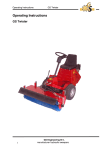
1
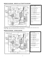
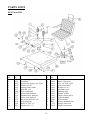
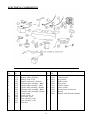
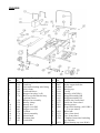
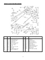
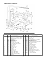
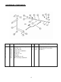
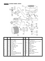
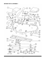
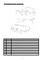
Deutscher Mowers Pty Ltd
OPERATORS MANUAL, PART 2
1400 ZTR ( Zero Turn Ride On Mower)
Table of Contents
Page No
1, 2
2
3
4
5
6
7
8
9
10 - 18
10
11
12
13
14
15
16
17
18
19
Topic
Table of Contents and Outline of Machine Functions.
Service Schedule
Adjustments, belt tensions, control levers.
Adjustments, handbrake.
Trouble Shooting Guide and Electrical System.
Removal, replacement of the mower deck.
Removal, replacement of the engine/ clutch assembly.
Removal, replacement of the hydrostatic transmission units.
Wiring diagram
Exploded view drawings and parts lists.
Seat and lid
Electrical components
Chassis
Height adjusting mechanism
Operators controls
Handbrake components
Engine and rear wheel drive
Deck assembly drawing
Deck assembly parts list
Rear discharge version – component parts.
Outline of Machine Functions
The Deutscher 1400ZTR ride on mower is fitted with a Briggs & Stratton engine or a Honda engine.
Both engines use a 12v starter system with its own charging system. A key switch is used to start the
engine on the control panel.
A single V belt is used to drive the transmissions from the engine. The hydrostatic transmission units
have an output shaft whose speed and direction of rotation can be varied independently of the input
shaft speed and rotation direction.
The output shaft of the left hand hydrostatic transmission is attached to the left rear wheel and the
output shaft of the right hand hydrostatic transmission is attached to the right rear wheel. A single “fixed
position” idler pulley adjacent to the engine is used to keep the drive belt tight.
The two hydrostatic transmission units are controlled by levers, as described in Part 1 of this manual,
and do not turn the wheels when the levers are in their neutral position.
The front wheels of the mower are “castors” and free to pivot in any direction.
An electric clutch on the engine is used to engage the cutters via a B section belt. The clutch is
switched on and off by a switch on the operators panel.
The fully floating side discharge “1400mm cut width” mower deck is suspended on four chains below
the frame of the mower, and is held forward by a V shaped frame which is adjustable in length.( To
tighten the deck drive belt). This ensures that the deck drive belt remains tight when the deck is raised
and lowered.
1
The mower deck is fitted with three disc blades, and the central blade is driven by the long belt from the
engine. The two outer blades are driven by separate belts from pulleys on the central blade shaft.
These outer belts can be separately tensioned.
The mower deck is braced sideways with a long steel rod which can move up and down as the deck
height is changed. The rod is spring loaded at the end to absorb minor collisions, by allowing the deck
to swivel slightly.
Raising the mower deck is accomplished by the operator pushing on a foot pedal which in turn moves a
mechanism to lift the deck. A large spring attached to the mechanism reduces the force required for
the lift. The deck will descend to its lowest height by gravity once the pedal is pushed slightly and a pin
is removed from the long height adjusting rod.
A lid under the operator’s seat allows easy access to the battery and the fuses.
The mower is fitted with a toolbox on the left mudguard, but this can be replaced with a fuel tank as an
optional extra.( This will double the fuel capacity.)
Lastly the mower has many safety features as mentioned in Part 1. These include an interlock which
prevents the mower being started when the handbrake is off, an interlock which stops blade rotation
when the handbrake is applied, a seat switch which turns off the engine if you dismount and a switch
under the battery lid which prevents the engine being started when the lid is raised. The handbrake is
incorporated in the right hand control lever, so when the lever is moved aside to exit the seat, the
handbrake is automatically applied.
Service Schedule
*
Frequency
100hrs
Component
Engine cooling air
screen.
Cooling Fins, engine
100hrs
Engine air cleaner
25 hrs
Spark plugs
Fuel filter
Battery
Hydrostatic units
Belts
Tyres
Handbrake
100hrs
100hrs
daily
10hrs or daily
50hrs
30hrs
As required
Hydro L shaped
control lever.
10 hrs
10hrs
Type of Maintenance
Brush clean.
Clean with air hose if available,(USE SAFETY GLASSES),
otherwise by hand.
Shake out dirt dry type. Wash sponge type pre-cleaner.
When not serviceable, replace.
Service or replace
Replace
Check water level, top up if necessary.
Externally clean. (assists cooling)
Check for wear and adjust.
Check for damage and air pressure.
Adjust linkage. (If the mower can be pushed with the
handbrake engaged.)
Lubricate mechanism pivot points with light oil.
Lubricate pivot bolt with light oil.
* More often under extreme conditions.
2
Adustments
1. Deck drive belt ( From engine to mower deck )
To check the belt tension, reach in to the centre of the belt, at the rear of the mowing deck, and grasp
the two sides of the belt in one hand. i.e. With your thumb around one side of the belt and your little
finger(s) around the other side, Squeeze your grip to test the belt tension. You should have about 15
mm movement inwards on each side. Do not over-tighten the belt. This may reduce bearing life etc.
To tighten the belt, loosen the front ¾” UNC nut on the large thread at the front of the mower deck by a
few turns. Turn the second nut on the same thread clockwise (facing forward) and with each half turn
recheck the belt tension as described above. Retighten the front nut.
2. Short blade belts (On mower deck)
It is easier to tension these belts if you have the deck removed, but it can be done with the deck on the
mower, and even with the belt guards in place. To tighten these belts, simply loose the 3/8” UNC nuts
on the belt idler pulleys, push the pulleys inwards by hand and retighten the nuts. It may be useful to
place a piece of wood behind the idler bracket when pushing it in.
Once tightened, the belt should deflect about 12-15 mm in the centre opposite the idler pulley when
forced inwards by hand.
Important! The idler pulley runs on the outside of the belt. Using incorrect belts can cause premature
belt failure, as not all belts are designed for this arrangement.
3. Hydrostatic transmission belt. (Under the engine)
Remove the left rear cover. (situated above the bumper bar)
To tension the belt, loosen the 8mm tensioner clamping bolt (on the left of the left engine mounting
plate) by one to two turns. Push the belt idler inwards with a force of approximately 5 – 8 kg, and while
holding this force, retighten the 8mm bolt.
OVERTIGHTENING THE BELT COULD CAUSE PREMATURE FAILURE OF THE HYDRO
BEARINGS. THE 5 – 8 kg FORCE IS ABOUT THE MAXIMUM MOST PEOPLE CAN ACHIEVE
WHEN PUSHING ON THE TENSIONER WITH THEIR THUMB. IF UNSURE OF THE FORCE
REQUIRED, USE A PIECE OF FLAT WOOD AND A SPRING BALANCE.
DO NOT USE A LEVER TO TIGHTEN THE BELT TENSIONER. YOU WILL VOID YOUR
WARRANTY.
You can check the belt tension by pushing the belt sideways at a point halfway between the right hydro
pulley and the engine pulley. The belt should deflect about 12mm when pushed sideways forcefully with
your thumb.
4. Hydrostatic Transmission control levers
If the two control levers are not opposite each other, or you wish their neutral position to be further
forward or backward, simply loosen the 8mm bolt (13mm spanner) at the base of each lever (facing
inwards), relocate the levers and retighten the bolts.
The length of the hydro control rods inside the mower are factory set and should not need adjusting.
3
5. Handbrake
To test the handbrake, park the mower on a smooth level surface and put the right hand control lever in
its “OUT” position. Try to push the mower with the freewheeling levers engaged. If the mower moves,
adjust the handbrake as follows.
With the right lever in the “IN” position, the free play on the handbrake lever where it joins the control
lever rod, should be approximately 1-2mm.( See diagram 1). If the free play is greater, tighten the nut
on the handbrake rod at the base of the machine under the front of the battery, until the required free
play is achieved. Recheck the handbrake operation by trying to push the mower with the brake
engaged.
If the method listed above fails to improve the handbrake function, the two castellated nuts on the sides
of the hydro units, at the rear, may need tightening. Please note there should still be a small amount of
free play in the levers under these nuts when the handbrake is off. Remove the split pins to turn the
castellated nuts, and replace the pins after winding in the nuts by hand.
6. Deck Tilt and Minimum Deck Height
If the deck is scraping on the ground at its lowest height, it can be raised at the front by relocating the
“pins holding the chains on the front of the deck” further rearward in the multi-holed brackets.( the multiholed brackets are welded to the top of the deck).
To raise the rear of the deck, remove the platform ( see para 2, page 6) and then tighten the nuts on
the long height adjusting rods. The nuts are on the left and right side of the mower, roughly near the
height adjusting pedal and the foot support. As you tighten, periodically measure the gap between the
top of the deck (at the front and the rear) and the side rails. The gap should be the same front to rear or
say 10mm narrower at the rear. A slight downward slope of the blades can produce a better cut.
Finally check that the four chains are tight. If one of the chains is loose, tighten the nut on the long rod
on the same side as the loose chain.
7. Removal of the Large Deck Spring
Remove the deck as described above, and the platform as described in para 2, page 6.
Slide the pedal well forward on the height adjusting rod (i.e. the rod with the multiple holes).
Grasp the height adjusting rod firmly and pull it towards the rear of the machine, at the same time
removing the pin you placed behind the bracket at the right front corner of the seat. Now allow the rod
to move forward slowly, until it stops.
Use a strong wire hook or sturdy rope, connected to the front of the spring, to pull the spring forward
and then down off the torsion bar bracket.
4
Trouble-shooting Chart
Problem
Mower will not start when the
key is turned.
Possible Cause
• Right hand lever in “IN” position.
• Blown fuse in starter solenoid circuit.
• Driver not sitting in the seat.
• Engine/ starter motor fault.
• Flat battery. (Especially if the starter solenoid clicks but the
engine does not turn over)
• Circuit fault. Follow circuit diagram, page 9.
Battery will not charge.
• Corroded or loose battery terminals.
• Defective battery.
• Inoperative diode or rectifier/regulator.
Battery discharges rapidly.
• Low water level.
• Defective battery.
Engine cranks slowly
• Weak or discharged battery.
• Corroded or loose electrical connections on the solenoid or
the battery.
Blades will not turn when
• Right hand control in the “OUT” position.
switched on at the panel.
• Clutch fault. Check power is getting to the clutch before
removing the clutch.
• Belt missing or slipping. See “adjustments”
• Circuit fault. Follow circuit diagram, page 9.
Engine will not turn off when
• Faulty ignition switch.
the key is turned off.
• Open circuit in engine earthing lead, either between the
engine and key switch, or between the key switch and earth.
Engine will not turn off when
• The switch under the seat is not operating when the seat lifts.
leaving the seat, without
• There is an open circuit in the earth wire from the engine to
turning off the ignition key.
the switch or from the switch to the chassis earth.
Poor grass discharge from
• Blades badly worn
chute.
• Belts slipping.
• Mower deck set too low for the conditions.
• Driving too fast for the conditions.
• Grass very wet.
Mower turning to the left or
• Control levers need adjusting. See “Adjustments”
right with the control levers
• Hydro belt slipping. To check, see “Adjustments”
held opposite each other.
• One or both hydro units faulty. See your mower dealer.
Mower not climbing up hills.
• Tyres slipping on grass.
• Hydro belt slipping.
• Faulty hydro units.
Electrical System Ref. Wiring Diagrams on Page 9.
1. The diode in the clutch circuit is installed to prolong switch life. FAILURE TO CONNECT THE
DIODE CORRECTLY WILL CAUSE A SHORT CIRCUIT.
2. The switch connected to the right hand control lever has a second function; it prevents the
mower being started unless the control lever is in the out position. This ensures the handbrake
is engaged when the mower is started.
3. See page 6, Part 1. The buzzer is installed to warn operators that the battery will go flat if they
leave the seat and do not turn off the ignition switch.
5
Deck Removal and Replacement
Removal
1. Position the mower on a level area where you wish to remove the deck, stop the engine, engage the
handbrake and lower the deck to its lowest height.
2. Loosen the large ¾” UNC nut at the front of the deck, in the centre under the front cross beam. Then
loosen a similar nut at the rear of the same bracket, so the blade drive belt from the engine becomes
slack. Removing the foot platform will make access to these nuts easier.
To remove the platform, pull the pin out of the height adjusting pedal and slide the pedal rearwards until
it touches the control panel. Remove the four screws retaining the platform. Remove the platform by
standing at the front, with your left hand in the slot through which the height adjusting mechanism
protrudes and your right hand under the right edge, then lift it aside.
3. Remove the long blade drive belt from the pulley on the deck.
4. Pull out the pin securing the deck sway brace to the mower. The pin is located at the base of the
chassis, just in front of the left hand wheel. Pull the sway brace bar off its support pin but leave it
connected to the deck.
5. If you removed the pin from the height adjusting pedal, slide the pedal forward so it is at least 300
mm away from the control panel.
Grasp the height adjusting rod (the long square tube with the pedal on it) firmly and pull it towards the
rear of the machine until the chains supporting the deck are loose. Place a bolt or the pedal pin in one
of the height adjusting holes, just behind the guide bracket at the front right hand side of the seat, then
slowly release your grip on the rod. The four deck chains should remain loose.
6. Pull out one of the R clips on the main deck pin at the front of the deck, and remove the pin. Lift the V
frame off the deck and place a short piece of pipe or plastic tube over the front height adjusting system
torsion bar and onto the belt tensioning bolt. This will hold the V frame off the deck.
7. Remove the four pins at the bottom of the chains which support the deck.
8. Release the handbrake on the mower and the 2 freewheeling levers at the rear of the mower. Grasp
the front cross beam of the mower, lift the beam and walk the mower backwards over the deck.
Replacement
Replacing the deck is the reverse of the above sequence.
6
Engine/Clutch Removal
Removal
1. The clutch cannot be removed from the engine when it is in the in the mower, so to service the clutch
or the engine, remove the engine and clutch as an assembly. The engine mounts have been cut away
so this can be accomplished relatively easily.
2. Use only an approved crane or engine lifting device to lift the engine form the mower.
3. Turn off the ignition key or disconnect the battery. Release the power lead to the clutch by
unplugging it on the inside of the firewall, then loosening the cable clamp. Remove all other wires
leading to the engine, being careful to tag them (for ease of replacement) before they are removed.
4. Remove the covers on either side of the engine.
5. Remove the blade drive belt as described in “Deck removal and Replacement”.
6. Release the tensioner for the hydro drive belt and pull the tensioner fully backward in its slot. If this
does not enable you to remove the hydro drive belt easily, remove the tensioner completely. Remove
the hydro drive belt.
7. Drain the engine oil. See engine booklet.
8. Disconnect the fuel line from the engine, being careful not to spill fuel. DO NOT SMOKE OR
PERFORM THIS TASK ANYWHERE NEAR A NAKED FLAME. TURN OFF MOBILE PHONES.
9. Remove the four engine bolts and the spacer above the strap to the clutch. Note carefully the
position of the clutch strap. i.e. on the right side, with the spacer ABOVE the strap. The strap must be in
tension with the engine running and blades driving.
10. Loosen the other end of the clutch strap and turn it in towards the crankshaft.
11. Place strong straps around the engine and, using a winch rated for the purpose, carefully raise the
engine and clutch assembly. Never position yourself under the assembly once it is raised, and keep
bystanders away. Lift the engine just above the rear of the mower and lock the lifting device.
12. Release the freewheeling levers on the back of the mower, and slowly draw the mower away from
the engine.
13. Lower the engine carefully to the ground or bench and sit it on blocks.
Replacement
Replacement of the engine clutch assembly is the reverse of the installation. Great care must be taken
to avoid damaging the clutch pulley during this operation.
Don’t forget to reconnect the clutch strap, and to tension the belts as described in the “Adjustments”
section. Ensure no contamination gets into the fuel line, as this will end up in the carburettor.
7
Hydrostatic Transmission Removal/ Replacement
Removal
1. This task is a lot easier with the engine/ clutch assembly removed, the seat removed and the battery
box removed. IT IS IMPERATIVE THAT THE MOWER IS ON A LEVEL SURFACE.
2. To remove the seat, disconnect the wiring under the seat, but carefully tag the wiring first. Then
remove the bolt/ hinge pin on the left front corner of the seat. Slide the seat panel to the left and it will
come off the right hand hinge pin.
3. To remove the battery box, first take off the battery strap, then remove the battery. Next undo the
bolts on either side of the battery box, and remove the box.
4. Using a jack, mount the rear of the machine on 2 car stands positioned near the two rear corners and
under the side plates.
5. Remove the two rear wheels.
6. Disconnect the pin across the rear of the machine, underneath the clutch pulley, which is connected
to the handbrake levers on the rear of the hydro units. Remove the spring which is connected to the
handbrake rod, on top of the chassis. Slide the handbrake rod forward.
7. Remove the springs from the ends of the freewheeling levers, then remove the levers from the hydro
units. Withdraw the levers from their guides and place them aside.
8. Remove the frame (chassis) from underneath the hydro units. IF YOU PUT YOUR ARM UNDER
THE MACHINE, ENSURE THE MOWER IS VERY SECURE ON THE CAR STANDS. A security block
or drum under the centre of the machine is recommended.
9. The hydro units can now be removed by disconnecting and removing the bolts which hold them to
the chassis side plates. If you do not have sealing plugs for the hydro units, keep the plastic tubular
vent facing upwards at all times, even during removal.
Replacement
Replacement of the hydro units is the reverse of the installation. Ensure the wheel bolts are tensioned
to 40ft lb, 54 Nm, and the engine bolt through the clutch is tightened to 50ft lbs, 68 Nm. Use new nyloc
nuts on the hydro bolts if they have been removed more than once before. DO NOT FORGET TO REINSTATE THE VENT PIPES IN THE HYDRO UNITS.
Tension the blade belt and the hydro belt as specified in the “Adjustments” section.
8
WIRING DIAGRAM – BRIGGS and STRATTON ENGINE
Wire No. / end fitting/ length mms,
colour / end fitting
1 FS (870,yellow)MS (50 , yel) B –
diode - B (100, yellow) O
2 FS (510, yellow) FS
3 FS (300, blue) FS
4 FS (770 , blue) FS
5 FS (630,red) FS
6 FS (820,red) FS
7 FS (280,green) O
8 O (500,green) FS (80,green) FS
9 O (110,green) MS
10 FS (600,grey) FS (160, yellow) FS (430,yellow) FS (540,red) B
11
12
13
14
15
16
17
FS (300,black) B
FS (490, green) O
FS (650,black) FS (760, black) MP
FS (120, grey) FR
FS (50,red) FS (300,red) O
FS (110,blue) FS
FS (110, red) FR
Wires 1 – 17 are pvc coated, 2.2mm
diameter.
End fittings = FS (1/4” female spade), MS (1/4” male spade), O ( ¼” round hole), FR (4mm female round
socket), MP ( 4mm male round pin), B ( bare end, 15mm wire)
WIRING DIAGRAM – HONDA ENGINE
Wire No. / end fitting/ length mms,
colour / end fitting
1 FS (870,yellow)MS (50 , yel) B –
diode- B (100, yellow) O
2 FS (510, yellow) FS
3 FS (300, blue) FS
4 FS (770 , blue) FS
5 FS (630,red) FS
6 FS (820,red) FS
7 FS (280,green) O
8 O (500,green) FS (80,green) FS
9 O (110,green) MS
10 FS (600,grey) FS (160, yellow) FS (430,yellow) FS (540,red) B
11
12
13
14
15
16
17
FS (300,black) B
FS (490, green) O
FS (650,black) FS (760, black) MP
FS (120, grey) FR
FS (50,red) FS (300,red) O
FS (300, blue) FS
FS (110,red) FR
Wires 1 – 17 are pvc coated, 2.2mm
diameter.
9
PARTS LISTS
SEAT and LID
Item
No
1
2
3
4
5
6
7
8
9
10
11
12
13
14
Part
No
1394
1072
1407
1019
1018
1017
1040
1817
1330
1371
1372
1819
1058
1059
Part Description
Seat spring (was T535)
Nut 8mm
Plastic cap, spring (was T536)
Washer 8 x 20
Spring washer 8mm
Bolt M8 x 20
Seat switch stud
Microswitch bracket
Standard seat, KAB P2
Delux seat, KAB U2
Back rest, KAB P2 seat
Seat base plate
Bolt3/8” UNC x 1”
Washer 3/8” x 1”
Item
No
15
16
17
18
19
20
21
22
23
24
25
26
27
10
Part
No
1818
1063
1062
1054
1019
1099
1816
1821
1815
1945
1946
R87
1132
1814
Part Description
Seat hinge bracket
Bush – seat pivot
Nut, 3/8’ UNC nyloc
Seat lid assembly
Washer 8 x 20
Nut 8mm nyloc
Earthing strap
Washer 50 Dia
Engine cutout spacer
Nylon insulator
Nylon washer
Spring, Standard seat
Spring, delux seat
Engine cutout plate
ELECTRICAL COMPONENTS
Item
No
1
2
3
4
5
6
7
8
9
10
11
12
13
Part
No
1263
1373
1374
1395
1396
1397
1810
1398
1811
1154
1259
1260
1254
1253
1252
Part Description
Lid & handbrake switch
Battery cable (245mm)
Battery (was T315)
Engine earth lead. (180mm)
Throttle plate assembly - B&S
Choke cable assembly – B&S
Choke cable assembly - Honda
Throttle cable assembly - B&S
Throttle cable assembly- Honda
Cable clamp
Screw 5mm x 15
Nut 5mm, nyloc
Fuse 10 amp (2 off)
Fuse 20 amp (2 off)
Fuse box
Item
No
14
15
16
17
18
19
20
21
22
23
11
Part
No
1255
1135
1261
1262
1256
1333
1947
1250
1712
3063
Part Description
Starter solenoid (B&S only)
Control panel
Key switch
Blade switch
Hour meter
Electric clutch
Micro switch
Wiring loom, incl buzzer
Buzzer
Battery cable (Honda 560mm)
CHASSIS
Item
No
1
2
3
4
5
6
7
Part
No
1187
1329
1393
1399
1364
1311
1370
8
9
10
11
12
13
14
15
16
17
1129
1120
1119
1004
1003
1308
1376
1145
1140
1143
Part Description
Tank strap (2 off)
Tank cap
Fuel tank including inlet fitting
Hose clamp
Tank outlet hose
Bumper bar plug (2 off)
Roll over protection bar assy
(optional extra)
Bumper bar assembly
Battery clamp
Battery box
Engine cover RH
Engine cover LH
Toolbox
Chassis assembly
Plastic knob
Footrest plate
Coach bolt
Item
No
18
19
20
21
22
23
24
25
26
27
28
29
Part
No
1136
2087
1064
1191
1198
1199
1192
1193
1356
1357
1201
1200
30
31
32
-
1202
1353
1354
1760
33
1231
12
Part Description
Platform assembly
Hydro support bracket
Subframe
Bearing cap
Circlip
Bearing ( 6205-2RS )
Kingpin assembly RH
Kingpin assembly LH
Outside rim, front wheel
Inside rim, front wheel
Bearing spacer
Front wheel bearing ( 6203-2RS )
(Two per wheel.)
Wheel nut
Tube, front wheel
Tyre, front wheel
Complete front wheel including
tyre and tube.
Wheel bearing cap (was R100)
HEIGHT ADJUSTING MECHANISM
Item
No
1
2
3
4
5
6
7
8
9
10
11
12
Part
No
1358
1276
1153
1378
1059
1436
1167
1171
1062
1172
1173
1437
Part Description
Cable, height adjusting pin
Height adjusting pin
Self tapping screw
Washer 3/16”
Plain washer 3/8” ID
Bolt, 3/8” Whit x 1”
Chain, 5 links
R clip
Nyloc nut 3/8” UNC
Deck pin
Height adjusting tube
Bolt, 3/8” Whit x 2”
Item
No
13
14
15
16
17
18
19
20
21
22
23
13
Part
No
1159
1183
1178
1379
1174
1359
1166
1175
1062
1053
1160
Part Description
Lift lever, rear deck
Pedal pin
Pedal assembly
Bolt 3/8” Whit x 3”
Height adjusting rod
Plastic plug
Spring, deck lift
Height adjusting swivel
Nyloc nut 3/8” UNC
Stepped bolt
Torsion tube assembly
OPERATOR’S CONTROLS
Item
No
1
Part
No
1106
2
3
4
5
6
7
8
9
10
11
12
13
14
15
16
17
18
1114
1109
1112
1098
1103
1091
1099
1417
1059
1416
1072
1019
1328
1097
1081
1113
1116
Part Description
Control lever assembly, L&RH
(Includes items 2,3,4, 17 & 18.)
Handgrip set
Release assembly
Plastic knob
Bolt M8 x 30
Rose joint , 5/16” UNF
Vertical rod, hydro control
Nyloc nut M8
Nut 10 mm
Washer 3/8” x 1”
Bolt M10 x 40
Nut M8
Washer 8 x 20
Bolt M8 x 50
Support, RH control
Support, LH control
Spring, release assembly
Pop rivet
Item
No
19
20
21
22
23
24
25
26
27
28
29
30
31
32
33
14
Part
No
1118
1117
1404
1428
1073
1085
1076
1314
1132
1344
1133
1096
1342
1088
5002
1093
Part Description
Bolt M8 x 40
Nylon roller
Over-travel device - assembly
Nut 5/16” UNF
Pivot block assembly
Nylon bearing half (2 each side)
RH control assembly
Split pin
Spring RH control
5/8” x 1” washer
Spring, LH control
LH control assembly
Bolt M8 x 25
Right angled lever ( 2 off)
Bronze bush ( not shown, fits
in lever No 32.)
¼” W threaded rod
HANDBRAKE COMPONENTS
Item
No
1
2
3
4
5
6
7
8
9
Part
No
1082
1017
1099
1029
1030
1019
1350
1031
1028
Part Description
Top plate, handbrake pivot
Bolt M8 x 20
Nyloc nut M8
Hydro lever, handbrake
Roller tube
Washer 8 x 20
Split pin
Handbrake tie rod
Rod assembly, handbrake
Item
No
10
11
12
15
Part
No
1352
1345
1015
Part Description
Tension spring
Handbrake lever assembly
Washer ½”
ENGINE and REAR WHEEL DRIVE
Item
No
1
1A
2
3
4
5
6
7
8
9
10
11
12
13
14
15
Part
No
1331
1386
1016
1015
1014
1017
1018
1019
1013
1011
1272
1024
1020
1267
1268
1340
Part Description
Engine, B&S
Engine, Honda
Nyloc nut M12
Washer ½” x 1”
Idler pulley ½” x 3” (was T618)
Bolt M8 x 20
Spring washer 8mm
Plain washer 8 x 20
Bolt M12 x 45
Idler arm
Drive belt
Spring
Latch assembly
Hydrogear transmission, LH
Hydrogear transmission, RH
Rear tyre 20”
Item
No
Part
No
16
1341
17
1383
18
1339
19
2064
20
1338
21
1333
22
1270
23
1271
24
1335
25
1336
26
1337
27
1400
27A 1380
28
1384
29
1381
16
Part Description
Wheel nuts
Rear wheel rim
Crankshaft bolt 7/16” x 3” UNF
Spring washer 7/16”
Stepped collar
Clutch
Clutch strap
Clutch strap spacer
¼” key x 29
Pulley 4”
Collar, crankshaft top
Muffler B&S
Muffler Honda
Cap screw 5/16”x20 UNC
Muffler gasket
MOWING DECK ASSEMBLY
17
Mowing Deck Parts List
Item
No
1
2
3
4
5
6
7
8
9
10
11
12
13
14
15
16
17
18
19
20
21
22
23
24
25
26
27
28
29
Part
No
1228
1274
1227
1316
1046
1049
1015
1245
1203
1210
1247
1275
1014
1428
1018
1019
1241
1243
1233
1237
1171
1239
1094
1238
1000
1286
1292
1291
1273
Part Description
Belt cover RH
V belt, deck drive
Belt cover LH
Bolt ½” x 3” HT UNF
V frame pivot bush
Nut, ½” UNF
Plain washer ½”
Spring washer ½”
V frame assembly
Nut 3/4” UNC
Spring washer 3/4”
V belt, deck outer
Idler pulley 3”
Nut 5/16”UNF
Spring washer 8mm
Plain washer 8mm
Blade belt tensioner (Left hand)
Blade belt tensioner (Right)
Sway brace
Washer ½” x 7/8”
R clip
Split pin ( 3/16” x 1”)
Spring, sway brace
Washer ½” x 1” x 1/8”
Plastic discharge chute
Hinge plate assembly
Hinge pin – flap
Starlock clip, 8mm
Flap spring
Item
No
30
31
32
33
34
35
36
37
38
39
40
41
42
43
44
45
46
4750
51
52
53
54
18
Part
No
1105
1314
1282
1279
1211
1248
1171
1207
1319
1325
1296
1323
1320
1385
1388
1294
1406
H651
H650
H652
G36
1060
R32
1382
Part Description
Roll pin 3mm x 20
Split pin 3mm x 25
Axle, deck roller
Deck roller
Deck frame – Welded to item 55
on later models.
Deck retaining pin
R clip
V frame coupling
Nut 1” UNF
Centre pulley assembly
Key ¼” x 80
Double pulley (1 off)
Outer pulley,deck (2 off)
Spindle assembly, outer
Spindle assembly. Centre
Spindle housing
Spindle bearing (6206. 2NSE)
Blades only x 2
Blade, bolt, nut,washer x 2
Bolt, nut, washer set x 2
Disc retaining bolt
Spring washer 3/8”
Blade plate assembly
Deck welded assembly
Rear Discharge Version - Components
Item
1
2
3
4
5
6
7
8
9
10
11
12
Part No
1769
1957
1762
1775
1062
1058
1776
1799
1804
1785
1791
1792
Part Description
Rear discharge deck assembly.
Honda muffler VSM3
Self threading screw
Chassis plate
Nut, nyloc, 3/8”
Bolt, 3/8” x 1”
Bumper bar assembly, rear discharge.
Air cleaner, Honda No.
Air cleaner hose.
Air intake extension - adaptor
Hose Clamp 25 - 40 mm (2off)
Hose clamp 40-60 mm (1 off)
19