1
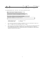
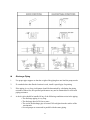
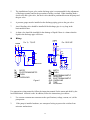
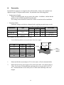
5. The installation of a gate valve on the discharge pipe is recommended for the adjustment of discharge quantity and for the prevention of motor overload. When installing both a check valve and a gate valve, the check valve should be positioned between the pump and the gate valve. 6. A pressure gauge must be installed on the discharge piping, prior to the gate valve. 7. An air bleeding valve should be installed if the discharge pipe is very long in the horizontal direction. 8. A drain valve should be installed for the drainage of liquid if there is a chance that the liquid in the discharge pipe will freeze. Wiring POWER S T R POWER R S T For ½ - 7½ HP For 10-25 HP MCB OLR OLR OLR OFF PBS PUSH BUTTON MC MC MC ON U VW M XYZ OFF ON AR TR AR M TR PUSHBUTTON MCY MCY MC AR MC TR AR MC Y M MC ON OFF OLR M ON OFF MC MC MC OLR TR AR MOTO ELECTROMAGNETIC PUSH OVERLOAD Figure 6 MOTO PUSH ELECTROMAGNETIC NONFUSE ELECTROMAGNETIC OVERLOAD TIME AUXILIARY Use appropriate wiring materials, follow the instruction manual for the motor and abide by the local and national electrical codes. In addition, follow the instructions given below: 1. Use a motor contactor that conforms to the specifications (voltage, current, etc.) of the pump motor. 2. If the pump is installed outdoors, use waterproof wiring to protect the switches from rainwater and moisture. 13