1
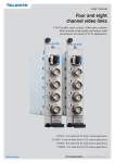
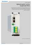
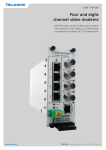
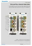
User manual
Four and eight
channel video links
CFO First Mile series consist of fibre optic modems
which provide a high quality and losless video
transmission for variety of CCTV applications.
CFO410 - 4 ch video link for fixed camera applications
CFO420 - 4 channel video link for PTZ camera applications
CFO810 - 8 ch video link for fixed camera applications
CFO820 - 8 ch video link for PTZ camera applications
CFO410/420/810/820 user manual, 59300426, rev001
Contents
Optical Transmitter & Receiver................................................................................................................................ 3
Introduction......................................................................................................................................................... 3
Features.............................................................................................................................................................. 3
Frame installation................................................................................................................................................ 4
Stand-alone installation....................................................................................................................................... 4
Video connections and indicator leds................................................................................................................. 4
S-video operation................................................................................................................................................ 4
Receiver alarm connection (all models).............................................................................................................. 4
Transmitter (CRT420/820) data wiring settings................................................................................................... 5
Receiver (CRR420/820) data mode and wiring settings..................................................................................... 6
Data termination and biasing.............................................................................................................................. 8
Link indicator led................................................................................................................................................. 9
Fibre connection................................................................................................................................................. 9
SFP transceiver module.................................................................................................................................... 10
To plug-in and unplug the SFP module, follow these steps.............................................................................. 10
Technical Specifications......................................................................................................................................... 11
CFO410/420/810/820 user manual rev001
Optical Transmitter & Receiver
Single/multimode 4 and 8 channel video links for video
only or video & bi-directional data operation
CFO410 video link
Welcome, and thank you for purchasing Teleste’s CFO Products.
Vx4
Introduction
CFO420 video link
Vx4 Dx1
CFO810 video link
Vx8
CFO820 video link
Vx8 Dx1
The CFO410/810 series is a basic building block for multi-channel video
transmission system providing uni-directional transmission of 4 / 8 uncompressed video channels over optical fibre.
The CFO420/820 series is a basic building block for multi-channel video
transmission system providing uni-directional transmission of 4 / 8 uncompressed video channels with one bi-directional data over optical fibre.
PAL and NTSC video formats are supported to provide a transparent video transmission. With CFO420/820 models it is also possible to transmit
one bi-directional RS data channel e.g. for PTZ control. All common data
protocols are supported and are easily configurable by DIP switches.
Optical transmission is based on hot-swappable SFP optics (class 1M).
The high speed optics enable a full quality and a zero-delay (latency free)
video transmission. Available SFP options are supporting 2 km transmission over multimode fibre or 20/40 km operation over single-mode fibre.
As with all CFO Platform products the units meet all standard EMC and
environmental requirements.
All units are fully compatible with all CFO rack systems. Stand-alone
options are available with the CMA module adapter and a separate
mains adapter.
Features
•
•
•
•
•
•
•
•
•
•
•
•
CFO410/420/810/820 user manual rev001
Four and eight channel video multiplexer
Alternative SFP optics for various optical needs
Standard alternatives 2 km MMF, 20km SMF and 40 km SMF
Four / eight CVBS (PAL/NTSC) video channels
Video SNR 60 dB typical, 8 bit video sampling
Data model supports RS-232, RS-422 or RS-485
Data rate up to 230 kbps
Uncompressed zero delay digital transmission
Common card units for rackmount or stand-alone installations
Compatible with all CFO installation systems
EMC and environmental conformance
Feasible for temperature hardened operation (-34…+74 °C)
3
Frame installation
1
OPTICAL TRANSMITTER
2
IN-
3
LINK
DATA
IN+
OUTOUT+
GND
4
VIDEO 1
VIDEO 2
VIDEO 3
The CFO unit is to be pushed along the guide rails into the installation
frame (e.g. CSR216 or 316 series) and secured with the four locking
screws. The unit can be freely positioned in any slot in the frame.
(Alarm card slot excluded). The empty positions in the frame should be
blanked off with cover plates. The supply voltage is to be provided by
a CPS384 or CPS390 power supply unit.
Stand-alone installation
The unit can be installed for stand-alone use by using a CMA series
module adapter. The unit is to be pushed along the guide rails into the
CMA module adapter and secured with locking screws. The stand-alone
unit should be mounted to a vertical surface. The +12 VDC supply
voltage is supplied by the means of a separate mains adapter with a
regulated output, (e.g. CPS221 for CMA011 or CPS231 for CMA025).
Video connections and indicator leds
VIDEO 4
5
An example view for CRT420 optical
transmitter (same information applies
respectively to receiver unit CRR420).
1) Locking screw (4 pcs)
2) DATA connector (5-pin screw terminal)
Note! Video only models do not contain a
data connector (CFO410 & 810 series).
3) Slot for SFP optical tranceiver and link
status led
4) Video input (BNC female) and video indicator led
5) Handle (with unit information)
The impedance of the video connection (BNC female) is 75 Ω.
The nominal input/output level is 1 Vpp. Video connection is equipped
with the dual colour VIDEO led on the front panel. See table below for
explanation of VIDEO indicator led’s lights.
Colour
Status
Green
A signal is present and in nominal level
Yellow
No video signal, or the video level is too low
VIDEO indicator operation.
S-video operation
It is also possible to transmit two (CFO410/420) or four (CFO810/820)
S-video signals that comprises separate luminance (Y) and chrominance
(C) signals. This, however, uses two channels per one transmission
channel. Connect Y and C signals to any of video inputs. Make sure that
the Y and C connections are corresponding both at transmitter and
receiver. No extra adjustments are needed.
Receiver alarm connection (all models)
Alarm at the rear connector of the unit is an open collector output, with
the capability of 30 V/10 mA switching (alarm status = low imp.).
Alarm
Description
Reason
B
Link status alarm
No synchronisation achieved at
optical input.
Refer to documentation of CCU001/002 rack alarm cards.
4
CFO410/420/810/820 user manual rev001
IN-
1
IN+
2
OUT-
3
OUT+
4
GND
5
Transmitter (CRT420/820) data wiring settings
The CFO420/820 link provides one bi-directional data channel
(CRT <--> CRR). The connector in use is a screw terminal connector.
Available data modes for data channel are RS232, RS422, RS485-2w
and RS485-4w. See table below how to connect the desired data
mode. The desired data connection must be confirm by the means of
DIP switces. The desired data mode settings for data channel can be
set by the means of receiver’s DIP switces (see page 7 for detailed
description). The default factory setting is RS485-2w + dwelltime 75
µs, no line bias and no term.
DATA connector (5-pin screw terminal).
Pin
RS232
RS422
RS485-2w
RS485-4w
in -
in / out -
in -
in / out +
Data inON
1 2 3 4 5 6
CRT420/820 DIP switches (SW1) for
setting of pinout wiring.
Data in+
in
in +
Data out-
out
out -
out -
out +
out +
Data out+
in +
Screw terminal connector’s data pinout.
Data type
RS232
DIP switch position
1
2
3
4
off
off
off
5
off
off
RS422
off
off
RS485-2w
on
on
RS485-4w
off
off
- line bias
on
on
- no line bias
off
off
- termination
on
- no term.
off
Data connection settings for SW1 (DIP switch no 6 is not in use).
CRT420/820 top view
DIP swithes are located on the top of device.
CFO410/420/810/820 user manual rev001
5
Receiver (CRR420/820) data mode and wiring settings
CRR420/820 DIP switches (SW2) for data
mode selection.
The desired data mode settings including dwelltime settings for RS4852w can be set by the means of DIP switces. The default factory
setting is RS485-2w + dwelltime 75 µs, no line bias and no term.
RS485-2w Dwelltime settings
Tx data
Rx data
Data mode
Dwelltime ms
Dip 1
Dip 2
Dip 3
Dip 4
Dip 5
Dip 6
Dip 7
Dip 8
0,01
on
on
on
on
on
on
on
on
RS232
0,02
off
on
on
on
off
on
off
on
RS422
0,04
on
off
on
on
on
off
on
off
RS485-2w
0,075
off
off
on
on
off
off
off
off
RS485-4w
0,1
on
on
off
on
0,2
off
on
off
on
0,4
on
off
off
on
0,6
off
off
off
on
1
on
on
on
off
1,2
off
on
on
off
2
on
off
on
off
3
off
off
on
off
4
on
on
off
off
6
off
on
off
off
8
on
off
off
off
10
off
off
off
off
Data mode selection and RS485-2w dwelltime settings (SW2).
Left side view
CRR420/820 top view
CRR420/820 DIP switches. Note! The data mode is only selected in the receiver.
For SW1 please refer to page 5 for settings.
6
CFO410/420/810/820 user manual rev001
Data formats
RS232 is an unbalanced data format (i.e. the signal wire working against a
reference – ground). Simplex RS232 requires two connections (signal and
ground). Full-duplex RS232 requires three connections (signal TX, signal RX
and ground).
RS422 is a balanced data format. Simplex RS422 requires three data connections (+/- and ground). Full-duplex RS422 requires five data connections (in+/
in-, out+/out- and ground).
RS485 is used for full-multipoint communications where multiple transceiver
devices may be connected to a single twisted-pair signal cable. Most RS485
systems use a Master/Slave architecture, where each Slave unit has a unique
address and responds only to packets addressed to that unit. Packets are
generated by the Master (e.g. CCTV controller keyboard), which periodically
‘polls’ all connected Slave units (e.g. CCTV camera receiver units). The Slave
unit that has been addressed then sends the appropriate reply packet back to
the Master. Slave units have no means of initiating communication without the
risk of a collision so they need to be assigned the ‘right to transmit’ by the
Master (by polling). RS485 exists in two versions, 2-wire and 4-wire.
CRR420/820
Master
4
+
CRT420/820
+
Tx
Tx / Rx
-
3
Slave
+
4
+
-
3
-
-
1
+
2
Tx
-
Tx / Rx
Fibre
1
-
2
+
Rx
Rx
5
5
GND
GND
RS485-2w data connection diagram.
A 2-wire RS485 network is implemented as a half-duplex system using single
twisted-pair cabling. This means that data can flow in both directions but only
in one direction at a time. As the fibre links not synchronised with master/
slave devices trasmit - receive turn-time (aka dwelltime) needs to be manually
selected. See the table on left for selectable predefined turn-time values.
CRR420/820
Master
4
+
Tx
CRT420/820
+
-
3
4
+
-
3
-
-
1
-
2
+
+
Tx
Slave
Tx
Tx
-
Fibre
1
-
Rx
Rx
+
2
5
GND
+
Rx
Rx
+
5
GND
RS422 / RS485-4w data connection diagram.
A 4-wire RS485 network can be implemented as a full-duplex system
using two twisted-pair buses where each bus is used for each direction of
transmission. In full-duplex mode the turn-time value is ignored.
CFO410/420/810/820 user manual rev001
7
Data termination and biasing
Termination is used to match impedance of a node to the impedance
of the transmission line being used. When impedance are mismatched,
the transmitted signal is not completely absorbed by the load and a
portion is reflected back into the transmission line. If the source, transmission line and load impedance are equal these reflections are eliminated.
Biasing -> the lines will be biased to known voltages and nodes will not
interpret the noise from undriven lines as actual data; without biasing
resistors, the data lines float in such a way that electrical noise sensitivity is greatest when all device stations are silent or unpowered.
RS485
2-wire
Line
Termination
Line
Biasing
+5V
680Ω
+
Rx
2
120Ω
1
-
680Ω
-
3
Tx
4
+
Data mode
Input termination options
RS232
None
RS422
No term (with failsafe)
Line termination (120 Ω)
RS485 - 2w
No term (with failsafe)
Line bias (forced 680 Ω line biasing)
Line termination (120 Ω)
RS485 - 4w
No term (with failsafe)
Line bias (forced 680 Ω line biasing)
Line termination (120 Ω)
Data input termination options for data channels. Data termination connects 120 Ω
between pins. Hard line bias connects 680 Ω (+input) to +5V and GND (- input).
8
CFO410/420/810/820 user manual rev001
Link indicator led
The status of optical link is indicated by a led next to the SFP slot.
2 fibre version
Tx
1 fibre version
Rx
Tx/Rx
SFP optical transceiver module.
Colour
Status
Green
Optical signal level is adequate and syncronization on link
level is achieved
Yellow
Optical signal is missing or input level is too low
LINK indicator operation. Note! On unidirectional links (CFO410/810) the led at
the transmitter module is always green.
Fibre connection
The optical interface is a small form-factor pluggable (SFP), see picture
beside. The optics is hot-swappable. Optical cable connector in use is
type LC. The optical operation depends on the type of selected SFP
transceiver module. This information is marked to the model’s type
sticker which is located on the side of the unit.
Note! CFO410S multimode model requires only one fibre for the
video transmission although the SFP in use is bi-directional.
Optical connector is type LC.
INVISIBLE LASER
RADIATION
CLASS 1
Optical connection meets class 1M
laser safety requirements of IEC
60825-1: 2001 and US department of
health services 21 CFR 1040.10 and
1040.11 (1990) when operated within
the specified temperature, power
supply and duty cycle ranges.
CFO410/420/810/820 user manual rev001
When installing the fibre optic cable, do not exceed the minimum
bending radius when connecting cable to the system.
Note! For correct optical operation and to ensure quality connections between fiber optic devices it is important that every fiber
connector be inspected and cleaned prior to mating. Connectors
should always be cleaned with professional cleaning equipment
and accessories for fibre optics. The optical connectors on the
equipment should always be protected with dustcaps when there
is no fibre inserted.
Any contamination in the fibre connection can cause failure of the
component or failure of the whole system. Even microscopic dust
particles can cause a variety of problems for optical connections.
A particle that partially or completely blocks the core generates
strong back reflections, which can cause instability in the laser
system. Dust particles trapped between two fibre faces can
scratch the glass surfaces. Even if a particle is only situated on
the cladding or the edge of the endface, it can cause an air gap
or misalignment between the fibre cores which significantly
degrades the optical signal.
9
SFP transceiver module
If your transmission requirements change, simply unplug the existing SFP
module, and plug-in the new module. Keep the protective dust plugs on the
unplugged fibre-optic cable connectors and the transceiver optical bores
until you are ready to make a connection. Save the dust plugs for future
use. Be sure to clean the optic surfaces of the fiber cable before you plug
the cable into another module. When using 2 fibre version SFP, check the
order of the Tx/Rx ports.
Bale clasp
latch
SFP module’s locking release points.
To plug-in and unplug the SFP module, follow these steps
Remember to use personal grounding device to prevent ESD occurrences
when installing SFP module.
To plug-in the module:
1.Do not remove the optical bore dust plugs. Open the bale clasp on the
SFP module by pressing the clasp downward until it is in a horizontal
position. Then insert the SFP into the socket by pressing the SFP into the
slot firmly with your thumb until you feel the connector latch into place.
4.Verify that the SFP is seated and latched properly by trying to remove it
without releasing the latch. If the SFP can not be removed, it is installed
and seated properly. If the SFP can be removed, reinsert it and press
harder with your thumb, repeating if necessary until it is latched securely
into the socket.
To unplug the module:
1.Disconnect the network fibre optic cable from the SFP transceiver module
connector (immediately reinstall the dust plugs in the SFP transceiver
module’s optical bores and the fiber-optic cable LC connectors).
2.Pull the out and down to eject the SFP transceiver module from the
socket connector. If the bail clasp latch is obstructed and you cannot use
your index finger to open it, use a small, flat-blade screwdriver or other
long, narrow instrument to open the bail clasp latch. Grasp the SFP
transceiver module between your thumb and index finger, and carefully
remove it from the socket. Place the removed SFP transceiver module in
an antistatic bag or other protective environment.
10
CFO410/420/810/820 user manual rev001
Technical Specifications
Optical
General
SFP plug-in optics
see block diagram examples
Supply voltage
2 km multimode
1310 & 1310 nm
bidi 2-fibre
20 km singlemode
1310/1550 nm
bidi 1-fibre
Current consumption2) 360 mA
550 mA
CRT/CRR410&420
CRT/CRR810&820
40 km singlemode
1310/1550 nm
bidi 1-fibre
Connector
Single or duplex-LC
Dimensions
3U x 5HP x 190 mm
3U x 10HP x 190 mm
CFO410
CFO420/810/820
Weight
0.45 kg
0,5 kg
0,65 kg
CRT/CRR410
CRT/CRR420
CRT/CRR810&820
IP Housing
00
Video
Number of channels
4 composite video
8 composite video
Sampling frequency
13.88 MHz
Sampling resolution 8 bits
Source and load impedance 75 ohm
Input and output signal levels
1 Vp-p
Input overload level
1.5 Vp-p
Insertion gain
+/- 5%
Bandwidth
5.5 MHz
C/L gain inequality
+/-5%
C/L delay inequality
40 ns
Differential gain
2%
Differential phase
1º
S/N ratio
better than 60 dB
Connector
BNC female
CFO410/420
CFO810/820
DC component
-3 dB
10.5...14 VDC
regulated
dry indoor required
Operating temperature -34...+74 ºC
Storage temperature -40...+80 ºC
Humidity
0...90%non-condensing
Indicators LEDs
Video presence, link status
Alarm
Link status EMC conformance
EN61000-6-3, EN50130-4
B-alarm (open collector)
Optical conformance
EN 60825-1, FDA 21 CFR 1040.21 and 1040.11
Safety
EN 60951-1
OtherRoHS
Notes
unified weighted ITU-T J.61
1)
Class 1M Laser product
2)
Max, operational with SFP
Data
Number of channels
1
CFO420/820
Data format
RS232 bi-state, 3-wire, EIA RS232C
RS422 bi-state, 4-wire, EIA RS422
RS485-2W tri-state, 2-wire half-duplex, EIA RS485
RS485-4W tri-state, 4-wire, EIA RS485
485/422 specific
Line termination
selectable
Line bias
selectable
Half-duplex dwell-time selectable values
Data rate
0...230 kbps
Sampling rate
16 MHz
Connector
5-pin screw terminal
CFO410/420/810/820 user manual rev001
oversampled
11
Copyright acknowledgements
Information in this document is subject to change without notice and does not
represent a commitment on the part of Teleste Corporation.
Copyright © Teleste Corporation. All Rights Reserved.
No part of this document may be reproduced, transmitted, stored in a retrieval
system, or translated into any other language without the express permission
of Teleste Corporation.
Teleste Corporation
Video Networks
P.O. Box 323
FIN-20101 Turku
FINLAND
www.teleste.com
WEEE directive
Directive 2002/96/EC of the European Parliament and of the Council on waste
electrical and electronic equipment (WEEE) obliges that producers appropriately mark electrical and electronic equipment with the symbol indicating
separate collection. This obligation applies to the equipment put on the market
in EU after 13 August 2005.
Teleste devices which belong to the scope of the directive have been marked
with the separate collection symbol shown below. The marking is according to
the standard EN 50419. The symbol indicates that the device has to be
collected and treated separately from unsorted municipal waste.
User manual revision history note:
The latest version is always available in pdf-format on our web site:
www.teleste.com
12