1
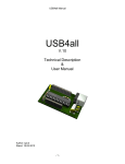
Rs4all Manual
RS4all
V.1
Technical Description
&
User Manual
Author: sprut
Stand: 03.04.2012
-1-
Rs4all Manual
1 Table Of Content
1
2
3
4
5
6
Table Of Content ..........................................................................................................2
List Of Figures ..............................................................................................................4
Terms Of Use: ..............................................................................................................5
About this Document ....................................................................................................5
Introduction...................................................................................................................5
Hardware ......................................................................................................................6
6.1 Type of PIC-Microcontroller.....................................................................................6
6.2 RS232-Interface to the PC ......................................................................................7
6.3 Microcontroller clock source....................................................................................8
6.4 Power supply...........................................................................................................8
6.5 Usable Interfaces ....................................................................................................9
6.5.1
Interfaces with 28-pin Controll PIC .................................................................9
6.5.2
Interfaces with 40/44-pin Controll PIC ..........................................................10
6.5.3
Output Pins ...................................................................................................11
6.5.4
Input Pins......................................................................................................11
6.6 TTL-IO-Port-Pins...................................................................................................11
6.7 ADC-Input .............................................................................................................11
6.8 Frequency Counter Input.......................................................................................11
6.9 RS232-Interface ....................................................................................................12
6.10
I2C-Interface .....................................................................................................12
6.11
Dot-Matrix LCD-Interface ..................................................................................12
6.12
PWM-Output .....................................................................................................12
6.13
Stepper Motor Output .......................................................................................12
6.14
Model-Servo-Output..........................................................................................12
7 Software .....................................................................................................................13
7.1 PC .........................................................................................................................13
8 List of Commands.......................................................................................................14
8.1 TTL-IO-Pins...........................................................................................................15
8.2 10-Bit / 12-Bit-ADC................................................................................................15
8.3 Frequency Counter ...............................................................................................15
8.4 RS-232 ..................................................................................................................15
8.5 I2C-Interface .........................................................................................................15
8.6 SPI-Interface .........................................................................................................15
8.7 Microwire...............................................................................................................15
8.8 Shift-Register Interface .........................................................................................15
8.9 LCD-Interface........................................................................................................15
8.10
PWM1 und PWM2 ............................................................................................16
8.11
Internal EEPROM .............................................................................................16
8.12
Stepper-Motor-Interfaces ..................................................................................16
8.12.1 Stepper-Motor-Interface with ABCD-phases.................................................16
8.12.2 L297-Stepper-Motor-Interface.......................................................................16
8.13
Servos...............................................................................................................16
8.14
Impulse Counter................................................................................................16
8.15
Reset the Rs4all................................................................................................17
9 How to Control the Rs4all ...........................................................................................18
9.1 Example Code to use Rs4all .................................................................................19
9.1.1
Example: Write one byte into the EEPROM..................................................19
-2-
USB4all Handbuch
9.1.2
9.1.3
9.1.4
9.1.5
9.1.6
9.1.7
Example: Measure a Voltage........................................................................19
Example: Measure the Frequency ................................................................20
Example: Write “Hallo” to the LCD-Display ...................................................20
Example: Switch on an LED at Pin RC0 .......................................................20
Example: Turn Stepper-Motors.....................................................................20
Example: Measure the Temperature with LM75 via I2C ...............................20
-3-
USB4all Handbuch
2 List Of Figures
Figure 1 Rs4all - overview ...................................................................................................6
Figure 2 RS-232-Interface with driver ..................................................................................7
Figure 3 RS-232-Interface without driver .............................................................................8
Figure 4 Pinout of the PIC18F2455 / 2550 / 2458 / 2553...................................................10
Figure 5 Pinout of the PIC18F4455 / 4550 / 4458 / 4553...................................................11
-4-
Rs4all Manual
3 Terms Of Use:
THIS SOFTWARE CAN BE USED WITHOUT PAYING ANY LICENCE FEE FOR
PRIVATE AND COMMERCIAL USE. THIS IS BETA-SOFTWARE. IF THE SOFTWARE
HAS LEFT BETA TEST, IT WILL BE PUBLISHED UNDER GPL-LICENCE.
THERE IS NO WARRANTY FOR THE PROGRAM, TO THE EXTENT PERMITTED BY
APPLICABLE LAW. EXCEPT WHEN OTHERWISE STATED IN WRITING THE
COPYRIGHT HOLDERS AND/OR OTHER PARTIES PROVIDE THE PROGRAM “AS IS”
WITHOUT WARRANTY OF ANY KIND, EITHER EXPRESSED OR IMPLIED,
INCLUDING, BUT NOT LIMITED TO, THE IMPLIED WARRANTIES OF
MERCHANTABILITY AND FITNESS FOR A PARTICULAR PURPOSE. THE ENTIRE
RISK AS TO THE QUALITY AND PERFORMANCE OF THE PROGRAM IS WITH YOU.
SHOULD THE PROGRAM PROVE DEFECTIVE, YOU ASSUME THE COST OF ALL
NECESSARY SERVICING, REPAIR OR CORRECTION.
4 About this Document
The Rs4all is based on the USB4all-CDC. The most of the interfaces and control
commands atre identical. Because of this, the primary document for the Rs4all ist the
handbook of the USB4all.
This Rs4all-handbook only describes the differences between Rs4all and USB4all. These
are:
• Different interface to the PC (RS232 instead of USB)
• Separate 5V-power-supply
• SPI is not supported
• Microwire is not supportet
• RS232 is used for communication with the PC and can not be used for anything
else
• Only 3 ABCD-phases-stepper-motor interfaces (instead of 4)
• 2 digital IO-pins less
• 2 model-servos less
• Shift-register interface is using an other outout-pin
• Other frequencies for the both PWM-outputs
5 Introduction
The Rs4all s an easily usable solution to connect a simple (e.g. self made) device to the
PC via RS232-interface. It is a PIC-microcontroller from Microchip (e.g. PIC18F2455) with
a special firmware.
-5-
Rs4all Manual
Figure 1 Rs4all - overview
The Rs4all is controlled via a RS232-port.
Rs4all offers to the user the following connectivity:
•
•
•
•
•
•
•
•
•
•
•
•
18 or 29 digital Input/Output Pins (TTL)
10 analogue ADC-inputs (0..5V) with 10 or 12 bits resolution
1 frequency counter (up to 50 MHz)
one I2C-Master-interface
one shift-register-interface
interface for 2 LCD-dot-matrix-displays
2 PWM-Outputs
3 stepper motor interfaces for ABCD-phase-connections
4 stepper motor interfaces for L297-circuits
Connections for 11 model-servos.
2 impulse-counter-inputs
192 Byte internal EEPROM-memory
6 Hardware
6.1
Type of PIC-Microcontroller
Rs4all is by default a PIC18F2455 microcontroller with special firmware. Instead of the
PIC18F2455 another type can be used. The following table lists the possible types and the
resulting number of digital IO-pins and the ADC resolution:
-6-
Rs4all Manual
PIC-Type
PIC18F2455 / PIC18F2550
PIC18F4455 / PIC18F 4550
PIC18F2458 / PIC18F 2553
PIC18F4458 / PIC18F 4553
Number of digital IO-Pins
20
31
20
31
ADC resolution
10 bit
10 bit
12 bit
12 bit
++Information++
In several figures of this document a PIC18F2550 is shown. However, it can be used a
PIC18F2455 in all circuitries.
The 28-pin-firmware works without any modification is PIC18F4455/4550/4458/4553 (40 or
44 pins), but their additional pins are not used and their pin numbers are not identical to
the pin numbers in the schematics of this document.
The 40-pin-firmware can use 11 additional digital IO-Pins. But the pin numbers are not
identical to the pin numbers in the schematics of this document.
6.2
RS232-Interface to the PC
The RS4all is connected to the PC via an RS232-interface. The RS232-pins of the
microcontroller generate and expect TTL-level-signals. These signals have to be inverted
and amplified by an external RS232-driver circuit. The following figure shows the typical
connections between microcontroller, driver-IC and RS232-connector.
Figure 2 RS-232-Interface with driver
If the serial cable between Rs4all and PC is not very long, then the driver-IC may not be
necessary. Many PC-motherboards will accept TTL-level-signals at the RS-232-Ports. A
serial resistor in the receive-line of the Rs232 will prevent the microcontroller from being
damaged by to high voltage levels.
Depending on the presence of the driver-IC the microcontroller has to operate with normal
or inverse polarity at the RS232-interface-pins. This is controlled by the voltage level at the
RC4-pin (D-). This is pin 15 (28 pin housing) or pin 23 (40 pin housing) or pin 42 (44 pin
housing). If a driver is used, then this pin has to be connected to ground (Vss). If no driver
is used, then this pin has to be connected with +5V (Vdd).
-7-
Rs4all Manual
Figure 3 RS-232-Interface without driver
6.3
Microcontroller clock source
The Rs4all is by default clocked by an internal 8 MHz oszillator. The oszillator is calibrated
und should have an error of less then 1% under normal conditions. Depending on the
environmental temperature, the error of the oszillator can become larger:
• +25°C
±2%
• -10°C to +85°C
±5%
• -40°C to +85°C
±10%
All clocks, the precision of the frequency counter and the RS232 baud rate depend on this
clock.
If the precision of the internal oszillator don’t meets the requirements, then an external 8MHz-crystal can be connected to the pins OSC1 and OSC2 (Pin 9 & 10). Two 22pF
capacitors have to be connected between these pins and Vss.
Rs4all will automatically use this crystal, if it is connected to the microcontroller at poweron.
6.4
Power supply
Rs4all needs 5V DC power. The function is guarantied from 4,2V up to 5,5V. The
microcontroller will not need more then 10 mA. Additional loads will of course need
additional current.
The result of the ADC measurement is only correct for a supply voltage of 5V. A larger or
smaller supply voltage will produce an errorous result, except an external reference
voltage is used. See the ADC-chapter for details.
-8-
Rs4all Manual
6.5
Usable Interfaces
Die following tables shows which pins are usable for what kind of interface function. One
can see, that some interfaces can not be used at the same time in parallel. Thus LCD1
can not be used in parallel to I2C, Motor1 or Motor2. But one can use ADC (the 5 inputs
AN0..AN4), the frequency counter, I2C, LCD2, PWM1 and PWM2 in parallel.
6.5.1 Interfaces with 28-pin Controll PIC
The PIC18F2455 / 2550 / 2458 / 2553 have 28 Pins.
Pin
IO-Port
ADC
FRQ
I2C
SR
2
RA0
AN0
3
RA1
AN1
B3
4
RA2
AN2
C3
5
RA3
AN3
6
RA4
7
RA5
10
RA6
21
RB0
AN12
SDA
SDI
22
RB1
AN10
SCL
SCL
23
RB2
AN8
RS
24
RB3
AN9
25
RB4
AN11
26
LCD
1
LCD
2
PWM
Motor
1..3
L297
1..4
Servo
Counter
A3
D3
FRQ
C1
AN4
E1
A1
CL1
SB0
B1
DIR1
SB1
RS
C2
CL2
SB2
R/W
R/W
D1
DIR2
SB3
D4
D4
A2
CL3
SB4
RB5
D5
D5
B2
DIR3
SB5
27
RB6
D6
D6
C2
CL4
SB6
28
RB7
D7
D7
D2
DIR4
SB7
11
RC0
12
RC1
13
RC2
E2
SDO
SC0
PWM2
SC1
PWM1
SC2
C3
These microcontrollers are available in 28-pin-DIL-housing (PDIP) and 28-pin SMDhousing (SOIC). The following figure shows the pinout.
-9-
Rs4all Manual
Figure 4 Pinout of the PIC18F2455 / 2550 / 2458 / 2553
6.5.2 Interfaces with 40/44-pin Controll PIC
The PIC18F4455 / 4550 / 4458 / 4553 have 40 or 44 Pins.
Pin
IO-Port
ADC
FRQ
2
RA0
AN0
3
RA1
AN1
B3
4
RA2
AN2
C3
5
RA3
AN3
6
RA4
7
RA5
14
RA6
33
RB0
AN12
SDA
SDI
34
RB1
AN10
SCL
SCL
35
RB2
AN8
RS
36
RB3
AN9
37
RB4
AN11
38
39
RS
232
I2C
SR
LCD
1
LCD
2
PWM
Motor
1..4
L297
1..4
Servo
A3
D3
FRQ
C1
AN4
A1
CL1
SB0
B1
DIR1
SB1
RS
C2
CL2
SB2
R/W
R/W
D1
DIR2
SB3
D4
D4
A2
CL3
SB4
RB5
D5
D5
B2
DIR3
SB5
RB6
D6
D6
C2
CL4
SB6
40
RB7
D7
D7
D2
DIR4
15
RC0
16
RC1
17
RC2
19
RD0
20
RD1
21
RD2
22
RD3
27
RD4
28
RD5
29
RD6
30
RD7
8
RE0
Counter
E1
E2
SDO
- 10 -
SB7
SC0
PWM2
SC1
PWM1
SC2
C3
Rs4all Manual
9
RE1
10
RE2
These microcontrollers are available in 40-pin-DIL-housing (PDIP) and 44-pin SMDhousing (SOIC, TQFP or QFN). The following figure shows the 40-pin-pinout.
Figure 5 Pinout of the PIC18F4455 / 4550 / 4458 / 4553
6.5.3 Output Pins
See the USB4all handbook.
6.5.4 Input Pins
See the USB4all handbook.
6.6
TTL-IO-Port-Pins
See the USB4all handbook.
6.7
ADC-Input
See the USB4all handbook.
6.8
Frequency Counter Input
See the USB4all handbook.
The precision of the frequency counter depends on the precision of the microcontroller’s
clock source. If no crystal is connected to the microcontroller, then an internal oszillator is
used. The precision of this internal oscillatior depends on environmental temperature
and power supply level.
• +25°C
±2%
• -10°C to +85°C
±5%
- 11 -
Rs4all Manual
•
-40°C to +85°C
±10%
If an 8-MHz-crystal is connected to the pins OSC1 and OSC2, then this crystal will be
used by the microcontroller. In this situation the precision of the counter depends on the
precision of the crystal. Standard crystals have errors of ±30 … ±50 ppm.
The frequency counter has a small additional systematic error.
In automatic mode this error is
• +20 ppm.
In manual mode the error depends on the selected counting interval.
• 1 ms
not tested
• 10 ms
+0.2%
• 100 ms
+60 ppm
6.9
RS232-Interface
The RS232-interface is used for the communication with the PC, and can not be
used for anything else.
6.10
I2C-Interface
See the USB4all handbook.
6.11
Dot-Matrix LCD-Interface
See the USB4all handbook.
6.12
PWM-Output
See the USB4all handbook.
6.13
Stepper Motor Output
See the USB4all handbook.
6.14
Model-Servo-Output
See the USB4all handbook.
- 12 -
Rs4all Manual
7 Software
7.1
PC
The RS4all has to be connected to a RS232-port of the PC (e.g. COM1). The COM-port
has to be set to:
• Baud rate
9600
• Data bits
8
• Stop bits
1
• Parity
none
• Flow control none
The low baud rate was selected to guarantie a reliable communication via long RS232cables. At 9600 baud a distance of 150 meters (5600 feet) is possible.
- 13 -
Rs4all Manual
8 List of Commands
The Rs4all is controlled by commands. Every command is a short string of bytes. The
string is send via RS232 to the Rs4all, the device works off this command and sends back
a report. This report is a string of 16 bytes.
The length of the command string can not exceed 20 bytes. However, the most commands
need only 2 … 4 bytes.
For the Rs4all the bytes of the command string have to be converted into an ASCII-string.
This text-string is 3 times longer then the byte string. This text string doesn’t has to exceed
a length of 64 bytes! This limits the number of command-bytes for the Rs4all to 20 only.
If e.g. the bytes 0x55, 0x01, 0x02, 0x16 have to be sent to the Rs4all, then the bytes have
to be convertet into the following ASCII-string: ‘#55-01-02-16’+0x00
The string starts with the ‘#’-sybol, then follow the bytes as hexadezimal values. The bytes
have to be separated by ‘-‘-sybols. At the end of the string follows 0x0A, 0x0D or 0x00. In
the exaple I used 0x00 (zero terminated string), but if one is using a terminal program to
control the Rs4all, then the Enter-Key (0x0D) will do the job too.
The first byte is addressing the subsystem of Rs4all, which will receive and work off the
command (e.g. PWM or ADC). The following subsystems exist:
•
•
•
•
•
•
•
•
•
•
•
•
•
•
•
•
•
•
•
•
•
•
0x50
0x51
0x52
0x54
0x55
0x56
0x57
0x58
0x5A
0x5D
0x5E
0x5F
0x60
0x61
0x62
0x63
0x64
0x65
0x66
0x68
0x69
0xFF
TTL-IO-Pins
10-Bit-ADC
frequency counter
I2C-Interface
Dot-matrix-LCD-Display Nr. 1
Dot-matrix-LCD-Display Nr. 2
PWM-output 1
PWM-output 2
internal EEPROM
ABCD-stepper-motor Nr. 1
ABCD-stepper-motor Nr. 2
ABCD-stepper-motor Nr. 3
L297 stepper-motor Nr. 1
L297 stepper-motor Nr. 2
L297 stepper-motor Nr. 3
L297 stepper-motor Nr. 4
model-servo-channel B
model-servo-channel C
Shift register
Counter 0
Counter 3
Reset
The second byte contains the command. For the most subsystems this byte has the
following meaning:
•
0x00
deactivate the subsystems
- 14 -
Rs4all Manual
•
•
•
•
•
0x01
0x02
0x03
0x04
0x05
initiate the subsystems
send one byte
read one byte
send a string of bytes
receive a string of bytes
If additional data is needed, then it will follow starting with the 3d byte.
8.1
TTL-IO-Pins
See the USB4all handbook.
The 18 IO-pins are organized in 3 ports:
• PortA contains 7 pins: RA0..RA6
• PortB contains 8 pins: RB0..RB7
• PortC contains 3 pins: RC0..RC2
8.2
10-Bit / 12-Bit-ADC
See the USB4all handbook.
8.3
Frequency Counter
See the USB4all handbook.
8.4
RS-232
This interface can not be used, because it is needed for communication with the PC.
8.5
I2C-Interface
See the USB4all handbook.
8.6
SPI-Interface
Can not be used.
8.7
Microwire
Can not be used.
8.8
Shift-Register Interface
See the USB4all handbook.
In comparison with USB4all, a different pin is used as shift register outout.
The shift-registers-interface is using the following 3 pins of PortB:
• SDO = RC1
• SDI = RB0
• SCK = RB1
8.9
LCD-Interface
See the USB4all handbook.
- 15 -
Rs4all Manual
8.10
PWM1 und PWM2
See the USB4all handbook.
The PWM-circuitries of Rs4all use other frequencies then USB4all.
There are 3 commands for every PWM-channel:
Subsystem
0x57 / 0x58
PWM1 / PWM2
Command
0x00
Off
0x01
Initiate
0x02
Set dutycycle
Byte 2
-
Byte 3
-
Byte 4
-
0: 8 kHz / 256
1: 80 kHz / 100
2: 20 kHz / 100
3: 5 kHz / 100
4: 31 kHz / 256
5: 8 kHz / 256
6: 2 kHz / 256
7: 8 kHz / 1024
8: 2 kHz / 1024
9: 488 Hz / 1024
Lower 8 Bits
-
-
Upper 2 Bit-
-
For all commands the USB4all replies with 16 byte nonsense data.
8.11
Internal EEPROM
See the USB4all handbook.
8.12
Stepper-Motor-Interfaces
See the USB4all handbook.
8.12.1
Stepper-Motor-Interface with ABCD-phases
See the USB4all handbook.
This device supports only 3 Interfaces with ABCD-phases. The interface number 4 is
not supported.
8.12.2
L297-Stepper-Motor-Interface
See the USB4all-Handbook.
8.13
Servos
See the USB4all-Handbook.
The group Servo-B is identical to USB4all, but the group Servo-C contains only 3
outputs (SC0, SC1, SC2). The outputs SC6 and SC7 are not supported.
8.14
Impulse Counter
See the USB4all handbook.
- 16 -
Rs4all Manual
8.15
Reset the Rs4all
Rs4all can be reseted into the power-up-state with this command.
Subsystem
0xFF
RESET
Befehl
-
Byte 2
-
Byte 3
-
Rs4all will NOT send any reply to the PC.
- 17 -
Byte 4
-
Byte 5
-
Rs4all Manual
9 How to Control the Rs4all
The Rs4all is controlled by ASCII-string received via RS232-interface. Nearly every
programming language should support communication via RS232 (COM-ports). Even
terminal programmes (HyperTerminal, Putty…) can be used.
Every command-string starts with the prefix “#’. Then follow the bytes. Every byte is a 2
digit long hexadezinmal number. The individual bytes are interspaced by”-“ symbols. At the
end has to follow a byte with the value 0x0D (begin of line) or 0x0A (next line) or 0x00
(zero terminated).
The whole ASCII-string doesn’t has to be longer then 64 symbols. Consequently it can not
contain more then 20 bytes.
Example:
To initiate the 1st LCD the following 4 bytes have to be send to the Rs4all:
0x55, 0x01, 0x02, 0x16
The correct formatted string looks like this:
‘#55-01-02-16’+0x00
The”0x00” at the end stands for a byte 00, the string is zero terminated. Instaed of 0x00 it
would be possible to use 0x0D (enter) or 0x0A.
As spacer between the bytes I used the “-“-symbol. Practically any symbol can be used as
spacer, except #,0,1,2,3,4,5,6,7,8,9,a,b,c,d,e,f,A,B,C,D,E,F.
Instaed of ’01’ it is possible to write ‘1’. Leading zeros can be removed.
The following Delphi/Pascal-Code converts 16 bytes (stored in send_buf) into an ASCIIstring and sends it to Rs4all (by the function Comport1.WriteStr)
var
k
asciistr
send_buf
: integer;
: string;
: array[0..15] of byte;
.
.
.
asciistr :='#';
for k:=0 to 15 do asciistr := asciistr + inttohex(send_buf[k],2)+'-';
asciistr := asciistr + chr($0d);
Comport1.WriteStr(asciistr);
The Rs4all will answer for every command (excep reset) with an ASCII-string. The prefix is
a ‘@’, the separator is ‘-‘ and at the end follow the 3 bytes 0x0A,0x0D,0x00.
The string contains 16 numbers, every number is written as a 2 digit long hexadezimal
number. All letters are upper-case letters.
All this adds up to a length of 50 bytes.
The following Delphi/Pascal-code extracts the 16 bytes from a received string:
- 18 -
Rs4all Manual
//Helper-function: convert ASCII-Symbold into numbers
//would be simpler with ORD-function
function asciiwert(ch:char):integer;
begin
result:=0;
case ch of
'1': result:=1;
'2': result:=2;
'3': result:=3;
'4': result:=4;
'5': result:=5;
'6': result:=6;
'7': result:=7;
'8': result:=8;
'9': result:=9;
'A': result:=10;
'B': result:=11;
'C': result:=12;
'D': result:=13;
'E': result:=14;
'F': result:=15;
end;
end;
.
.
.
var
nrrx
: integer;
k
: integer;
rxstr
: string;
receive_buf : array[0..63] of byte;
.
.
.
//receive via COM-port with ReadStr(var Str: String; Count: Integer): Integer;
nrrx:=Comport1.ReadStr(rxstr, 50);
for k:=0 to (nrrx div 3)-1 do begin
receive_buf[k]:=asciiwert(rxstr[3*k+2])*16 + asciiwert(rxstr[3*k+3]);
end;
.
.
.
9.1
Example Code to use Rs4all
These are some examples for the use of Rs4all. All code-examples are written in
Delphi/Pascal.
9.1.1 Example: Write one byte into the EEPROM
This code writes the value 0x55 into the EEPROM-cell with address 0x00.
Comport1.WriteStr(‘#5A-2-0-55’+chr(0));
Comport1.ReadStr(rxstr, 50);
// EEPROM
// Reply
9.1.2 Example: Measure a Voltage
This code initiated the ADC with inputs AN0 .. AN3 and measures the voltage at pin AN2.
Comport1.WriteStr(‘#51-1-4-0’+chr(0));
Comport1.ReadStr(rxstr, 50);
- 19 -
// initiate
// Reply
Rs4all Manual
Comport1.WriteStr(‘#51-2-2’+chr(0));
Comport1.ReadStr(rxstr, 50);
// set AN2
// Reply
Comport1.WriteStr(‘#51-3’+chr(0));
Comport1.ReadStr(rxstr, 50);
// measure voltage
// Reply with result
9.1.3 Example: Measure the Frequency
This code measures the frequency at pin RA4.
Comport1.WriteStr(‘#52-5’+chr(0));
Comport1.ReadStr(rxstr, 50);
// measure the frequency
// Reply with result
9.1.4 Example: Write “Hallo” to the LCD-Display
This code initiates the LCD-Display and writes ”Hallo” on the display:
Comport1.WriteStr(‘#55-1-2-10’+chr(0));
Comport1.ReadStr(rxstr, 50);
// initiate
// Reply
Comport1.WriteStr(‘#55-4-5-48-61-6c-6c-6f’+chr(0));
Comport1.ReadStr(rxstr, 50);
// Reply
// Hallo
9.1.5 Example: Switch on an LED at Pin RC0
This code switches the pin RC0 into output mode and sets this pin to “high” leve:
Comport1.WriteStr(‘#50-5-0-0-1’+chr(0));
Comport1.ReadStr(rxstr, 50);
// RC0 becomes output
// Reply
Comport1.WriteStr(‘#50-6-0-0-1’+chr(0));
Comport1.ReadStr(rxstr, 50);
// switch RC0 to high-level
// Reply
9.1.6 Example: Turn Stepper-Motors
This code initiates the 2nd ABCD-phase-stepper motor interface and turns the motor 10000
half-steps CCW..
Comport1.WriteStr(‘#5E-1’+chr(0));
Comport1.ReadStr(rxstr, 50);
// initiate
// Reply
Comport1.WriteStr(‘#5E-2-10-27-1-0’+chr(0));
Comport1.ReadStr(rxstr, 50);
// turn
// Reply
//es fehlt hier noch die Warteschleife, falls man warten möchte
9.1.7 Example: Measure the Temperature with LM75 via I2C
This code initiates the I2C-bus and reads the temperature from a LM75-sensor chip at this
bus.
- 20 -
Rs4all Manual
Comport1.WriteStr(‘#54-1-0-0’+chr(0));
Comport1.ReadStr(rxstr, 50);
// on Master 100kHz
// Reply
Comport1.WriteStr(‘#54-3-48-2’+chr(0));
Comport1.ReadStr(rxstr, 50);
// read temperature
// Reply with temperature
- 21 -