1
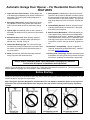
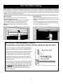
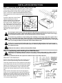
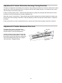
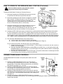
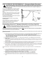
TM
OWNER INSTALLATION AND
USER MANUAL Series 3000
Models 3214, 3314, 3316 & 3414
Automatic Garage Door Opener
For Sectional Overhead Residential Doors Only
DO NOT USE ON ONE PIECE DOORS
Before Starting Installation Read all Instructions Thoroughly
to Familiarize Yourself with All Aspects of Installation and Adjustment!
DOOR AND OPENER WILL NOT OPERATE PROPERLY UNTIL INFRARED SAFETY
SENSORS ARE INSTALLED AND PROPERLY ADJUSTED! DO NOT OPERATE DOOR
OPENER UNTIL FULLY INSTALLED, ADJUSTED & INSTRUCTED TO DO SO!
CONTENTS
Installation… . . . . . . . . . . . . . . . .
Features… … … … … … . .
Door Tests… … … . . . . . . . . . .
Pre-Assembly Check… … … … .
Installation Instructions… … … …
Installing Wall Station… … … . …
Install Infrared Safety Sensors… … .
Wall Station Code Change
and Programming… … … … .
Infrared Safety Sensors Alignment
Transmitter Code Change & Programming
Travel Adjustment… … … … …
Obstruction Sensing Test… … . . .
Infrared Safety Sensor Obstruction Test.
© Copyright 2003 Wayne-Dalton Corp.
2
4
5
5
6
8
9
14
16
16
19
18
19
Wireless Keyless Entry Installation. . . . .
Opening & Closing Force Adjustment…
Contact Obstruction Sensing Adjustment.
Mechanical lock Adjustment. . . . . . . . .
Operational Safety Rules… … …
Operation on Your Opener… … … .
Emergency Release Disconnect. . . . . .
Maintenance Schedule… … … . . .
Trouble Shooting… … … … …
Parts Breakdown-Rail Assembly… …
Parts Breakdown-Power Head Assembly.
Accessories… … … … … . . .
Warranty.… … … … … . . . . .
Part No: 307545
New
20
21
22
22
23
24
26
27
28
29
30
31
32
6/18/2003
Read These Important Safety Rules Before Proceeding
This symbol indicates caution and appears throughout this instruction
manual. This garage door opener is designed and tested to offer reasonably safe operation if installation is followed in strict accordance with these
safety instructions. Failure to comply with these instructions may result in
serious personal injury or property damage.
IMPORTANT INSTALLATION INSTRUCTIONS
WARNING: To reduce the risk of severe injury of death:
READ AND FOLLOW ALL INSTALLATION INSTRUCTIONS.
Do not connect opener to source of power until
instructed to do so.
Install only on a properly balanced garage door.
An improperly balanced door could cause severe
injury. Have a qualified service person make repairs to cables, spring assemblies and other
hardware before installing opener.
Installation and wiring must comply with local
building and electrical codes. Connect the power
cord to a properly grounded outlet. Do not remove round ground pin from power cord.
To reduce the risk of injury to persons, use this
operator only with sectional overhead doors.
Fiberglass, aluminum and steel doors must be reinforced to prevent damage to the door. Check
with your garage door manufacturer for their recommendations.
Remove all ropes and remove or make inoperative
all locks connected to the garage door before installing opener.
Do not use sensitivity adjustments to compensate
for a poorly operating door. This will interfere
with the proper operation of the safety reverse
mechanism and may damage the door.
Locate control button: within sight of door, at a
minimum height of 5 feet, so small children cannot reach it, and away from all moving parts of the
door.
Install entrapment warning label next to control
button in a prominent location, such as the inside
of the garage door, or as instructed in the installation instructions. If label adhesive will not adhere
to the surface, secure the label by additional mechanical means such as staples, nails or screws.
If necessary, use an intermediate mounting surface, such as plywood, cut to the appropriate size.
Install Emergency Release tag to the emergency
red cord.
After installing opener, the door must reverse
when it contacts a 1 inch high solid test object on
the floor.
Open door must not close and closing door must
open if photoelectric system in obstructed by 6” x
12” object, using test procedure described in Step
30.
Do not wear rings, watches or loose clothing
when installing or servicing a garage door system. Use a sturdy, non-metallic step ladder.
If possible, install door opener 7 feet or more
above floor. Mount the emergency release knob 6
feet above the floor.
AFTER INSTALLATION IS COMPLETE, FASTEN THIS MANUAL NEAR GARAGE DOOR.
PERFORM PERIODIC SAFETY CHECKS, MAINTENANCE AND ADJUSTMENTS, AS RECOMMENDED.
NOTE: This equipment has been tested and found to comply with the limits for a Class B digital device, pursuant to Part 15 of the FCC Rules.
These limits are designed to provide reasonable protection against harmful interference in a residential installation. This equipment generates uses and can radiate radio frequency energy and, if not installed and used in accordance with the instructions, may cause harmful interference to radio communications. However, there is no guarantee that interference will not occur in a particular installation. If this equipment
does cause harmful interference to radio or television reception, which can be determined by turning the equipment off and on, the user is
encouraged to try to correct the interference by one or more of the following measures: Reorient or relocate the receiving antenna. Increase
the separation between the equipment and receiver. Connect the equipment into an outlet on a circuit different from that to which the receiver
is connected. Consult the dealer or an experienced radio/TV technician for help. Warning: Changes or modifications to this unit not expressly approved by Wayne-Dalton Corp. could void the user’s authority to operate the equipment.
FCC Regulatory Information: This device complies with Part 15 of the FCC Rules. Operation is subject to the following two conditions: (1)
this device may not cause harmful interference, and (2) this device must accept any interference received, including interference that may
cause undesired operation.
IC Regulatory Information: This Class B digital apparatus meets all requirements of the Canadian Interference Causing Equipment Regulations. Operation is subject to the following two conditions: (1) this device may not cause harmful interference, and (2) this device must accept any interference received, including interference that may cause undesired operation.
2
Veuillez lire ces règles de sécurité importantes avant de commencer les travaux
Ce symbole vous demande de prendre les précautions voulues. Vous le trouverez d’un bout à
l’autre du présent guide d’installation. Cet ouvre porte de garage a été conçu et essaye pour
vous offrir un fonctionnement sécuritaire dans la mesure ou les directives d’installation sont
respectées conformément a ces mesures de sécurité. Le non respect de ces mesures de
sécurité risqué d’entraîner des blessures corporelles graves et des dommages matériel.
IMPORTANT —NOTICE D’INSTALLATION—
AVERTISSEMENT –POUR REDUIRE LES RISQUES DE BLESSURES MORTELLES
APPOSEZ L’ÉTIQUETTE DE MISE EN GARDE RELATIVE AU DANGER DE HAPPEMENT À PROXIMITE
DU BOUTON DE COMMANDE ET L’ÉTIQUETTE RELATIVE AU RÉGLAGE DE LA COMMANCE Á UN
EMPLACEMENT EN EVIDENCE—PAR EXEMPLE
SUR LA PAROI INTÉRIEURE DE LA PORTE DE GARAGE OU SELON LES INSTRUCTIONS DE LA NOTICE D’INSTALLATION. APPOSEZ L’ÉTIQUETTE
RELATIVE AU DÉSACCOUPLEMENT D’URGENCE
SUR LE DISPOSITIF OU À PROXIMITE DE CE DERNIER.
LISEZ CETTE NOTICE ET CONFORMEZ-VOUS AUX
INSTRUCTIONS.
NE POSEZ CET OUVRE-PORTE QUE SUR UNE
PORTE DE GARAGE CORRECTEMENT ÉQUILIBRÉE. UNE PORTE MAL ÉQUILIBRÉE PEUT CAUSER DES BLESSURES GRAVES. CONFIEZ LA REPARATION DES CABLES, DES RESSORTS, ET DE
TOUT AUTRE ÉLÉMENT À UN TECHNICIEN QUALIFIÉ AVANT D’ENTREPRENDRE L’INSTALLATION.
POUR RÉDUIRE LE RISQUE DE BLESSURES CORPORELLES, UTILISER CET OUVRE-PORTE POUR
DES PORTES BASCULANTES SECTIONNELLES
UNIQUEMENT.
NE BRANCHEZ PAS L’OUVRE-PORTE AVANT D’Y
ÊTRE AUTORISÉ PAR LA NOTICE.
UNE FOIS L’OUVRE-PORTE INSTALLÉ, LES SENS
DE LA COURSE DOIT S’INVERSER LORSQUE LA
PORTE ENTRE EN CONTACT AVEC UN OBJET
D’UNE HAUTEUR DE 25.4MM (1 PO) POSE SUR LE
SOL.
LES PORTES EN FIBRE DE VERRE, EN ALUMINUM
ET EN ACIER DOIVENT ETRE RENFORCÉES POUR
EVITER D’ENDOMMAGER LA PORTE. CONSULTEZ
LE FABRICANT DE VOTRE PORTE DE GARAGE
POUR OBTENIR SES RECOMMANDATIONS.
L’INSTALLATION ET LE BRANCHEMENT ÉLECTRIQUE DOIVENT ÊTRE CONFORMES AUX CODES
LOCAUX DU BÂTIMENT ET DE L’ÉLECTRICITÉ
RACCORDER LE CORDON D’ALIMENTATION Á
UNE PRISE ADÉQUATEMENT MISE Á LA TERRE.
NE PAS ENLEVER LA BRANCHE RONDE DE MISE Á
LA TERRE DU CORDON D’ALIMENTATION.
ENLEVEZ LES CORDES ET ENLEVEZ OU NEUTRALISEZ TOUT DISPOSITIF DE VERROUILLAGE SOLIDAIRE DE LA PORTE DE GARAGE AVANT
L’INSTALLATION.
NE VOUS SERVEZ PAS DES RÉGLAGES DE LA
SENSIBILITÉ POUR COMPENSER LE MAUVAIS
FONCTIONNEMENT D’UNE PORTE. CECI POURRAIT FAIRE OBSTACLE AU BON FONCTIONNEMENT DU MÉCANISME DE L’INVERSEUR DE SÉCURITÉ ET POURRAIT ENDOMMAGER LA PORTE.,
SI LE SYSTÈME PHOTOÉLECTRIQUE EST BLOQUÉ
PAR UN OBJET DE PLUS DE 6 PO X 12 PO, LA
PORTE OUVERTE NE DOIT PAS SE FERMER ET LA
PORTE SE FERMANT DOIT S’OUVRIR. VÉRIFIER
CELA EN UTILISANT LA VÉRIFICATION DÉCRITE Á
L’ÉTAPE 20.
DANS LA MESURE DU POSSIBLE, INSTALLEZ
L’OUVRE-PORTE Á AU MOINS 2.14M (7PI) DU SOL.
POSEZ LE DISPOSITIF DE DÉSACCOUPLEMENT
D’URGENCE Á 1.83 M (6 PI) DU SOL.
NE PAS PORTER DES BAGUES, DES MONTRES OU
DES VÊTEMENTS LÂCHES PENDANT
L’INSTALLATION OU LA VERIFICATION TECHNIQUE DU SYSTÈME DE PORTE DE GARAGE. UTILISER UNE ÉCHELLE NON MÉTALLIQUE STABLE.
INSTALLEZ LE BOUTON DE COMMANDE Á UN ENDROIT QUE L’ON PEUT VOIR DE L’EMBRASURE DE
LA PORTE, À UNE HAUTEUR MINIMALE DE 1.53 M
(5 PI) DU SOL –AFIN QUE LES JEUNES ENFANTS
NE PUISSENT PAS L’ATTEINDRE—ET À L’ENCART
DES PIECES MOBILES DE LA PORTE.
CONSERVEZ CES INSTRUCTIONS.
APRÈS L’INSTALLATION, PLACER CE MANUEL À PROXIMITÉ DE LA PORTE DE GARAGE FAIRE RÉGULIÈREMENT LES VÉRIFICATIONS RECOMMANDÉES CONCERNANT LA SÉCURITÉ L’ENTRETIEN
ET LES RÉGLAGES
"Cet appareillage numérique de la classe B répond à toutes les exigences de l’interférence canadienne causant des règlements
d’équipement. Ľopération est sujette aux deux conditions suivantes: (1) cet dispositif peut ne pas causer l’interférence nocive, et (2) ce dispositif doit accepter n’importe quelle interférence reçue, y compris l’interférence qui peut causer l’opération peu désirée. "
3
Automatic Garage Door Opener – For Residential Doors Only
FEATURES
7. Safety System: Independent up and down force adjustments. When properly adjusted, the safety system
will automatically reverse when obstructed in down direction and return to fully open position. The door will
stop when obstructed in the up direction. See Adj. #2,
pg 22.
1. Open and Close Cycle Control: Allows garage door
to be started and stopped by push button, transmitter or
wall station. The next impulse sends garage door in
opposite direction.
2. Emergency Disconnect: Manual disconnect permitting operation of door during power failure with automatic reconnect when opener is reactivated. See pg
26.
8. Infrared Safety Sensors: Wired or wireless infrared
reversing sensors detect an obstruction in door path
and react by reversing door.
3. Opener light: Automatically turns on when opener is
activated and remains on for 4 minutes for convenience
and safety.
9. Multi-Function Wall Station: Wired wall station provides up/down door motion control and independent
overhead light on/off control. Wireless wall station provides up/down door motion control, independent overhead light on/off control, door down delay, adjustable
“pet position” function, and “pet position” program button.
4. Mechanical Door Lock: When properly adjusted,
opener locks door in closed position preventing unwanted entry. See Adj. # 3 pg 22.
5. Obstruction Warning Light: The convenience light
will flash after sensing an obstruction in the down direction and/or if the safety system malfunctions while in
the open position.
10. Homelink™ Compatibility: Opener is capable of
“learning” automobile equipped Homelink™ transceivers. Visit: www.homelink.com.
6. Motor: Permanently lubricated, thermally protected,
heavy duty motor with automatic reset.
11. Rolling Code Technology: Wireless transmitters and
wall stations use rolling code which prevents would-be
thieves from “grabbing” the transmitter’s digital code.
Before Starting Installation Read These Instructions Thoroughly to Familiarize
Yourself with All Aspects of Installation and Adjustment!
Caution: If your garage has no service entrance door, install optional outside quick release lock. This accessory allows
manual operation of garage door from outside in case of power failure.
Before Starting
Identify the door referring to illustrations below and verify that the door type is a sectional door with curved track. Do not
install if the door is any type of one piece door.
Note: The opener has been designed for sectional doors. Do not attempt to install this opener on any style one
piece door. Use of the enclosed opener on a one-piece door may result in serious personal injury of property
damage.
4
Door Tests Before Starting
Before you begin, complete the following two tests to insure that the door is balanced and working properly. A door that
binds, sticks or is out of balance could cause severe injury. Do not attempt to compensate for an improperly adjusted door
by the installation of an opener. This will interfere with the proper operation of the opener mechanism and/or may damage
the door. Have a qualified service person make any needed adjustments or repairs to cables, spring assemblies and other
hardware before proceeding with installation.
Door Test One
Door Test Two
Raise and lower the door and check closely for any
sticking or binding that occurs.
Lift the door approximately half way open, as illustrated.
When releasing the door, it should stay in position. If
spring pressure pulls the door further open or door
weight pulls it further down, your door is not properly
adjusted.
When properly installed, a door should remain clear of
the opening, when allowed to rest at its natural, full open
position.
If “door drift” pulls door back into opening or spring tension is not sufficient to pull door totally clear of opening,
the door is not properly adjusted.
IMPORTANT PRE-ASSEMBLY CHECK
If assembling a motor head unit from a factory sealed box skip this check.
Every Power Head Unit is factory tested and shipped with
the limit switch adjustment in the door CLOSED position.
If the Motor Power Head Unit has been powered up before
assembly, perform the following steps to insure that the
limit switch adjustment is in the door CLOSED position.
Connect Motor Head Unit to a power source and short
across the screw terminals labeled “PB” and “COM” with
a metal screw driver.
Motor should start; run through a full OPEN cycle, and stop.
This will leave Motor Power Head Unit in OPEN position.
To get Motor Power Head Unit back to full CLOSE position,
short and hold motor terminals again. Continue to short
terminals until Motor Power Head Unit stops in the
CLOSED position. Disconnect from power source and
proceed to assembly.
5
INSTALLATION INSTRUCTIONS
Step 1: Attaching Motor Power Head Unit to Rail
Before assembly, align sprocket/coupling cogs to match notches
of driver gear. Rotate the Motor Spline to position Driver Gear so
that the nearest notch in Driver Gear is directly behind Motor
Spline, as illustrated. Note: Do not rotate more than ½ turn.
Place opposite end of rail on temporary support approximately 6”
in height.
Proceed to attach rail to motor Power
Head Unit making sure that prealignment allows proper engagement
between sprocket/coupling cog and
driver gear notches. Realign as necessary, making sure to keep any rotation
only to the nearest notch. Using four (4)
supplied 1/4”-20 x 5/8” hex head bolts,
assemble Motor Power Head Unit to
rails with a 3/8” socket. Tighten securely.
Do not plug the opener power cord into electrical outlet until fully installed and instructed to do so in
this manual. Door springs, pulleys and cables are under extreme tension and can cause severe injury.
Do not attempt to adjust or repair. Call a professional door service company.
Do not wear rings, watches or loose clothing when installing or servicing a garage door system. Use a
sturdy, non-metallic step ladder. Remove all ropes or cords attached to the garage door. Failure to do
so may result in personal injury due to entanglement. Disable all existing locking devices on the garage
door, by securing lock/latch to inside face of door with suitable screw.
Install only on a properly balanced garage door. An improperly balanced door could cause severe injury. Have a qualified service person make repairs to cables, spring assemblies and other hardware before installing opener.
READ AND FOLLOW ALL INSTALLATION INSTRUCTIONS
Step 2: Positioning and Installing Front Wall Bracket
CAUTION: Do not attempt to loosen or remove any portion of door spring system in order to reinforce
header wall or to mount wall bracket. If these are necessary, call a professional garage door service
person.
Note: it is recommended that the door opener be installed 7 feet or more above the door.
REINFORCE THE HEADER WALL
Reinforce the header wall (wall above door opening) as required, to ensure rigid mounting of the front wall bracket.
Locate the vertical center line of the garage door and mark it
on the header above the door and on the top rail of the door.
Raise the door slightly until the top rail reaches the highest
point of travel (see illustration); using a carpenter’s level,
transfer and mark the highest point of travel on the header
wall.
Mount the front wall bracket with its lower edge approximately 1/2” (room permitting) above the mark showing the
highest point of travel centered on the vertical center line.
Mark the two mounting holes and pre-drill with a 3/16” drill.
Mount wall bracket using the lag screws supplied (1/4” x 11/2”) to ensure rigid mounting.
6
Step 3: Attach Unit to Front Wall Bracket
Raise the front end of the opener and attach it
to the front wall bracket, using the ¼” x 4” hex
head bolt and the supplied ¼” plastic insert
nut. Take care not to over tighten nut; tighten
only until end of bolt is flush with outside of
nut.
NOTE: If you have a torsion spring counterbalance system, it will be necessary to raise
the motor Head Assembly of the opener and
support it on a step-ladder to attach the front
end of the opener to Wall Bracket.
Step 4: Positioning the Motor End of Operator
To prevent damage to steel, aluminum, fiberglass or glass panel doors do not rest the opener of the
door without using a 2” x 4” at least 12” long.
Raise the motor end of the opener
and support it so you can open
the door to its fully open position.
You may need help raising motor
end if ladder is not high enough.
Open the door and place a 2” x 4”
piece of wood along the top section of the garage door. Rest the
double rails on the 2” x 4”, as illustrated.
Support the top section of the
door to prevent sagging.
Step 5: Mounting Motor End of Opener
Align the center of opener tracks with
the center line previously marked on
the top section of the garage door to
ensure rail will be parallel with the direction of door travel.
Use perforated hangers (cut as
needed to adjust length) from ceiling
or beams to hang opener at motor end
(be sure to locate and mount to solid
structural beams, as illustrated). Predrill with 3/16” drill bit and use 1/4” x
1-1/2” lag screws to ensure a rigid
mount.
Attach opener to hangers.
Do not use gear cap bolt or nut
for hanger attachment!
Note: Hanging brackets should be at an angle to provide rigid support. If hangers have no angle or if you use long hangers, cross brace the hangers to eliminate the possibility of sway during operation of the opener.
7
Step 6: Mounting Door Bracket
Fiberglass, aluminum and steel doors must
be reinforced to prevent damage to the
door. Check with your garage door manufacturer for their recommendations.
Reinforce light weight doors, as illustrated.
For wood doors, mount door bracket, using two 1/4”-20 x
2” carriage bolts and 1/4” nuts supplied, on center line of
door with middle hole in line with top rollers.
For metal doors, mount door bracket, using two 1/4”-20 x
1/2” self drilling screws supplied, on center line of door
with middle hole in line with top rollers.
Step 7: Installing Light
Remove diffuser cover by pressing on both sides of the bottom of the
lighting cover at the junction of the housing, releasing the locking tabs,
and pulling forward. Screw a 60 Watt bulb (60 Watt Maximum) into
socket. For maximum bulb life, “rough service” bulbs are recommended. Align top and bottom tabs on cover to Motor Power Head Unit
and push straight on until cover locks into place.
Note: light turns on automatically when door is activated and a 4 minute
time delay circuit automatically turns light off, allowing ample time to enter the house. A fully open door with light blinking indicates an obstruction or problems with external safety sensors during close travel. See
trouble shooting section for further details.
Step 8: Installing Wired Wall Station (if included)
Install all wall controls out of the
reach of children and in a location
where the door can be seen before
activating. Do not mount wall controls near or next to garage door.
Wired Wall Station: Wire the garage door opener wall
station using bell wire (low voltage electrical wire) connected to COM and P.B. on vertical screw terminal
strips, as illustrated.
Locate push button adjacent to service entrance door at
a minimum height of 5 ft., and at least 5 ft. away from
garage door; (see illustration in Step 10); additional
wired wall stations may also be installed in accordance
with these instructions.
8
Step 9: Installing Deluxe Wireless Wall Station (if included)
Install all wall controls out of the reach of
children and in a location where the door
can be seen before activating. Do not
mount push buttons near or next to garage door.
Locate a convenient place to mount wall station. To keep wall station out of the reach of children, measure at least five feet up from
the floor and secure wall station base into wood wall framing using
(2) Phillips head screws. Pilot drill mounting holes using a 3/32" bit.
Use 2 of 3 holes that best align with wood framing.
CAUTION: Over tightening the screws could deform plastic base
and interfere with circuit board snaps.
NOTE: Insert bottom of circuit board behind bottom snap of wall
station base. Pivot circuit board up until board snaps into place.
For best results, press on circuit board between battery terminals.
Insert battery onto circuit board being careful to match (+) positive
battery marking with (+) circuit board marking. Align wall station
cover/button assembly with base. Press cover assembly over base
until cover snaps into place. A uniform seam between the cover
and base indicates a proper installation.
Step 10: Install Entrapment Warning Label
Install Entrapment Warning Label next to
wall station in a prominent location
Install Entrapment Warning Label next to Wall Station as
illustrated. If label adhesive will not adhere to the surface, secure the label by additional mechanical means
such as staples, nails or screws.
Step 11: Install Wireless Infrared Safety Sensor Quick-Install (QI) Mounting
Bracket. (If Opener is Equipped with Wired Infrared Safety Sensor Go to Step 15)
Use the following instructions if your door tracks
come pre-punched for using QUICK-INSTALL
brackets otherwise go to step 12.
Each bracket is marked either L or R just below the
slide lock. (L & R refers to left and right side of garage door as viewed from inside the garage).
Start with the right side bracket as illustrated. Slip
the Slide Lock tab of the QI bracket into the door
track mounting slot near the bottom of the door
track. Slide the bracket downward until it seats at the
bottom of the slot. Repeat the same step for the left
vertical track using the left Quick Install Bracket. You
should encounter some resistance when pushing
down on the QI-bracket. If needed, use a flat blade
screwdriver against the top edge of the bracket and
gently tap into position with a hammer.
NOTE: It is very important that both brackets are
mounted at the same height so sensors align.
9
Step 12: Install Wireless Infrared Safety Sensors Wall Mounting Bracket
(If Included)
Select a mounting position 5 inches above the floor to center line of wall bracket.
The EMITTER and TRANSPONDER units must be mounted inside the door
opening to minimize any interference by the sun; however, the sensors must be
mounted against the door track. The brackets may be temporarily mounted to the
wall (or jamb) with a #8 X1/2” screw provided and should be in contact with the
door track. Leave this screw in place after installation is completed to prevent
accidental rotation of beam sensor. It is very important that both wall brackets
be mounted at the same height for proper alignment.
Using the 1/4” x 3/4” lag screw provided, attach the wall mounting bracket to the
wall. In some installations it may be necessary to attach wooden spacers to the
wall to achieve the required clearance. Expansion bolts (not supplied) may be
required to attach brackets to walls constructed of materials other than wood or
gypsum.
Step 13: Install Wireless Infrared Safety Sensor Bracket
Attach the sensor bracket to the wall bracket using the
two #8 x 1-1/2” screws supplied (make sure that the
curved hooks protruding from the bracket are positioned
over and in firm contact with the door track).
Note: This opener is equipped with state-of-the-art wireless infrared safety sensors which are activated by door
movement. It is extremely important to position and
mount the sensor brackets in firm contact with the door
track so that the sensors are immediately activated by
the door movement.
Step 14: Install Wireless Infrared Safety Sensor
Open hinged cover on infrared safety sensors and remove battery protective paper strip.
Observe proper battery polarity, as illustrated, in battery compartment.
Identify the TRANSPONDER (green LED) and
mount this unit on the right side (from inside the
garage looking to the outside) of the garage door
and the EMITTER (red LED) on the left side. This
same right/left mounting procedure must be followed on two and three door installations.
Mount the infrared safety sensors to
the sensor bracket keeping the soft
washer between the sensor and sensor bracket and then place the conical
washer, lock washer and hex nut on
the extender bolt, as illustrated.
Keeping the sensors pointing in towards door and aimed at each other,
tighten nut until there is enough friction to hold in place. Do not fully tighten
until the final alignment has been completed.
10
Step 15: Install Wired Infrared Safety Sensor Wall Mounting Brackets
Use the following instructions if your opener is
equipped with Wired Infrared Safety Sensors. If
you just installed the Wireless Infrared Safety Sensors go to step 20.
Select a mounting position 5 inches above the floor to
center line of wall bracket. The sending and receiving
units should be mounted inside the door opening to
minimize any interference by the sun. However, the
sensors should be mounted as close to the door track
or inside edge of the door as possible to offer maximum entrapment protection. It is very important that
both wall brackets be mounted at the same height
for proper alignment.
The brackets may be temporarily mounted to the jamb with a 1” flat
head nail (provided), permanently mount the wall mounting bracket
to both door jambs. In some installations it may be necessary to
attach wooden spacers to the wall to achieve the required clearance. Expansion bolts (not included) may be required to attach
brackets to walls constructed of materials other than wood or gypsum.
Step 16: Install Wired Infrared Safety Sensor Wall Mounting Brackets
Attach the “U” brackets to the wall brackets
with a 1/4 -20 carriage bolt, washer and hex
nut (provided). Insert the bolt from the inside
of the “U” bracket and hand tighten only at this
time.
11
Step 17: Install Wiring for Wired Infrared Safety Sensor
Identify which side of the garage
door opening (if any) the sun is
“likely” to shine on to. Since
sunlight may affect infrared safety
sensors, you should mount the
sending unit on the side of the
door opening exposed to the sun.
Uncoil the wires from the infrared
safety sensors and route the wire
up the garage wall across the ceiling and down to the back of the
power head, as illustrated. Tack
the wires in place using staples.
Take care to run the wires in a
location where they will not interfere with the operation of the door
and do not staple through wire. Be
sure to leave about 12” of excess
wire at each end so you will have
enough slack wire to mount units.
Note: If wires must be lengthened or spliced into prewired installation, use wire nuts or a suitable connector.
Step 18: Connecting Wired Infrared Safety Sensor to Opener
Connect Infrared Safety Sensors to power head
as per diagram. Shorten the wires as necessary
and separate the wire ends. Strip about 1/2" of
insulation off each wire and attach the wires to
the proper terminal screws, then tighten securely, using a small blade screwdriver.
One wire has marking on it (numbers, black
stripe, etc). Be sure to observe polarity. Apply
tension to external wires to test for secure connection. Check that the wires are stapled in
place.
12
Step 19: Mount Wired Infrared Safety Sensors
Attach the sending and receiving units to the “U” brackets by
inserting their tabs into their
respective holes.
Step 20: Connecting Electrical Power
To reduce the risk of electrical shock,
connect the power cord only to a
properly grounded 3 prong, 120 volt
outlet.
Do not use an extension cord or change
the plug in any way. At this point, plug in
the opener to an electrical outlet. If the
plug does not fit into the outlet, or you
require permanent wiring, contact a
qualified electrician to install the proper
outlet. As soon as power is applied to
the unit, the light on the opener will blink
once to indicate a successful self-check of the controls.
Check your local electrical codes. If your
local code requires permanent wiring,
use the specifications called for and instructions illustrated.
Permanent Wiring Procedure
1. Ensure line cord is disconnected from power source.
2. Cut line cord 1/2” – 1” from strain relief / bushing.
3. Use needle nose pliers to remove strain relief bushing from frame. Squeeze tabs in on underside of bushing and
work bushing out of hole.
4. Pull or strip off remaining section of outer insulation from three conductors of line cord. Pull the three wires into
the operator. Discard remaining line cord.
5. Strip 1/2" of insulation from the black, white, and green wires.
6. Using UL/CSA approved wire nuts for 14-18AWG wire, wire nut black-black, white-white, and green-green (earth)
wires securely.
7. Replace Power Head Unit cover.
DO NOT USE AN ELECTRICAL EXTENSION CORD OF ANY TYPE
13
Step 21: Wireless Wall Station Security Code Change and Programming
Note: The following steps describe the process to change the Wireless Wall Station security code and to program
the Wireless Wall Station to the opener.
IMPORTANT: You MUST change the Wireless Wall Station security code prior to programming the device to the
power head unit.
WARNING: During programming the garage door may operate. Keep people and objects clear of the
moving door to prevent door damage or possible personal injury.
Changing Wireless Wall Station Code
1. Press and hold the wall station’s light button for approximately 10 seconds until the wall station’s LED begins to blink rapidly. Release button (LED will turn off).
2. Press and hold the wall station’s light button again (LED will light) for
approximately 5 seconds until the wall station’s LED begins to blink
rapidly. Release button.
3. LED will blink on and off three times indicating a successful security
code change.
Programming Wireless Wall Station to Power Head Unit
Note: Do not press any button on the wall station until instructed
1. Press the PROGRAM Switch button located on the garage
door power head unit once. The red PROGRAM STATUS
light on the motor power head unit and overhead lamp will
turn on and remain lit for one minute, indicating that it is
ready to learn the wall station.
2. Press the light on/off button on the wall station. The PROGRAM STATUS light will turn on and off three times indicating a successful learn.
3. Press the light on/off button on the wall station once more to
confirm operation. The overhead light will toggle from on to
off and from off to on.
At this point you will be able to activate the opener. It will open, but will not close the door. Before unit will close door the
beam sensors must be aligned and programmed (next step).
Battery: If the LED (light) on wall station does not turn on when a button is pressed, repeat “changing wireless
wall station code” operation. If LED fails to light replace battery. To change battery, insert a coin in the coin slot
and twist coin to access battery compartment. Replace battery with a single MN21 or equivalent battery. Snap
case together after replacing.
14
Step 22: Alignment of the Wireless Infrared Safety Sensors
Use the following instructions if your opener is equipped with Wireless Infrared Safety Sensors. If your opener is equipped with Wired Infrared Safety Sensors proceed to step 23.
IMPORTANT: This infrared beam sensor sends an invisible beam of light from the emitter unit to the
transponder unit across from the pathway of the door. The door opener will not operate until the safety
sensor is programmed to the power head and it is properly aligned. If the invisible beam of light is obstructed, an open door cannot be closed by the transmitter or a momentary activation of the wall station
up/down button. However, the door may be closed by continuously holding your finger on the wall station up/down button (constant pressure) until the door travels to a fully closed position.
Note: If two or more door openers are installed in
the same garage, the safety sensor transponder for
the second and/or third doors must be set to a different code to prevent interference with the first
transponder. The code is set by a jumper, located
under the battery, closest to the center of the compartment, as illustrated. The code jumper has three
positions (A-B-C), selected by a moveable jumper,
and has been randomly set at the factory to one of
these positions. If the factory random selection of
the jumper position has resulted in a different code for each transponder, no further changes are necessary. If
not, note the position of the jumper (A, B or C) on the first door transponder and set the second door transponder jumper to one of the other two positions. A third door will use the remaining un-used position. Temporarily remove the batteries from all but the door being worked on and then replace when all jumpers have been set.
The jumper has no polarity and can be applied to the pins in either direction. For more than three doors, call for
technical assistance.
At this point you will be able to activate the opener. It will open, but will not
close the door. Before unit will close door the beam sensors must be aligned
and programmed.
First, the “Align-Normal” switch on the EMITTER (under the protective
cover) must be set to Align. (See illustration). This should cause the
adjacent RED LED indicator light to turn on. Check to see that the
EMITTER is pointed toward the TRANSPONDER and that the hex nut
holding the EMITTER in place is tight enough that the unit will not
move.
Loosen the hex nut on the TRANSPONDER just
enough that you can rotate it up and down and
side to side. Rotating the TRANSPONDER will
cause the GREEN LED on the TRANSPONDER
to blink when aligned. Rotate TRANSPONDER up
and down and side to side to determine best
alignment. We recommend wide rotations to help
determine the closest center point of alignment.
Tighten hex nut on TRANSPONDER and push
and hold PROGRAM SWITCH button on the
opener until the light bulb and PROGRAM
STATUS LED on the opener blinks showing programming and alignment are completed. Reset
“Align-Normal” switch on the EMITTER to Normal
and snap cover shut.
Now, using the wall control up/down button, activate the opener and check that it will operate
through full open and close cycles.
15
Step 23: Alignment of the Wired Infrared Safety Sensors
Use the following instructions if your opener is equipped with Wired Infrared Safety Sensors.
Otherwise proceed to step 24.
IMPORTANT: This infrared beam sensor sends an invisible beam of light from the sending unit to the
receiver unit across from the pathway of the door. The door opener will not operate until the safety sensor is connected to the power head and properly aligned. If the invisible beam of light is obstructed, an
open door cannot be closed by the transmitter or a momentary activation of the wall station up/down
button. However, the door may be closed by continuously holding your finger on the wall station
up/down button (constant pressure) until the door travels to a fully closed position.
At this point you will be able to activate the opener; it
will open, but will not close the door unless the beam
is aligned. The beam sensors must be aligned by
moving the sending and receiving units in or out (see
Figure 1) until the alignment light on the receiving unit
comes on. The 1/4"-20 carriage bolt can be loosened
to move the unit in or out, as required. If you have difficulty aligning beams, check that both brackets are
mounted at the same height (see Step 9) and remount
if necessary. Additional minor adjustments can be
made by lightly bending the mounting brackets (see
Figure 2).
Once the alignment light comes on, tighten all bolts
and mounting screws.
Finish securing all wire making sure not to break or
open any of the conductors. Loop and secure any extra wire.
Now, using the wall station up/down button, activate
the opener and check that it will operate through full
open and close cycles.
Step 24: Transmitter Security Code Change and Programming
Note: The following steps describe the process to change the Transmitter security code and to program the
Transmitter to the opener.
IMPORTANT: You MUST change the Transmitter security code prior to programming the device to the power
head unit.
WARNING: During programming the garage door may operate. Keep people and objects clear of the
moving door to prevent door damage or possible personal injury.
Changing the Transmitter Code
1. Press and hold the Transmitter’s large button for approximately 10
seconds until Transmitter’s LED begins to blink rapidly. Release button (LED will turn off).
2. Press and hold the Transmitter’s large button again (LED will light) for
approximately 5 seconds until the Transmitter’s LED begins to blink
rapidly. Release button.
3. LED will blink on and off three times indicating a successful security
code change.
16
Programming Transmitter to Power Head Unit
Note: Do not press any button on the Transmitter until instructed
1. Press the PROGRAM Switch button located on the garage door
power head unit once. The red PROGRAM STATUS light on the
motor power head unit and overhead lamp will turn on and
remain lit for one minute, indicating that it is ready to learn the
Transmitter.
2. Press the button on the Transmitter you wish to use to operate
the door. The PROGRAM STATUS light on the power head will
turn on and off three times indicating a successful learn.
3. Press the same button on the Transmitter once more to confirm
operation. The opener will turn on and move the door.
At this point you will be able to activate the opener.
Battery: If the LED (light) on Transmitter does not turn on when a
button is pressed, repeat “changing the transmitter code” operation. If LED fails to light replace battery. To change battery, insert a coin
in the coin slot and twist coin to access battery compartment. Some
transmitters use two CR2016 or equivalent batteries while others use a
single MN21 or equivalent battery. Snap case together after replacing.
Step 25: Connecting Cushion Arm to Trolley
Activate opener to bring trolley to factory pre-set close
limit (See illustration).
Cushion arm assembly consists of the door arm tube
section and door arm rod, which are packed separately. To assemble, screw the door arm rod into the
door arm tube in a clockwise direction approximately
ten turns.
Connect cushion arm assembly into trolley with open
end of rod hook facing motor.
Attach warning tag and red pull knob to red release
cord connected to trolley.
Step 26: Setting Trolley Close Position
Activate opener to confirm trolley close position is 9” to
10” between the inside face of the door and the solid
cushion arm rod. If adjustment of the trolley position is
necessary, use the CLOSE TRAVEL ADJUSTMENT
knob located on the bottom of the motor power head
unit. A 1/4 turn equals approximately 1” of trolley
movement; turn clockwise to move forward; counterclockwise to move back.
17
Step 27: Connecting Door Arm to Door
Door Mounted Bracket
Visually align cushion arm connecting hole with middle
hole of door bracket by rotating tube section in appropriate
direction.
Release trolley (cushion arm attached) with manual
release cord and pull trolley a few inches toward motor.
Now rotate cushion arm tube section 2 turns
counterclockwise to provide a cushion when door is closed
or encounters an obstruction. Align connecting hole in
cushion arm to middle hole in
door bracket; insert 3/8” dia.
bolt and tighten locking nut,
allowing for free pivoting of arm.
Note: Do not over tighten
locking nut, as this will cause
binding between cushion arm
and door bracket.
Step 28: Setting Door Close Travel Plus “Contact Obstruction Sensing” Test
With wall control up/down button, activate door to
full open position; reactivate to close position. The
door should stop on the floor with the cushion arm
and the bottom door seal slightly compressed. If the
door reverses off the floor, turn close travel knob 1/4
turn “less”. If door is not completely closed, turn
travel knob 1/4 turn “more”. Repeat if necessary.
IMPORTANT! Test “Contact Obstruction Sensing Feature”
After installing opener, the door must reverse when it contacts a 1 inch high object on the floor
Activate the door to the full, open
position and place a 1” (25mm) solid
test obstacle on the floor under the
garage door. Activate the door to the
closed position. The door should
reverse upon contact with the 1”
obstacle.
If door stops on the 1” obstacle, adjust
the close travel knob 1/4 turn “more”
until door reverses upon contact with
obstacle. Repeat if necessary.
When the door reverses, remove the test object and run the full cycle of open and close of the door. Door should not reverse when it comes to the fully closed position.
Note: If opener fails to pass this test, repeat Step 28. Also see Adjustment #2, page 22, (Contact Obstruction
Sensing Adjustment).
18
Step 29: Setting Door Opening Travel
Do not use adjustments to compensate for a poorly
balanced door. This will interfere with the proper
operation of the travel adjustments and may damage
door.
The door opener is assembled with the open travel
adjustment preset for a typical door, but all doors should be
adjusted to stop as close as possible to the door’s “natural”
fully open, resting position.
To determine the door’s “natural” fully open, resting position, disconnect door from opener using the Emergency Release
Disconnect (see page 26, HOW TO OPERATE YOUR DOOR MANUALLY) and manually raise door to its “natural” fully
open, resting position. Use this location for your open limit setting. To determine if door needs adjustment, activate the
opener to bring door to fully open position.
NOTE: If door does not open fully and opener light flashes (make sure the bulb is installed and operating) check
for an obstruction or see Adjustment #1, page 22 (Adjusting Opening Force).
To adjust for a non-standard door or to precisely set the open position: Using the wall station, operate the door and stop it
in mid-travel position; using a flathead screwdriver turn the OPEN travel adjuster for more (counter-clockwise) or less
(clockwise) travel. A 1/4 turn equals approximately 1” of trolley movement.
NOTE: Confirm that the door has stopped in the UP position as a result
of the Upper Limit Switch and not because the Trolley has hit the open
Stop Bolt, which is mounted in the Rail near the power head. The
correct condition can be verified by observing that the openers
Convenience Light does not flash after the fully open door comes to a
stop. The faulty condition may also be confirmed visually by checking
to see if the Trolley is resting against the stop bolt.
To confirm final OPEN travel adjustment, activate the opener to bring door to
fully open position. The opener light should not be flashing.
Step 30: Infrared Safety Sensor Obstruction Test
Test Procedure
Starting with the door in the fully open
position, place a 6” x 12” object on the floor
progressively one foot from the left side of
the door; center of door and one foot from
the right side of door (as illustrated). In each
position, activation of the opener with the
wall station should cause the door to move
approximately one foot, stop and then
reverse to fully open position. The same 6” x
12” object when placed on the floor should
also cause a closing door to reverse.
If the door does not respond properly to these tests, the Infrared Safety Sensors must be adjusted (refer to step 22 or 23
depending on type of sensors used). Repeat this test procedure. If the door opener still will not respond properly and fails
this test, the door may cause severe injury or death. Have a qualified service person make repairs.
19
Step 31: Programming Wireless Keyless Entry (If Included)
NOTE: To facilitate installation, program the Keyless Entry station to the opener before mounting to wall.
WARNING: During programming the garage door may operate. Keep people and objects clear of the
moving door to prevent door damage or possible personal injury.
NOTE: Before programming ensure garage door is in the
“down” position.
1. Press the PROGRAM Switch button located on the garage door power
head unit once. The red PROGRAM STATUS light on the motor
power head unit and overhead lamp will turn on and remain lit for one
minute, indicating that it is ready to learn the Keyless Entry.
2. Press the desired five digit PIN (PERSONAL IDENTIFICATION
NUMBER), Example 1-2-3-4-5. The PROGRAM STATUS light will turn
on and off three times indicating a successful learn.
3. Wait five seconds and press any button on the keyless entry. The
door will move to the up position.
NOTE: If an error is made entering codes, simply press and hold
both the “7/8” and “9/0” buttons for two seconds. The Keyless
Entry will reset. Repeat programming procedure again.
A single Wireless Keyless Entry device may be programmed to operate multiple garage door openers. To program additional openers, repeat programming steps using a different five digit PIN for each additional opener
Step 32: Installing Wireless Keyless Entry (If Included)
Install all wall controls out of the reach of children and in a location where the
door can be seen before activating.
CAUTION: The keypad should be mounted a minimum of 5 feet from the floor to keep it out
of the reach of small children.
Locate a convenient place to mount the Wireless Keyless Entry. Choose a convenient location
that does not interfere with the normal opening and closing of the door. To keep keyless entry out
of the reach of children, measure and mark a spot at least five feet up from the floor. Use the
drilling template located on Page 32 to determine hole positions. Drill 5/54” pilot holes 3/4" deep at
each screw location.
Snap open the Wireless Keyless Entry case with a coin.
Secure keyless entry base into wood wall framing using the
two screws provided. Snap the front case half with the base.
Remove paper backing from instruction label and apply to a clean surface
inside garage.
NOTE: Two screws are included for mounting to wood structures. Ensure
proper hardware is used for mounting to other materials.
Battery Replacement: Under normal operating conditions, the batteries should be changed once every 12 months.
Dispose used batteries properly. To change batteries, snap open case with a coin and remove old batteries. Insert two
CR2032 or equivalent coin cell batteries and snap case together.
20
ADJUSTMENTS
Adjustment # 1 Opening and Closing Force
This garage door opener is built with a safety system that allows the door to reverse in the close direction and stop in the
open direction. This must be adjusted so your opener does not use excessive force in the down direction or react to the
weight of the door during upward travel.
CLOSING FORCE ADJUSTMENT
To help determine that the closing door force is not excessive, grasp the door handle or bottom edge during downward
travel. The opener should REVERSE to this force. NOTE: Do not stand under door during this test.
To adjust the closing force follow one of the two methods listed below.
Method A (manual)
1. Turn the FORCE ADJ. (see illustration) counter clockwise to decrease
force and repeat reversal test until door reacts properly.
Method B (computer assisted)
1. Operate the door to the fully open position.
2. Turn the FORCE ADJ. (see illustration) counter clockwise to the minimal
force setting.
3. Press the PROGRAM SWITCH button two times or the PROGRAM
button on the Wireless Wall Station (if included) until the LED turns on
solid (5 sec.). The STATUS LED and the overhead lamp will flash on
and off at a slow rate.
4. Operate the door to the fully closed position.
5. Turn the FORCE ADJ. clockwise until the STATUS LED flickers or just
turns off.
6. Press the PROGRAM SWITCH once to confirm setting.
OPENING FORCE ADJUSTMENT
To determine that the opening force is not excessive, grasp the door handle or bottom edge during upward travel. If the
opener does not stop or is hard to hold, decrease the open force setting. The opener should STOP without using excessive force.
To change the opening force follow the procedure listed below.
1. Operate the door to the fully closed position.
2. Press the PROGRAM SWITCH button three times. The STATUS LED and the overhead lamp will flash on and
off. The blink rate which corresponds to the force setting will consist of 1 to 5 fast blinks follow with a long pause
between blink sets.
3. The first time an attempt is made to increase the force, the setting will begin at the lightest setting (1 blink).
4. To increase the force, press and release the door up/down button on any control (The STATUS LED will remain
lit during button press).
5. Continue to press and release the door button until the desired force setting is achieved.
6. Press the PROGRAM SWITCH once to confirm setting.
21
Adjustment # 2 Contact Obstruction Sensing (Closing Direction)
The opener is designed to automatically reverse the door during closing travel whenever it comes in contact with an object
up to the last 1 inch of travel above the floor. An object on the floor with a height less than 1” will cause the door to stop.
(Test according to instructions on Step 30.)
If opener reverses properly with a 1” high solid test object laid flat on garage floor (Step 28) and stops without the solid
test object in the fully closed position, proceed to Adjustment # 3.
When door comes in contact with a 1” high solid test object laid flat on garage floor and stops instead of reversing, reset
the door close limits according to instruction in Step 28, adjusting until door reverses upon contact with the 1” high solid
test object.
If door reverses when it comes in contact with the floor, reset the door close limits according to instruction in Step 28.
Adjustment # 3 Positive Mechanical Door Lock
The garage door opener is designed with an
automatic mechanical locking system. This lock
secures the door in the fully closed position.
To adjust, activate the door opener and allow the
door to go to its fully closed position. Loosen the
two screws on the rail stop and move it behind the
chain latch assembly with a gap of 3/4” between
“stop” and “latch”. Retighten screws.
22
IMPORTANT SAFETY INSTRUCTIONS
WARNING: To reduce the risk of severe injury of death:
Before you proceed, please thoroughly read the safety rules on page 2 and the following operating instructions. Operate
only when opener is properly adjusted and the door is visible and unobstructed.
READ AND FOLLOW ALL INSTALLATION INSTRUCTIONS.
If possible, use the emergency release only
when the door is closed. Use caution when
using this release with the door open. Weak
or broken springs may cause the door to fall
rapidly, causing serious injury or death.
Always keep moving door in sight and away
from people and objects, until it is completely
closed. NO ONE SHOULD CROSS THE PATH
OF A MOVING DOOR.
Test door opener monthly. The garage door
MUST reverse on contact with a 1 inch high
solid test object on the floor. If adjusting either the force or the limit of travel, retest the
door opener. Failure to adjust the opener
properly may cause severe injury of death.
Never let children operate or play with door
controls. Keep remote control away from children.
NEVER GO UNDER A STOPPED, PARTIALLY
OPEN DOOR.
KEEP GARAGE DOORS PROPERLY BALANCED. See owner’s manual. An improperly
balanced door could cause severe injury or
death. Have a qualified service person make
repairs to cables, spring assemblies and other
hardware.
Test door opener monthly. Open door must
not close and closing door must open if Infrared Safety System is obstructed by 6” x 12”
object, using test procedure described in Step
30.
SAVE THESE INSTRUCTIONS.
IMPORTANT—MESURES DE SÉCURITÉ
AVERTISSEMENT—POUR RÉDUIRE LES RISQUES DE BLESSURES MORTELLES
Avant de commencer, veuillez lire attentivement les règles de sécurité, page 3 et les instructions suivanres. Faire fonctionner uniquement lorsque l’ouvre-porte est correctement réglé et que la port est visible et sans obstacle.
LISEZ CETTE NOTICE ET CONFORMEZ-VOUS
AUX INSTRUCTIONS.
DANS LA MESURE DU POSSIBLE, NE DÉCLENCHEZ LE DISPOSITIF DE DÉSACCOUPLEMENT
QUE LORSQUE LA PORTE EST FERMÉE. USEZ DE
PRUDENCE SI VOUS DÉCLENCHEZ LE DISPOSITIF
LORSQUE LA PORTE EST OUVERTE ; UN RESSORT AFFAIBLI OU CASSÉ PEUT ENTRAÎNER UNE
DESCENTE BRUTALE DE LA PORTE ET CAUSER
DES BLESSURES MORTELLES.
NE LAISSEZ JAMAIS LES ENFANTS MANOEUVRER LES COMMANDES DE LA PORTE. NE
LAISSEZ PAS LA TÉLÉCOMMANDE À PORTÉE
DES ENFANTS.
SURVEILLEZ LA COURSE DE LA PORTE JUSQU'Á CE QUE CETTE DERNIÈRE SOIT COMPLETEMENT FERMÉE EN VEILLANT A TENIR Á
L’ÉCART TOUTE PERSONNE ET TOUT OBJET
AVOISINANT. IL NE FAUT JAMAIS PASSER EN
DESSOUS D’UNE PORTE EN MOUVEMENT.
ASSUREZ-VOUS QUE LA PORTE DE GARAGE EST
CORRECTEMENT ÉQUILIBRÉE. UNE PORTE MAL
ÉQUILIBRÉE PEUT CAUSER DES BLESSURES
GRAVES. CONFINEZ LA RÉPARATION DES CÂBLES, DES RESSORTS, ET DE TOUT AUTRE ÉLÉMENT Á UN TECHNICIEN QUALIFIÉ.
VÉRIFIEZ LE FONCTIONNEMENT DE L’OUVRE
PORTE UNE FOIS PAR MOIS. LE SENS DE LA
COURSE DOIT S’INVERSER LORSQUE LA
PORTE ENTRE EN CONTACT AVEC UN OBJET
D’UNE HAUTEUR DE 1 PO POSÉ SUR LE SOL
VÉRIFIEZ Á NOUVEAU L’OUVRE-PORTE
APRES TOUT RÉGLAGE DE LA FORCE DE DÉCLENCHEMENT OU DU SEUIL DE FIN DE
COURSE. UN REGLAGE INCORRECT DE
L’OUVRE-PORTE PEUT CAUSER DES BLESSURES MORTELLES.
VÉRIFIER L’OUVRE-PORTE UNE FOIS PAR MOIS. SI
LES SYSTÈME PHOTOÉLECTRIQUE EST BLOQUÉ
PAR UN OBJET DE PLUS DE 6 PO X 12 PO, LA
PORTE OUVERTE NE DOIT PAS SE FERMER ET LA
PORTE SE FERMANT DOIT S’OUVRIR. VÉRIFIER
CELA EN UTILISANT LA VÉRIFICATION DÉCRITE Á
L’ÉTAPE 30.
CONSERVEZ CES INSTRUCTIONS
23
Operation of Your Opener
HOW TO ACTIVATE THE OPENER
Never let children operate or play with door controls.
Keep remote control away from children.
Use any of the following devices:
1. The Remote Control Transmitter; momentary push of the button and the door will start to move.
2. The Wall Station Up/Down button; push momentarily the button until the door starts to move. Constant push of the
button, until door is closed is required if light flashes (indicating a Safety Sensor obstruction).
3. The Wireless Keyless Entry System; (see below)
4. The Outside Key Switch (see manufacturer’s instructions for use of this device).
HOW THE DOOR MOVES WHEN THE OPENER IS ACTIVATED
Always keep moving door in sight and away from people and objects, until it is completely closed. NO
ONE SHOULD CROSS THE PATH OF THE MOVING DOOR.
1.
2.
3.
4.
5.
If open, the door will close. If closed, the door will open.
If closing, the door will stop. Next activation will open.
If opening, the door will stop. Next activation will close.
If an obstruction is contacted or the beam is interrupted while closing, the door will reverse and the light will flash.
If an obstruction is encountered while opening, the door will stop and the light will flash. The next activation will
close the door.
6. The Infrared Safety Sensor uses an invisible beam which, when broken by an obstruction, causes a closing door
to reverse, prevents an open door from closing and causes the light to flash.
7. If door stops travel for 1 second at midpoint during close and then continues to close, it indicates that the batteries
in the Wireless Infrared Safety Sensors are weak and need replacement.
HOW LIGHT WORKS AND WHAT IT MEANS WHEN IT FLASHES
1. Overhead light automatically turns on when opener is activated and remains on for 4 minutes for convenience and
safety.
2. The light will flash after coming upon an obstruction in the up or down direction to warn you of a problem. It will
continue flashing for 4 minutes, and then shut off.
If the light begins to flash and the door moves a short distance and then reverses from a wall station button,
transmitter or keyless entry, the external safety sensor device is activated or defective. To temporarily override
and close door, activate wall station up/down button, keeping button depressed; opener will begin in down direction. The button must remain depressed until cycle is completed. If the button is release before cycle is completed, the door will reverse and come to full up position. Problems in the safety system should be inspected by
a professional garage door installer.
HOW TO OPERATE THE WIRELESS KEYLESS ENTRY (if Included)
1. Enter the 5-digit PIN number assigned to the door. Door will move.
2. Unit remains active for 25 seconds. Pressing any key will stop the door if opening and stop or reverse the door if
closing.
NOTE: If an error is made entering codes, simply press and hold both the “7/8 and 9/0 buttons for two
seconds. The Keyless Entry will reset.
24
HOW TO OPERATE THE WIRELESS WALL STATION (If Included)
Never let children operate or play with door controls.
Keep remote control away from children.
The Wireless Wall Station Provides the Following Features:
1. Momentarily pressing the UP/DOWN button activates the door.
An open door will close and a closed door will open.
2. Momentarily pressing the LIGHT button will toggle the overhead
light on and off. The light will remain on until it is turned off by
another LIGHT button press or the door is activated. The
overhead light turns on automatically with door activation and
will turn off automatically after a 4 minute delay.
3. Momentarily pressing the Timer button activates a 10 second
exit delay. The overhead light will flash on and off for 10
seconds. After the 10 second delay the door will close. The exit
delay feature works only when the door is in the up position.
4. Pressing the PET LOCK button opens a closed door to a preset position between eight and thirty inches above
the floor, allowing pets to enter and exit the garage without the door being fully open. The door must be fully
closed to activate the pet open feature. Pressing the PET LOCK button while the door is in the pet position will
cause the door to close. Pressing the UP/DOWN button while the door is in the pet position will cause the door to
open. NOTE: a door in the pet position is not locked and should not be used as a secured door position.
5. The wall station PROGRAM button has several functions.
a. It can be used to set a custom pet position. (see below)
b. It can be used to set the opener’s closing force (See Adjustment #1 Page 21).
To set a custom pet position, start with the door in the closed position.
1. Operate the door then stop it at the desired height. If desired height is not achieved, the door must be returned to the closed position.
2. Press the wall station PROGRAM button until the LED turns on solid (5 sec.), or the opener power head
PROGRAM SWITCH button two times. The STATUS light on the power head unit and the overhead light
will flash on and off at a normal rate.
3. Press the PET POSITION button. The STATUS light on the power head and the overhead light will flash
on and off three times indicating successful programming.
OPENER POWER HEAD CONTROLS
The PROGRAM SWITCH located in the opener power head has several
functions.
1. Pressing the PROGRAM SWITCH button once, will make the
STATUS light and overhead lamp turn on solid. This mode allows
programming of Transmitters, Wireless Keyless Entry, and Wireless
Wall Stations (see pages 14, 17, and 20).
2. Pressing the PROGRAM SWITCH button two times will make the
STATUS light and overhead lamp blink on and off. This mode allows
programming of a custom pet position (see above).
3. Pressing the PROGRAM SWITCH button three times will make the
STATUS light and overhead lamp blink on and off with a long pause at
each blink cycle. This mode allows programming of the opening force
(see page 21).
4. Pressing and holding the PROGRAM SWITCH button for 10 seconds
will erase all transmitters from memory. The STATUS light and overhead light will flash 3 times indicating a successful erase operation.
25
HOW TO OPERATE THE DOOR MANUALLY – Emergency Release Disconnect
The door should be fully closed if possible, weak or broken springs could allow an open door to fall
rapidly. Property damage or serious personal injury could result. Do not use the manual release knob to
pull the door open or closed. Do not stand near or in the path of door when using the emergency release disconnect.
The opener is equipped with an emergency release
recessed trolley-type disconnect system, enabling
manual operation of the garage door during power
failure.
The trolley is disconnected from the chain by pulling
down on the red release knob, allowing the garage
door to be operated manually.
The trolley will automatically reconnect when power is
restored and door is activated.
If emergency release is used, close door before
operating opener.
Note: Outside keylock emergency releases are an
available accessory and are recommended for
garages without a service entrance.
Programming a HomeLink™ Equipped Automobile to the Power Head Unit
WARNING: During programming the garage door may operate. Keep people and objects clear of the
moving door to prevent door damage or possible personal injury.
NOTE: Use the instructions included with your vehicle FIRST. If the Power Head Unit does not activate with the
vehicle then follow the instructions listed below.
Make sure you use a hand held transmitter which is already programmed to the Power head (see step 24), to perform the
procedure listed below.
1. Press and hold the two outside buttons on the HomeLink™ unit until the light begins to flash rapidly (approx. 20
sec.). Release both buttons. (Do not perform this step to train additional hand-held transmitters).
Note: This operation erases all previously trained transmitters. Additional transmitters must be programmed using steps 2-5 below.
2. Hold the hand held transmitter about 1” to 3” away from the HomeLink™ unit keeping the both units indicator
lights in view.
3. Press and hold the hand held transmitter large center button. The transmitter’s red indicator will turn on. After 10
seconds the red indicator will blink rapidly. After 5 more seconds the red indicator will come on steady. Do not release the button.
4. While still holding the Wayne-Dalton transmitter button (red indicator on steady), immediately press and hold the
desired HomeLink™ button. Keep pressing the buttons until step 5 has been completed.
5. The HomeLink™ indicator light will be blinking during the training operation. When the HomeLink™ indicator light
flashes rapidly or turns off (approx. 5 to 60 seconds), both buttons may be released. The HomeLink™ light flashing rapidly or turning off indicates successful programming of the new frequency signal.
Now that HomeLink™ has learned the hand held transmitter code you must program HomeLink™ to the Power Head
Unit.
1. Press the PROGRAM Switch button located on the garage door Power Head Unit once. The red
PROGRAM STATUS light on the motor Power Head Unit and overhead lamp will turn on and remain lit for one minute, indicating that it is ready to learn the Transmitter.
2. Now press the HomeLink™ button used in Step 4 above for 1 to 3 seconds. The PROGRAM
STATUS light on the power head will turn on and off three times indicating a successful learn.
3. Press the HomeLink™ button once more to operate the door. The opener will turn on and move the
door.
26
MAINTENANCE OF YOUR OPENER SYSTEM
Test door opener monthly. The garage door MUST reverse on contact with a 1 inch high solid test object on the floor. If adjusting either the force or the limit of travel, retest the door opener. Failure to adjust the opener properly may cause severe injury of death.
KEEP GARAGE DOORS PROPERLY BALANCED. See owner’s manual. An improperly balanced door
could cause severe injury or death. Have a qualified service person make repairs to cables, spring assemblies and other hardware.
Once a Month:
1. Manually operate door, if unbalanced or binding, call a professional garage door service person.
2. Check to be sure door opens and closes fully. Adjust Limits and/or Force, (see pages 17, 19 and 21).
3. Perform safety reverse tests (Step 28 and 30). Make any necessary adjustments.
Twice a Year:
Check chain tension. If chain rests on bottom of rail, adjust tension by turning the two chain adjusting nuts at the end
of the rails (opposite the power head end) clockwise. Make sure to adjust both nuts equal amounts and adjust until
chain is approximately 5/8” above rails. If your opener is equipped with only a single nut simply turn the nut to adjust
the rail.
Once a Year:
1. Lubricate door rollers, bearings and hinges. (Refer to door owner’s manual for maintenance information).
2. Check batteries in Transmitters, Wireless Wall Station, Wireless Keyless Entry and Wireless Infrared Safety Sensors (if included). When replacing batteries always use new batteries; never mix old and new batteries. Never mix
different types of batteries (see pages 14, 17 and 20). Alkaline or Lithium batteries are recommended for longer
life. Dispose of used batteries properly.
27
TROUBLE SHOOTING SECTION
SYMPTOM
PROBABLE CAUSE
CORRECTIVE ACTION
Opener won’t work from wall button or
radio control.
No power to opener.
Check cord to outlet, wall switch and
circuit breaker.
Short circuit in wires to opener or wall
button.
Isolate by disconnecting the wires at
the opener from the wall station.
Motor Protector trips open due to excessive use.
Radio control system non-operational.
Allow motor to cool for 20 minutes and
try again.
Weak or dead battery in transmitterreplace.
Opener works from wall button but not
from radio control.
Security Code not matched between
receiver and transmitter (see page 16)
Door does not open and opener light
flashes.
Door does not open fully and light
does not flash.
Something obstructing door travel.
If two or more transmitters don’t work,
have Motor Control Board Tested.
Disconnect door from operator. Operate door by hand to locate obstruction
or call a service person.
Insufficient opening force.
Adjust opening force. (See Adj. #1).
Build up of ice and snow around door.
Open Limit not set properly.
Shovel and clear door area.
Adjust Open Travel with screwdriver,
turn counter-clockwise to desired setting. 1/4 turn equals to 1” of travel (see
Step 29).
Adjust Close Travel with screwdriver,
turn clockwise to desired setting. 1/4
turn equals 1” of travel (See Step 28).
Adjust rod in tube to provide 1” of
“cushion” compression when door is
fully closed (See Step 25 and 27).
Door stops and does not close fully.
Close Limit not set properly.
Door closes and then returns to fully
open position and opener light flashes.
Door arm adjustment.
When activated with door in fully open
position, door travels for 1 second,
stops, and returns to fully open position and light begins to flash.
Door reverses travel before reaching
fully closed position and opener light
flashes.
Door stops travel for 1 second at midpoint during close and then continues
to close.
Door fully opens and then light flashes.
Close travel adjustment is set beyond
normal door position.
Adjust Close Travel with screwdriver,
turn clockwise to desired setting. 1/4
turn equals 1” of travel (See Step 28).
Obstructions on floor.
Check for stones or ice under door
and remove.
Infrared Safety Sensors alignment
should be checked per instructions.
(See Step 22 and 23).
Infrared Safety Sensors out of adjustment or defective.
Batteries in Wireless Safety Sensors.
Check batteries and contact points.
Obstructions in door opening.
Check for object blocking Infrared
Safety Sensors.
Check for binding in door travel (door
“stops”, door tracks, etc).
Activation of obstruction sensing system.
Loose or hanging objects on door activating Infrared Safety Sensor
Remove objects.
Insufficient closing force.
Weak battery in Wireless Infrared
Safety Sensors.
Adjust closing force. (See Adj. #1).
Replace batteries in Wireless Infrared
Safety Sensors.
Open limit is set too high and trolley is
hitting the stop bolt.
Adjust Open Travel with screwdriver,
turn counter-clockwise to desired setting. 1/4 turn equals to 1” of travel (see
Step 29).
28
Parts Breakdown Rail Assembly – All Models
29
Parts Breakdown Power Head Assembly – All Models
#.
Part #
Description
Per Unit
#.
Part #
Description
# Per Unit
1.
2.
3.
157167
292123
306137
1
1
1
17.
18.
18a.
157496
157166
157159
306364
260570
306486
269025
260552
252994
252993
1
1
1
1
1
1
1
19.
19a
20.
20a
21.
21a
22.
157165
157162
250597
260598
260600
260599
252092
2
2
1
1
1
1
1
11.
12.
13.
14.
15.
16.
252125
260532
260530
260525
251248
249257
Sub-Frame
End-Cap
Housing
Gear, Driven
Screw 1/4-20 x 3/8
Capacitor Clamp
1
1
1
1
7
1
23.
24.
25.
249321
260556
157039
5/16” Motor Spacers
Wired Sensor Mounting Bracket
Wireless Sensor Wall Mounting
Bracket
Wired Sensor Sliding Bracket
Wireless Sensor Mounting Bracket
Wired Receiving Unit
Wireless Transponder Unit
Wired Sending Unit
Wireless Sending Unit
Limit Assembly (includes items
#10, 27 & 26
LED interrupter
Limit Driver Gear
Interrupter Disk
3
2
2
4.
5.
6.
7.
8.
9.
10.
Frame
Motor – 1/2 H.P.
Motor Control Board (all
models)
Power Supply Cord
Capacitor – 1/2 H.P.
Wiring Harness
Light Socket
Lens
MOV Surge Suppressor
Limit Switch
26.
27.
260557
157055
Shaft, Limit Driver
Limit Adjuster
1
2
30
1
1
1
QUANTUM ACCESSORIES
Three Button mini/visor
Transmitter
Part#302083
Controls up to 6 doors or wireless accessories. Includes visor clip.
Wired Deluxe Wall Station
Part#
Allows independent door up/down control and overhead light on/off control.
Unit will fit over a standard electrical
outlet box.
Wireless Deluxe Wall Station
Part#302090
Completely wireless unit with independent door up/down control, light
on/off control, custom pet opening, delay exit timer, and program button.
Wireless Keyless Entry
Part# 302078
Multi-Function Wall Control
Station
Part# 297137
Key Cable Outside Disconnect
Part# 157277
Illuminated 10-digit numeric keypad
which allows the operation of the garage door opener from outside by entering a programmable personal code
on a keypad. Can be programmed to
hundreds of doors. Flip lid covers keypads when not in use.
Allow independent door up/down control and overhead light on/off control.
Unit includes an electronic lock feature
that prevents opening the garage from
any wireless device.
Recommended for all vault type garages without an access door
Outside Key Switch
Part#160383
Extender Arm Assembly Kit
Part#241171
Used to open the door automatically
from outside the garage whenever the
remote control is not available.
Shipped with 2 keys.
Use for high door arc installations.
Short Arm Assembly Kit
Part#241172
Use for low headroom installations.
Wire Spool
Part#260701
80ft. 22 gauge, 2 conductor polarized.
UL listed (CL-2, 75deg. C.).
Wire Reel
Part#157702
1000ft. 22 gauge, 2 conductor polarized. UL listed (CL-2, 75deg. C.).
31
Questions? For quick answers and helpful advice,
Call Toll Free
1-800-305-4349
LIMITED LIFETIME WARRANTY
The Manufacturer warrants that the Quantum™ garage door opener will be free from defects in materials and workmanship for a period
of five years (3214, 3314), ten years (3316), and fifteen years (3414). Electronic components are warranted for three years (3214,
3314) and five years (3316, 3414). The garage door opener (materials, workmanship, and electronic components) is warranted from
the installation date, provided it is properly installed, maintained and cared for under specified use and service. The motor has an extended LIFETIME warranty (all models) against defects in materials and workmanship.
This Warranty extends to the original homeowner, providing the garage door opener is installed in his/her place of primary residence. It
is not transferable. The warranty applies to residential property only and is not valid on commercial or rental property.
NO EMPLOYEE, DISTRIBUTOR, OR REPRESENTATIVE IS AUTHORIZED TO CHANGE THE FOREGOING WARRANTIES IN ANY
WAY OR GRANT ANY OTHER WARRANTY ON BEHALF OF MANUFACTURER.
The Manufacturer shall not be responsible for any damage resulting to or caused by its products by reason of installation, improper
storage, unauthorized service, alteration of products, neglect or abuse, any acts of nature beyond Manufacturer’s control (such as, but
not limited to, lightning, power surges, water damage, etc.), or attempt to use the products for other than the customary usage or for
their intended purposes. The above warranty does not cover normal wear or any damage beyond Manufacturer’s control or replacement labor.
THIS WARRANTY COVERS A CONSUMER PRODUCT AS DEFINED BY THE MAGNUSON-MOSS WARRANTY ACT. NO WARRANTIES, EXPRESSED OR IMPLIED, (INCLUDING, BUT NOT LIMITED TO, THE WARRANTY OF MERCHANTABILITY OR FITNESS FOR A PARTICULAR PURPOSE), SHALL EXTEND BEYOND THE APPLICABLE TIME PERIOD STATED IN BOLD FACE
TYPE ABOVE.
Claims for defects in material and workmanship covered by this warranty shall be made in writing to the dealer from whom the product
was purchased within the warranty period. Manufacturer may either send a service representative or have the product returned to the
Manufacturer at Buyer’s expense for inspection. If judged by Manufacturer to be defective in material or workmanship, the product will
be replaced or repaired at the option of the Manufacturer, free from all charges except authorized transportation and replacement labor.
THE REMEDIES OF BUYER SET FORTH HEREIN ARE EXCLUSIVE AND ARE IN LIEU OF ALL OTHER REMEDIES, THE LIABILITY OF MANUFACTURER, WHETHER IN CONTACT, TORT, UNDER ANY WARRANTY OR OTHERWISE, SHALL NOT EXTEND
BEYOND ITS OBLIGATION TO REPAIR OR REPLACE, AT ITS OPTION, ANY PRODUCT OR PART FOUND BY MANUFACTURER
TO BE DEFECTIVE IN MATERIAL OR WORK SHALL NOT BE RESPONSIBLE FOR ANY DIRECT, INDIRECT, SPECIAL OR CONSEQUENTIAL DAMAGES OF ANY NATURE.
Drilling Template
For Keyless Entry
Pre-drill a 5/64 pilot
hole 3/4" deep
X
.
NOTE: This equipment has been tested and found to
comply with the limits for a Class B digital device,
pursuant to Part 15 of the FCC Rules. These limits are
designed to provide reasonable protection against
harmful interference when the equipment is operated in
a residential environment. This equipment generates,
uses, and can radiate radio frequency energy and, if not
installed and used in accordance with the instruction
manual, may cause harmful interference to radio communications. However, there is no guarantee that interference will not occur in a particular installation. If this
equipment does cause harmful interference to radio or
television reception, which can be determined by turning
the equipment off and on, the user is encouraged to try
to correct the interference by
one or more of the following measures:
- Reorient or relocate the receiving antenna.
- Increase the separation between the equipment and
receiver.
- Connect the equipment into an outlet on a circuit different from that to which the receiver is connected.
- Consult the dealer or an experienced radio/TV technician for help.
X
Pre-drill a 5/64 pilot
hole 3/4" deep
This Warranty gives you specific legal rights and you may have other rights, which may vary from state to state. However, some states
do not allow limitation on how long an implied warranty lasts or the exclusion or limitation of incidental or consequential damages so the
above limitations or exclusions may not apply to you.
Cut Template to Aid in Keyless Entry Installation (See Step 32)
Wayne-Dalton Corp. P.O. Box 67 Mt. Hope, OH 44660 1-800-305-4349
32