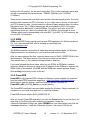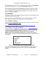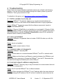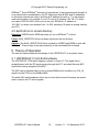
1
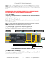
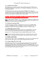
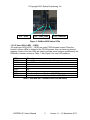
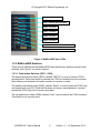
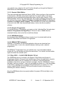
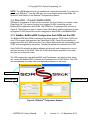
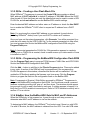
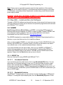
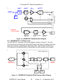
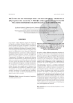
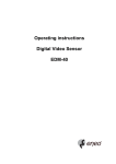
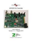
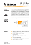
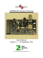
UDPSDR-HF1 Receiver Front-end User’s Manual Version 1.1 – 16 September 2013 © Copyright 2013 Zephyr Engineering, Inc © Copyright 2013 Zephyr Engineering, Inc 1 HARDWARE DESCRIPTION 1 1.1 UDPSDR-HF1 CONNECTORS 1.1.1 UDPSDR-HF1 CONNECTORS 1.2 BEMICROSDK CONNECTORS, SWITCHES AND LEDS 1.2.1 BEMICROSDK CONNECTORS 1.2.2 BEMICROSDK LEDS 1.2.3 BEMICROSDK SWITCHES 1 1 3 3 4 6 2 QUICK START GUIDE 8 3 DETAILED OPERATION 8 3.1 3.1.1 3.1.2 3.2 3.3 3.3.1 3.3.2 3.3.3 3.3.4 3.4 3.4.1 3.4.2 3.4.3 3.5 3.5.1 3.5.2 3.5.3 3.5.4 4 4.1 4.2 4.3 4.4 4.5 5 5.1 5.2 6 STEP QS1 – DOWNLOAD AND INSTALL PROGRAMMING SOFTWARE HOW TO DETERMINE WHAT PROGRAMMING SOFTWARE YOU NEED DOWNLOAD AND INSTALL SOFTWARE STEP QS2 – INSTALL USB BLASTER DRIVER STEP QS3 – PROGRAM BEMICROSDK SIDEBAR: BEMICROSDK CONFIGURATION FLASH ROM AND THE UFB QS3A – CREATING A USER FLASH BLOCK FILE QS3B – PROGRAMMING THE BEMICROSDK CONFIGURATION FLASH ROM SIDEBAR: HOW THE BEMICROSDK GETS ITS MAC AND IP ADDRESSES STEP QS4 – MAKE EXTERNAL CONNECTIONS QS4B – ANTENNA QS4C – ETHERNET DATA CONNECTION QS4D – POWER STEP QS5 – INSTALL AND RUN GUI SOFTWARE HDSDR SDR# POWERSDR GNURADIO TROUBLESHOOTING 18 PATH VARIABLE INCORRECTLY SET JAVA NOT INSTALLED NETWORK CABLE NOT PLUGGED IN INCORRECT NETWORK ADDRESS ASSIGNMENTS EXTIO.DLL NOT IN CORRECT DIRECTORY 18 18 18 18 19 THEORY OF OPERATION 19 UDPSDR-HF1 FRONT-END HARDWARE UPDSDR-HF1 FPGA CODE 19 20 SPECIFICATIONS UDPSDR-HF1 User’s Manual 9 9 10 11 12 12 13 13 13 14 14 14 14 15 15 16 16 17 21 i Version 1.1 – 16 September 2013 © Copyright 2013 Zephyr Engineering, Inc 1 Hardware Description The following sections will help familiarize you with the setup and connections to your SDRstickTM HF1 SDR receiver. 1.1 UDPSDR-HF1 Connectors See Figure 1 for UDPSDR-HF1 connector locations. J3- OPT Power In J2- OPT Power In J5- Phones Out J4- RF Input J1 - BeMicro SDK Figure 1 UDPSDR-HF1 Connectors 1.1.1 UDPSDR-HF1 Connectors 1.1.1.1 J1 – BeMicroSDK connector The J1 80-pin dual-sided MEC-style edge connector plugs onto the gold-finger edge connector on the end of the BeMicroSDK. J1 connects digital data and power between the HF1 and the BeMicroSDK. Note that the HF1 uses the BeMicroSDK pin assignments, not the MEC connector pin assignments from the Samtec data sheet. Pin 1 is marked on HF1 by a white dot. The pin 1 end of J1 is closest to capacitor C1. The BeMicroSDK pin 1 is clearly marked with a “1”. The correct HF1-to-BeMicroSDK pairing is shown in Figure 2. UDPSDR-HF1 User’s Manual 1 Version 1.1 – 16 September 2013 © Copyright 2013 Zephyr Engineering, Inc BeMicroSDK Pin 1 J1 Pin 1 Figure 2 - The correct HF1-BeMicroSDK pairing 1.1.1.2 J3 and J2 - Power In Power is supplied to the receiver in one of three ways (listed in most-to-least desirable order): USB, J3 or J2. The combination SDRstickTM HF1 requires 5VDC at about 400mA. J3 and J2 are equivalent, since they are in parallel. J3 mates with a 2.35mm x .0.7mm barrel plug (CUI part #PP-012, Digi-Key part#CP-012-ND). J2 is provided for either a two-pin SMT header (TE part #3-647166-2, Digi-Key part #A113590-ND) or just pads for soldering wire leads. The center pin of J3 is positive. J2 pin 1 is positive and is marked with a white dot adjacent to the pad. See Figure 3 for details. USB 2.0 or USB 3.0 ports can power the SDRstickTM HF1. Center Pin +5VDC@400mA 2.35mm x 0.70mm GND - Pin 2 +5VDC - Pin 1 Figure 3 - Power Connector Detail UDPSDR-HF1 User’s Manual 2 Version 1.1 – 16 September 2013 © Copyright 2013 Zephyr Engineering, Inc NOTE: In order to use the USB port for power, the Altera USB Blaster driver must be loaded onto the PC. The BeMicroSDK will not even turn on until this driver is properly installed. No driver is required to power the receiver from J3 or J2. See the Quick Start Guide. WARNING: NEVER APPLY EXTERNAL POWER TO J3 or J2 WHILE PLUGGED INTO ANY USB PORT! THIS CAN DAMAGE YOUR USB PORT! 1.1.1.3 J4 – RF Input The receiver RF input is connected to J4, a standard SMA jack. J4 may be connected directly to a 50-ohm antenna. 1.1.1.4 J5 – Phones Out (optional) Plug headphones into J5, a 3.5mm stereo jack, which connects to the on-board audio DAC/headphone amplifier. Note: The current FPGA code implementations send receive audio to the PC sound system rather than to J5. It is available as an option for the user. 1.2 BeMicroSDK Connectors, Switches and LEDs See Figure 4 for BeMicroSDK connector, switch and LED locations. X201 - USB S502-S504 – User Buttons X602 - Ethernet LED1-8 – User LEDs Pin 1 V701, V703, V704 – Status LEDs SW1 – User Switches X701 – MEC Connector Figure 4 - BeMicroSDK Connectors, Switches and LEDs 1.2.1 BeMicroSDK Connectors There are three connectors on the BeMicroSDK: one USB type A, one Ethernet RJ-45 and one 80-contact MEC edge connector. UDPSDR-HF1 User’s Manual 3 Version 1.1 – 16 September 2013 © Copyright 2013 Zephyr Engineering, Inc 1.2.1.1 USB Connector (X201) The USB connector is used to program both the FPGA configuration RAM and the BeMicroSDK configuration flash memory. The BeMicroSDK appears to the host PC as an Altera Byte Blaster. The USB connector can also be used to power the SDRstickTM HF1 when it is connected to a port that can supply sufficient power. USB 2.0 ports, USB 3.0 ports and powered hubs can power this 400mA load. A 5V well regulated power supply on J3 (or J2) can be used instead of the BeMicroSDK USB connector. WARNING: NEVER APPLY EXTERNAL POWER TO J3/P1 WHILE PLUGGED INTO ANY USB PORT! THIS CAN DAMAGE YOUR USB PORT! Note: In order to get the SDRstickTM HF1 to power up from a Windows PC USB port, the Altera Byte Blaster driver must be installed. A Byte Blaster driver is not needed for PCs running Linux in order to power up the SDRstickTM HF1. 1.2.1.2 Ethernet Connector (X602) The Ethernet connector (X602) is a standard RJ-45 connector. The BeMicroSDK supports 10/100Mbps Ethernet, but 100Mbps is required for SDRstick TM HF1. This connection is used for the receive data stream to a host PC or network switch. 1.2.1.3 MEC Edge connector (X701) The 80-contact MEC-style edge connector plugs into the UDPSDR-HF1 front-end board. All of the digital signals between the HF1 and the BeMicroSDK use this connector. Pin 1 is clearly marked on both the BeMicroSDK and the HF1 board. Note: The pin numbering is different than that shown on the Samtec connector data sheet. Be sure to only plug the boards together in the orientation shown in Figure 2. 1.2.2 BeMicroSDK LEDs There are two groups of LEDs on the BeMicroSDK: a group of 3 status LEDs below the RJ-45 connector and a group of 8 user LEDs alongside the MEC connector. 1.2.2.1 Status LEDs (V701, V703, V704) The leftmost status LED (V701) is the green power indicator LED. The middle status LED (V703) is yellow, and is lit when the FPGA CONF_DONE pin goes high. The rightmost status LED (V704) is red and lights when pin 4 of the MEC connector is pulled low (PWREN2# asserted). Since HF1 never drives this pin low, this LED should never be lit. See Figure 5 for the status LED locations. UDPSDR-HF1 User’s Manual 4 Version 1.1 – 16 September 2013 © Copyright 2013 Zephyr Engineering, Inc V701 – Power V703 – CONF_DONE V704 – PWREN2# Figure 5 - BeMicroSDK Status LEDs 1.2.2.2 User LEDs (LED1 – LED8) The eight user LEDs (LED1 – LED8) are under FPGA firmware control. Since the function of these LEDs is defined by the FPGA firmware, they can have any desired meaning. Some of the user LEDs are used to indicate some common conditions by the SDRstickTM firmware, shown in Table 1. See Figure 6 for user LED locations. LED LED8 (top) LED7 LED6 LED5 LED4 LED3 LED2 LED1 (bottom) Function lit on A/D converter overload condition lit on FIFO overflow (internal error condition) off off off off Heartbeat: flashes ~ 1Hz from HF1 80MHz clock Heartbeat: flashes ~ 1Hz from BeMicroSDK 50MHz clock Table 1- UDPSDR-HF1 Firmware User LED Indicators UDPSDR-HF1 User’s Manual 5 Version 1.1 – 16 September 2013 © Copyright 2013 Zephyr Engineering, Inc LED8 – ADC Overload LED7 – Internal FIFO Overflow LED6 – not used LED5 – not used LED4 – not used LED3 – not used LED2 – UDPSDR-HF1 Clock Heartbeat LED1 – BeMicroSDK Clock Heartbeat Figure 6- BeMicroSDK User LEDs 1.2.3 BeMicroSDK Switches There are five switches on the BeMicroSDK: three push-button switches and two slide switches. See Figure 7 for switch locations. 1.2.3.1 Push-button Switches (S502 – S504) The bottom push-button switch (S502), labeled “RECFG”, is used to force an FPGA reconfiguration. When this switch is pressed, the FPGA is reloaded from the on-board flash memory and restarts in the same manner as a power-on reset. The middle push-button switch (S503), labeled “Reset”, is used to reset the FPGA logic and internal soft-core CPU. Note that this does not cause a reconfiguration; it merely restarts the FPGA logic from a known reset state. The top push-button switch (S504), labeled “User”, can be read by the FPGA firmware. This switch is not currently used. UDPSDR-HF1 User’s Manual 6 Version 1.1 – 16 September 2013 © Copyright 2013 Zephyr Engineering, Inc S504 – not used S503 – FPGA Reset S502 - Reconfiguration SW1-2 not used SW1-1 not used Figure 7 - BeMicroSDK Switches 1.2.3.2 Slide Switches (SW1-1, SW1-2) The two slide switches, SW1-1 (bottom) and SW1-2 (top), can be read under FPGA firmware control. SW1-1 and SW1-2 are not currently used by the FPGA firmware. UDPSDR-HF1 User’s Manual 7 Version 1.1 – 16 September 2013 © Copyright 2013 Zephyr Engineering, Inc 2 Quick Start Guide This quick start guide will lead you through the steps to get your SDRstickTM HF1 receiver operating. Please refer to Section 3 for in-depth information on each of these steps. If your BeMicroSDK came pre-programmed from the factory, you can skip steps QS1 and QS3. QS1. Download and install programming software a. Download and install Altera Quartus II Web Edition b. Download and install SDRstickTM Programmer QS2. Install Altera USB Blaster hardware driver (only needed for Windows) a. Plug in BeMicroSDK and point to driver b. Verify that power LED V701 lights on BeMicroSDK QS3. Program BeMicroSDK a. Use SDRstickTM Programmer to create User Flash Block FLASH file (make sure to choose an IP address on the same subnet as the PC, or use DHCP with a server that issues IP addresses on the same subnet) b. Use SDRstickTM Programmer to program three FLASH files (two firmware and one user block) into BeMicroSDK flash memory QS4. Make external connections a. Remove BeMicroSDK from computer b. Install HF1 onto BeMicroSDK and connect antenna to J4 c. Connect Ethernet cable to host PC or network d. Connect power and observe two flashing heartbeat LEDs on BeMicroSDK QS5. Install and Run GUI software on computer a. One or more of GNURadio, HDSDR, SDR#, PowerSDRTM are options b. ExtIO_SDRSTICK.dll must be placed into the same directory as the executable files – a separate copy is required for each GUI c. For HDSDR and SDR#, observe that SDRstick discovery was successful d. For PowerSDRTM, configure for Hermes, 1 RX and 384K data rate e. Receive audio is delivered via the PCs sound system 3 Detailed Operation The sections of this chapter contain (or provide links to) detailed information on each step necessary to successfully set up the SDRstickTM HF1 Software Defined Receiver. It is beyond the scope of this document to cover operating-system specific procedures that are necessary to set up the receiver. It is assumed that the user is capable of performing the tasks in the following list. Please consult your PC and/or operating system documentation or use on-line searches to become comfortable with these procedures. UDPSDR-HF1 User’s Manual 8 Version 1.1 – 16 September 2013 © Copyright 2013 Zephyr Engineering, Inc Install applications Check system information and update hardware drivers Enable/disable both wired and wireless network ports Change PC IP address and network mask Enable and disable PC DHCP client Use console to check IP address and ping network devices Check/set environment variables using the system properties dialog box Navigate PC file system to copy and move files 3.1 Step QS1 – Download and Install Programming Software The design and programming software for the BeMicroSDK is available for free download from the Internet. (Note that this software is different from the SDR GUI software that is used to operate the radio. We will cover that in section 3.5) There are four components to this support software. Which of the four components you need are determined by how you are going to use your HF1 receiver. See Table 2 for a quick summary of the support software components. Support Software Size Source Used To Quartus II Web Edition Design Software 4.4GB Altera.com Write, modify, compile and program FPGA firmware into FPGA configuration SRAM Quartus II Programmer 140MB Altera.com Program FPGA firmware into FPGA configuration SRAM Included in Quartus II Web Edition and Quartus II Programmer Enable BeMicroSDK USB power (Windows); required to program FPGA configuration SRAM or BeMicroSDK configuration flash memory svn.SDRstick.com Program BeMicroSDK configuration flash memory; create SDRstickTM User Block FLASH files USB Blaster Driver TM SDRstick Programmer - 750KB Table 2- Support Software Components 3.1.1 How to Determine What Programming Software You Need To help you to determine what software to load, first we will explain a bit about how the FPGA works and then show you what each software program does. 3.1.1.1 SideBar: FPGA Configuration Technical Details The FPGA stores its configuration (firmware) in internal static memory cells (SRAM). This internal FPGA memory is aptly called configuration SRAM. Since configuration SRAM is volatile, it must be initialized every time the FPGA is powered on. This can be done in two ways: from the USB port or from the BeMicroSDK on-board flashprogrammable ROM. When power is first applied, dedicated circuitry inside the FPGA automatically loads the configuration SRAM from this configuration flash ROM, if it contains FPGA firmware. (Note that even if the ROM does contain a valid firmware load, UDPSDR-HF1 User’s Manual 9 Version 1.1 – 16 September 2013 © Copyright 2013 Zephyr Engineering, Inc the FPGA configuration SRAM can be overwritten with a new firmware load from the USB port at any time.) For the SDRstickTM HF1 receiver to work immediately on power-up, the BeMicroSDK configuration flash ROM must be programmed with the FPGA firmware load. The Quartus II Web Edition software and the Quartus II Programmer software are both capable of writing directly to the FPGA configuration SRAM, but not to the BeMicroSDK configuration flash ROM. The SDRstickTM Programmer software was developed to write FPGA firmware loads to the BeMicroSDK configuration flash ROM, allowing the receiver to run immediately after power is applied. The SDRstickTM Programmer uses components from the Quartus II Web Edition, as well as the USB Blaster Driver. Therefore, the USB Blaster Driver and the Quartus II Web Edition software must be installed in order to use SDRstickTM Programmer. 3.1.1.2 Determine Software Components See table Table 3 to determine what software you will need to install, depending on how you want to configure your SDRstickTM HF1 receiver. If your BeMicroSDK came pre-loaded from the factory and you are powering it from external power, you do not need to install any support software. If, at some point, you want to upgrade the firmware, you will need to install the necessary components from Table 3. You can do this at any time, as you need them. To Do This You Need This Support Software Power HF1 from external power none Power HF1 from USB power (Linux) none Power HF1 from USB power (Windows) USB Blaster Driver Program or update FPGA firmware into BeMicroSDK configuration flash memory Quartus II Web Edition, USB Blaster Driver, SDRstickTM Programmer Program FPGA firmware into FPGA configuration SRAM for debugging (this is not common) Quartus II Web Edition or Quartus II Programmer, USB Blaster Driver Write custom FPGA firmware and program into FPGA configuration SRAM Quartus II Web Edition, USB Blaster Driver Write custom FPGA firmware and program into BeMicroSDK configuration flash memory Quartus II Web Edition, USB Blaster Driver, SDRstickTM Programmer Table 3 - Support Software Requirements 3.1.2 Download and Install Software After you have determined what support software you need, go to <altera.com> and/or <svn.sdrstick.com> and download the installation files. If you need more detailed installation information, please download the beradio lab from the <beradio> section of UDPSDR-HF1 User’s Manual 10 Version 1.1 – 16 September 2013 © Copyright 2013 Zephyr Engineering, Inc <svn.sdrstick.com>. Sections 2.4 and 2.5 of the lab walk you through the Quartus II Web Edition and USB Blaster driver installation. 3.1.2.1 Quartus II Web Edition This is an extremely large download (about 4.4GB). Unless you have a fast connection to the Internet, it will take a long time to download. You may be able to save some download time by downloading individual files rather that the entire Quartus II Web Edition package. Click on the “Individual Files” tab to select individual components. You will need two components: Quartus II Software (includes Nios II EDS and Cyclone II, Cyclone III, Cyclone IV device support). The combined size of these two components is only a bit over 2GB. After the download finishes, click on the file to install the software. 3.1.2.2 Quartus II Programmer To load the Quartus II Programmer, you must go to the “Individual Files” tab and select Quartus II Programmer and SignalTap II. The size is about 140MB. After the download finishes, click on the file to install the software. 3.1.2.3 USB Blaster Driver No download of the USB Blaster driver is required, as it is included with both the Quartus II Web Edition and Quartus II Programmer. 3.1.2.4 SDRstickTM Programmer SDRstickTM Programmer is a Windows application that you can download from <svn.sdrstick.com>. Look in the <sdrstick-release> directory under <sdrstickprogrammer>. The SDRstickTM Programmer from <svn.sdrstick.com> is an executable windows installer file. Run the installer and follow the instructions. To un-install, run the installer again and select the uninstall option. 3.2 Step QS2 – Install USB Blaster Driver The USB Blaster driver is included in the Quartus II Web Edition and Quartus II Programmer software. Once you have installed one of those two applications, plug the BeMicroSDK (without the HF1 attached) into a USB port. Cancel the windows installation of the driver, and go to the device manager. Find the “USB Blaster” entry in the table (it will have a yellow “!” next to it) and update the driver for it. Point the updater to the drivers, typically in the <C:\altera\13.0\quartus\drivers> for version 13.0. The system variable QUARTUS_ROOTDIR should contain the path to the directory containing the <drivers> directory. Once the USB Blaster driver is properly installed, the power LED should light on the BeMicroSDK. UDPSDR-HF1 User’s Manual 11 Version 1.1 – 16 September 2013 © Copyright 2013 Zephyr Engineering, Inc NOTE: The USB Blaster driver is not available as a separate download. If you intend to power your SDRstickTM from the USB port, you must download and install either the Quartus II Web Edition or the Quartus II Programmer software. 3.3 Step QS3 – Program BeMicroSDK SDRstickTM Programmer is used for two functions. The first function is to create a User Flash Block file. The second function is to program FLASH format files into the BeMicroSDK configuration flash ROM. The SDRstickTM Programmer GUI is shown in Figure 8. The left pane is used to create a User Flash Block, and the right pane is used to program FLASH format files into the configuration flash ROM on the BeMicroSDK. 3.3.1 SideBar: BeMicroSDK Configuration flash ROM and the UFB The BeMicroSDK flash ROM is divided up into three sections: FPGA fabric, NIOS softcore CPU program code and the User Flash Block (UFB). Each of these sections is programmed from a FLASH format file. Two of these files provide the functionality of the FPGA and are supplied by the factory. The third file defines the contents of the UFB. Each FLASH file contains a starting address and a length, and corresponds to one of the three sections of the ROM. Thus, the FLASH files may be specified in any order, and one, two or three at a time. The UFB contains the user-defined MAC and IP addresses, and a flag bit that, when set, causes the BeMicroSDK to request an IP address from a DHCP server. The UFB can be expanded to include other user-defined parameters in the future. Software Revision Create UFB Pane Program Flash Pane Figure 8- SDRstickTM Programmer Window UDPSDR-HF1 User’s Manual 12 Version 1.1 – 16 September 2013 © Copyright 2013 Zephyr Engineering, Inc 3.3.2 QS3a – Creating a User Flash Block File When SDRstickTM Programmer is opened, the Create UFB pane contains a default MAC address of 00:07:ed:fc:fd:fe, a default IP address of 192.168.1.26 and the DHCP client turned off. Note that these are only the defaults that may be used to create a UFB FLASH file, and do not reflect the current BeMicroSDK network settings. Enter the desired MAC address and either enter an IP address or check the Use DHCP box to enable the SDRstickTM DHCP client to request an IP address from a DHCP server. Note: You must specify a unique MAC address on your network for each device (including SDRstickTM radios) even if you use DHCP to obtain an IP address. Once you have set the network parameters, click Generate. You will be prompted for a path and a file name for the UFB FLASH file. For the network parameters to take effect, you must program this file into the BeMicroSDK configuration flash ROM using the Program Flash pane. Note: A Java script generates the FLASH file. If file generation appears to complete normally but no FLASH file is created, check to make sure an up to date version of Java is installed on the PC. 3.3.3 QS3b – Programming the BeMicroSDK Configuration Flash ROM Use the Program Flash pane to program FPGA firmware FLASH files and UFB FLASH file into the BeMicroSDK configuration flash ROM. Click the Add… button to add files to the Files to Program window. Files can be added in any order. A section of the ROM will only be programmed if the corresponding FLASH file appears in this window, otherwise that section will be unaffected. You can update the UFB without updating the firmware, and vice-versa. Click the Program button to program the files into the configuration flash on the BeMicroSDK. Note: Components of Quartus II Web Edition are used by SDRstickTM Programmer to program the BeMicroSDK configuration flash ROM. You should see several command windows containing scrolling text “pop up” and then close. The windows should appear long enough for you to read a few lines on each one. If nothing appears to happen, it is likely that your PATH variable is incorrectly set. Refer to PATH variable incorrectly set in section 4.1 for a solution. 3.3.4 SideBar: How the BeMicroSDK Gets Its MAC and IP Addresses When the SDRstickTM is first powered on, it goes through a multi-step process to determine what MAC and IP address to use on the network. To determine its MAC address, the SDRstickTM first looks to see if there is a valid UFB. If a valid UFB exists, the MAC address is obtained from the UFB. If no valid UFB exists UDPSDR-HF1 User’s Manual 13 Version 1.1 – 16 September 2013 © Copyright 2013 Zephyr Engineering, Inc (I.e., it was not programmed into the configuration flash ROM), then the MAC address is set to 00:07:ed:01:23:45. This is in the Altera block of IP addresses with the last three octets set to 0x012345. Note: In order to use multiple SDRstickTM radios on the same network, you MUST set unique MAC addresses for each radio that are different from any other MAC address on the same network. To determine its IP address, the SDRstickTM first looks to see if there is a valid UFB. If there is a valid UFB, the SDRstickTM then looks to see if the DHCP client is enabled. If it is, then a DHCP request is broadcast. If an IP address is received from the DHCP server, that IP address is used. If the DHCP request is unsuccessful (for example, a timeout occurs) or the DHCP client is not enabled, the SDRstickTM uses the IP address from the UFB instead. If there is no valid UFB, the SDRstickTM broadcasts a DHCP request. If an IP address is received from the DHCP server, that IP address is used. If the DHCP request is unsuccessful (for example, a timeout occurs), the SDRstickTM uses the default IP address of 192.168.1.25. 3.4 Step QS4 – Make External Connections The SDRstickTM requires three external connections to function: antenna, Ethernet data connection and power input. 3.4.1 QS4b – Antenna Connect an antenna to the J4 SMA connector. Note that there is no bandpass filtering at the receiver front-end. Excessive voltage at the antenna jack can damage the receiver. Any voltage above about 3V p-p may damage the input circuitry. 3.4.2 QS4c – Ethernet Data Connection Connect the BeMicroSDK Ethernet port either directly to a PC network port or to a LAN through a 100Mbps switch. Even though the port hardware supports 10Mbps and 100Mbps, a 100Mbps connection is required for proper operation. (Even at the lowest sample rate, 10Mbps Ethernet has insufficient bandwidth to support this receiver.) 3.4.3 QS4d – Power Either plug the BeMicroSDK into a USB 2.0 or USB 3.0 port or connect a power supply to J3. The BeMicroSDK and UDPSDR-HF1 combination requires about 400mA at 5VDC to operate properly. While the best way to supply power is through connector J3, you may also supply power through the USB connector. Since the BeMicroSDK negotiates for power over the USB port before it turns on, you cannot use a USB charger to power SDRstickTM HF1 regardless of its current capacity. UDPSDR-HF1 User’s Manual 14 Version 1.1 – 16 September 2013 © Copyright 2013 Zephyr Engineering, Inc Note: Clean power is especially important given the high sensitivity of this receiver. USB power is not noted for its purity. If you experience excessive receiver noise while on USB power, especially at lower frequencies, consider using a well-filtered external power supply instead. WARNING: NEVER APPLY EXTERNAL POWER TO J3/P1 WHILE PLUGGED INTO ANY USB PORT! THIS CAN DAMAGE YOUR USB PORT! 3.5 Step QS5 – Install and Run GUI Software Tutorials on SDR GUI software are beyond the scope of this manual, but here are some quick links and tips for setting up four common but powerful programs that will work with your SDRstickTM HF1 receiver. 3.5.1 HDSDR High Definition Software Defined Radio, or HDSDR, is a freeware SDR program for Windows 2000 through Windows 8. HDSDR is written by Mario Taeubel, DG0JBJ, and is an advanced version of Winrad. This is an excellent SDR GUI, and may be downloaded from the HDSDR web site < http://www.hdsdr.de/> The HDSDR download is an executable installer for Windows. Simply download it to a directory on your local drive and run it to install the software. After you have installed HDSDR, you must place a copy of ExtIO_SDRSTICK.dll in the directory that HDSDR runs. The latest version of this file can be found on the web at <svn.sdrstick.com> in the <sdrstick-release/software> directory. If you have followed all of the above steps, when you run HDSDR, an SDRstick TM network discovery dialog box will pop up showing the IP address of the SDRstick TM receiver that HDSDR found on the network. Click OK, and the HDSDR main screen appears. Simply click the Start button and you are on the air! 3.5.1.1 HDSDR Tips Here are a few tips for using HDSDR with SDRstickTM HF1. 3.5.1.1.1 Soundcard Selection If you are having receiver audio issues, click on the Soundcard [F5] button. You can then select one of several options, in case your PC has more than one audio output device. Also note that there is a Mute button in the left center of the cluster of blue buttons above the date display. HDSDR saves the setting of Mute from run to run, so if you had the receiver muted when you shut HDSDR down, it will still be muted when you launch HDSDR again. 3.5.1.1.2 Bandwidth Selection The SDRstickTM firmware gives you two options for input sampling rate: 1.25Msps and 384Ksps. To change the input sampling rate, click the Bandwidth [F6] button. At the UDPSDR-HF1 User’s Manual 15 Version 1.1 – 16 September 2013 © Copyright 2013 Zephyr Engineering, Inc bottom of the left column, you will see a dialog box. Click on the small down-arrow and you will be presented with two selections, “384000” (384Ksps) and “1250000” (1.25Msps). There are two reasons that you might want to select the lower sampling rate. The lower sampling rate requires less CPU resources, so you might want to choose a lower rate if you PC is slower or older. Another reason to choose a lower sampling rate is to reduce the network load. The 1.25Msps sample rate will consume about 50% of the entire 100Mbps network bandwidth, or about 50Mbps. This will not work over most WiFi connections unless you reduce the sample rate. At 384Ksps, the data rate is about 15Mbps, which may be transportable over most 802.11g or 802.11n WiFi networks, but not over 802.11b networks. 3.5.2 SDR# SDR# (read SDR Sharp) is a high performance SDR application for Windows written in C#. It is a fully featured SDR, and is available for download here: <http://sdrsharp.com/> The SDR# download is a zip archive, rather than an executable installer for Windows. Simply download it to a directory on your local drive and unzip the files. After you have unzipped the files, you must place a copy of ExtIO_SDRSTICK.dll in the same directory. The latest version of this file can be found on the web at <svn.sdrstick.com> in the <sdrstick-release/software> directory. If you have followed the above steps, when you run SDR#, an SDRstick TM network discovery dialog box will pop up showing the IP address of the SDRstickTM receiver that SDR# found on the network. Click OK, and the SDR# main screen appears. Simply click the Play button and you are on the air! 3.5.3 PowerSDR PowerSDR is fully featured SDR software for Windows, and is available for download from the openHPSDR downloads page here: <http://openhpsdr.org/download.php>. Scroll down to near the bottom, under the Windows section, and look for PowerSDR_mRX_v3.1.5.0_Setup or a similar revision. The PowerSDR download is an executable installer for Windows. Simply download it to a directory on your local drive and run it to install the software. PowerSDR does not require ExtIO_SDRSTICK.dll. After you launch PowerSDR and before you click the Power button for the first time, you must click on the Setup tab and configure your hardware. Under the <General><Hardware Config> tab, select HERMES as your Radio Model, and click the 1-receiver check box. Under the <General><Options> tab, select HIGH as the UDPSDR-HF1 User’s Manual 16 Version 1.1 – 16 September 2013 © Copyright 2013 Zephyr Engineering, Inc Process Priority. Under the <Audio><Primary> tab, select 384000 in the Sample Rate box. Under the <Audio><VAC1> tab, click the Enable VAC 1 check box. Close the Setup window and click the Power button and you are on the air! If you go back to the Setup window now, under the <General><Hardware Config> tab, you will see your SDRstickTM IP and MAC addresses displayed in the lower right corner of the window, under Hermes Address. 3.5.4 GNURadio GNURadio is an open-source software development toolkit for Linux and Windows used to implement software-defined radios. These instructions are for GNURadio version 3.6.5.1 under Ubuntu Linux 12.04LTS. Other versions are available; the installation procedure may be different. 3.5.4.1 GNURadio Installation Point your browser to the GNURadio web page below and follow the instructions in the section Using the build-gnuradio script. http://gnuradio.org/redmine/projects/gnuradio/wiki/InstallingGR#Using-the-build-gnuradio-script 3.5.4.2 SDRstickTM Source Block Installation Point your browser to the SDRstickTM web SVN server here: <http://svn.sdrstick.com> and download the file gr-sdrstick-sourceblock.tar.gz from the <sdrstick-release/gnuradio/sourceblock> directory. Extract the files form this gzip archive into a directory of your choice. Follow the directions in the extracted Readme.txt file to install the GNURadio SDRstickTM sourceblock and an example GRC flowgraph. The contents of the Readme.txt file are reproduced in Figure 9 for your convenience. - Uncompress in directory of your choice. - cd gr-sdrstick - mkdir build - cd build - cmake ../ - make - sudo make install - sudo ldconfig Figure 9 - GNURadio Sourceblock Installation Readme.txt File Start gnuradio-companion and open the example flowgraph using <file><open>. The flowgraph is named sdrstick_am_rx.grc and is located in the gr-sdrstick/apps directory. UDPSDR-HF1 User’s Manual 17 Version 1.1 – 16 September 2013 © Copyright 2013 Zephyr Engineering, Inc 4 Troubleshooting Some of the more common problems and their solutions are outlined in the following sections. If you are still stuck after reading through this chapter, please log onto the SDRstickTM Yahoo group and ask for help. To subscribe to the group, go to http://groups.yahoo.com/groups/SDRstick 4.1 PATH variable incorrectly set Symptom: SDRstickTM Programmer appears to run, but the several windows just momentarily flash up on the screen and the BeMicroSDK does not get programmed. Cause: SDRstickTM Programmer cannot find the software components it needs to program the BeMicroSDK files. Solution: If Quartus II Web Edition is not installed, you must install it. If Quartus II Web Edition is already installed, you need to add a string to your PATH variable that points to the installed directory, typically C:\altera\13.0\quartus\bin, where 13.0 is replaced by whatever version number you have installed. 4.2 Java not installed Symptom: SDRstickTM Programmer does not create a FLASH file when you click the Generate button. Cause: Java is not installed. Solution: Install a current version of Java. 4.3 Network cable not plugged in Symptom: SDRstickTM discovery fails. Cause: Ethernet cable not connected between SDRstickTM and PC or network switch. Solution: Make sure that there is an Ethernet connection between the SDRstickTM and the PC. Verify the connection by Pinging the SDRstickTM from the PC. Remember that the data flows through the Ethernet port, not the USB port. 4.4 Incorrect network address assignments Symptom: SDRstickTM discovery may or may not succeed, but communication fails and the receiver is unresponsive. Cause: The PC and the SDRstickTM are on different subnets. Solution: Either reprogram the SDRstickTM to an IP address within the same subnet as the PC, or change the IP address of the PC so that it is within the same subnet as the UDPSDR-HF1 User’s Manual 18 Version 1.1 – 16 September 2013 © Copyright 2013 Zephyr Engineering, Inc SDRstickTM. Since SDRstickTM discovery is a broadcast, it may succeed even though it is on a subnet that is unreachable by the PC. Make sure that all MAC and IP addresses on the entire network are unique, and that all IP address bits with a “1” in the network mask are the same. For example, if your PC is set to IP address 192.169.1.10 with a net mask of 255.255.255.0, then you can set your SDRstickTM IP address to 192.168.1.xx, where xx=a number from 1 to 254, excluding 10 (which is already used by your PC). 4.5 ExtIO.dll not in correct directory Symptom: HDSDR and/or SDR# start right up, but no SDRstickTM is found. Cause: ExtIO_SDRSTICK.dll has not been copied into the run directory. Solution: The ExtIO_SDRSTICK.dll file is required for HDSDR and SDR# to work with SDRstickTM. Place a copy in the same directory as the executable file is located. 5 Theory of Operation The next two sections describe the design of the UDPSDR-HF1 in very basic terms. 5.1 UDPSDR-HF1 Front-End Hardware The UDPSDR-HF1 PCB block diagram is shown in Figure 10. The signal flow is straightforward, with the RF signal passing through the LPF, anti-alias filter and ADC driver before being sampled by the ADC. The ADC can be clocked either by the on-board 80MHz clock oscillator or a CLK_IN signal from the FPGA on the BeMicroSDK. The audio DAC and headphone driver are not used by the current firmware, as receive audio is sent to the PC sound system. UDPSDR-HF1 User’s Manual 19 Version 1.1 – 16 September 2013 © Copyright 2013 Zephyr Engineering, Inc EXTERN AL ANTENN A LOW-PASS FI LTER ANTI ALI AS FI LTER 30 MH z 30 MH z ADC D RI VER 14b@ 80MS PS ADC 14 ADC 20dB PW R BeMicro SDK (80 pins) 80MHz ESD PR OT C LK OU T SEL OSC UDPSDR- HF1 14 bits @ 80 M SPS 5kH z AUD IO D AC 14b@ 50KS PS SER IAL D AC PHONES C LK IN 0dB R ECONSTR UC TI ON FI LTER H EAD PHON E D RI VER Figure 10 - UDPSDR-HF1 Hardware Block Diagram 5.2 UPDSDR-HF1 FPGA Code The UDPSDR-HF1 simplified FPGA block diagram is shown in Figure 11. This very basic flow shows the Numerically Controlled Oscillator and the two multipliers that serve as a down-converter, followed by two decimating filters. The I/Q data is buffered by a FIFO and sent to the Ethernet MAC for transmission as UDP packets on the network. BeM icro EP4CE22 FPGA 30 16 0 I 14 ADC N CO Q 4 C IC LPF FI FO 10/ 100 MAC 10/ 100 PHY 50 90 UDPSDR- HF1 14 bits @ 80 M SPS 16 1.25 M Hz RF Bandw idth D EC FR EQ 30 N IOS I I 32Mx16 MDD R D RAM U SER FLASH B LOC K Figure 11 - UDPSDR-HF1 Simplified FPGA Firmware Block Diagram UDPSDR-HF1 User’s Manual 20 Version 1.1 – 16 September 2013 © Copyright 2013 Zephyr Engineering, Inc An internal NIOS soft-core CPU controls all of the processes and the data flow. The NIOS CPU also controls the boot loader functions and external flash memory programming operations, not shown. 6 Specifications Frequency Range: 100kHz to 30MHz, Digital Direct Sampling (DDS) Input impedance: 50 ohms RF input clipping level (typical): -7dBm Maximum Display Bandwidth: 1.25MHz Sampling Width and Rate: 14bits @ 80Msps MDS: -118dBm @ 14MHz (500Hz BW) for 3dB noise floor increase Antenna connection: standard SMA Power consumption: +5VDC @ 400mA (including BeMicroSDK) Dimensions, UDPSDR-HF1: 31mm x 65mm (1.2”W x 2.6”L) Dimensions, including BeMicroSDK: 33mm x 185mm (1.3”W x 7.3”L) UDPSDR-HF1 User’s Manual 21 Version 1.1 – 16 September 2013