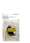
1
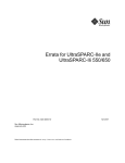
Leuze electronic
Area Scanning Distance Sensor
rotoScan ROD 4 / ROD 4-06 / ROD 4-08
Technical Description
Leuze electronic
Leuze electronic GmbH + Co KG
P.O. Box 11 11, D- 73277 Owen / Teck
Tel. +49(0)7021/ 573-0,
Fax +49(0)7021/ 573-199
E-mail: [email protected], www.leuze.de
Sales and Service
Sales Region East
Phone 035027/629-106
Fax 035027/629-107
Sales Region North
Phone 07021/573-306
Fax 07021/9850950
Postal code areas
20000-38999
40000-53999
56000-65999
97000-97999
Hamburg
Berlin
Hannover
Postal code areas
01000-19999
39000-39999
98000-99999
Düsseldorf
Dresden
Frankfurt
Nürnberg
Stuttgart
Owen/Teck
München
Sales Region South
Phone 07021/573-307
Fax 07021/9850911
Postal code areas
54000-55999
66000-96999
Worldwide
JP (Japan)
C. Illies & Co., Ltd.
Tel. Int. + 81 (0) 3 /34434111
Fax Int. + 81 (0) 3 /34434118
AT (Austria)
Ing. Franz Schmachtl KG
Tel. Int. + 43 (0) 732/76 46 -0
Fax Int. + 43 (0) 732/785036
FI (Finland)
SKS-automaatio Oy
Tel. Int. + 358 (0) 9/85 26 61
Fax Int. + 358 (0) 9/852 68 20
KR (South Korea)
Leuze electronic Co., Ltd.
Tel. Int. + 82 (0) 31/382 82 28
Fax Int. + 82 (0) 31/382 85 22
AU + NZ (Australia + New Zealand)
Balluff-Leuze Pty. Ltd.
Tel. Int. + 61 (0) 3 /97 64 23 66
Fax Int. + 61 (0) 3 /97 53 32 62
FR (France)
Leuze electronic sarl.
Tel. Int. + 33 (0) 1/60051220
Fax Int. + 33 (0) 1/60050365
MX (Mexico)
Leuze Lumiflex México, S.A. de C.V.
Tel. Int. + 52 (0) 81/83 71 86 16
Fax Int. + 52 (0) 81/83 71 85 88
BE (Belgium)
Leuze electronic nv /sa
Tel. Int. + 32 (0) 2/2531600
Fax Int. + 32 (0) 2/2531536
GB (United Kingdom)
Leuze Mayser electronic Ltd.
Tel. Int. + 44 (0) 1480/408500
Fax Int. + 44 (0) 1480/403808
MY (Malaysia)
Ingermark (M) SDN.BHD
Tel. Int. + 60 (0) 3 /60 34 27 88
Fax Int. + 60 (0) 3 /60 34 21 88
BR (Brasil)
Leuze electronic Ltda.
Tel. Int. + 55 (0) 11/ 4195 -6134
Fax Int. + 55 (0) 11/ 4195 -6177
GR (Greece)
UTECO A.B.E.E.
Tel. Int. + 30 (0) 210/ 4 2100 50
Fax Int. + 30 (0) 210/ 4 2120 33
NL (Netherlands)
Leuze electronic B.V.
Tel. Int. + 31 (0) 418 /65 35 44
Fax Int. + 31 (0) 418 /6538 08
CH (Switzerland)
Leuze electronic AG
Tel. Int. + 41 (0) 1/8340204
Fax Int. + 41 (0) 1/8332626
HK (Hong Kong)
Sensortech Company
Tel. Int. + 852/26 51 01 88
Fax Int. + 852/26 51 03 88
NO (Norway)
Elteco A /S
Tel. Int. + 47 (0) 35 /573800
Fax Int. + 47 (0) 35 /573849
CL (Chile)
Imp. Tec. Vignola S.A.I.C.
Tel. Int. + 56 (0) 32/351111
Fax Int. + 56 (0) 32/351128
HU (Hungary)
Kvalix Automatika Kft.
Tel. Int. + 36 (0) 1/2 7222 42
Fax Int. + 36 (0) 1/2 72 2244
PL (Poland)
Balluff Sp. z. o. o.
Tel. Int. + 48 (0) 22/833 15 64
Fax Int. + 48 (0) 22/833 09 69
CN (China)
Leuze electronic GmbH + Co KG
Shanghai Representative Office
Tel. Int. + 86(0)21/ 6888 0920
Fax Int. + 86(0)21/ 6888 0919
IL (Israel)
Galoz electronics Ltd.
Tel. Int. + 972 (0) 3/9023456
Fax Int. + 972 (0) 3/9021990
PT (Portugal)
LA2P, Lda.
Tel. Int. + 351 (0) 21/444 70 70
Fax Int. + 351 (0) 21/4 44 70 75
IN (India)
Global Tech (India) Pvt. Ltd.
Tel. Int. + 91 (0) 20 /24 4700 85
Fax Int. + 91 (0) 20 /24 47 0086
RO (Romania)
O`Boyle s.r.l.
Tel. Int. + 40 (0) 56 /20 13 46
Fax Int. + 40 (0) 56 /2210 36
IR (Iran)
Tavan Ressan Co. Ltd.
Tel. Int. + 98 (0) 21/2606766
Fax Int. + 98 (0) 21/2002883
RU (Russian Federation)
All Impex
Tel. + Fax +7 095/ 9332097
CO (Colombia)
Componentes Electronicas Ltda.
Tel. Int. + 57 (0) 4/35110 49
Fax Int. + 57 (0) 4/3511019
CZ (Czech Republic)
Schmachtl CZ s.r.o.
Tel. Int. + 420 (0) 2 /44 00 1500
Fax Int. + 420 (0) 2 /44 91 0700
DK (Denmark)
Desim Elektronik APS
Tel. Int. + 45/ 70220066
Fax Int. + 45/ 70222220
IT (Italy)
IVO Leuze Vogtle Malanca s.r.l.
Tel. Int. + 39 02 /2611 0643
Fax Int. + 39 02 /261106 40
SG + PH + ID (Singapore +
Philippines + Indonesia)
Balluff Asia Pte. Ltd.
Tel. Int. + 65 /62 52 43 84
Fax Int. + 65 /62 52 90 60
SI (Slovenia)
Tipteh d.o.o.
Tel. Int. + 386 (0) 1/ 2 00 5150
Fax Int. + 386 (0) 1/ 2 00 5151
SK (Slovakia)
Schmachtl SK s.r.o.
Tel. Int. + 421 (0) 2/ 58 27 56 00
Fax Int. + 421 (0) 2/ 58 27 56 01
TH (Thailand)
Industrial Electrical Co. Ltd.
Tel. Int. + 66 (0) 2/6 42- 67 00
Fax Int. + 66 (0) 2/6 42-42 49
TR (Turkey)
MEGA Teknik elek. San. ve Tic. Ltd.
Tel. Int. + 90 (0) 212/3 20 04 11
Fax Int. + 90 (0) 212/3 20 04 16
TW (Taiwan)
Great Cofue Technology Co., Ltd.
Tel. Int. + 886 (0) 2/29 83 80 77
Fax Int. + 886 (0) 2/29 85 33 73
US + CA (United States +
Canada)
Leuze Lumiflex Inc.
Tel. Int. + 1 (0) 973/ 5860100
Fax Int. + 1 (0) 973/ 586 15 90
ZA (South Africa)
Countapulse Controls (PTY.) Ltd.
Tel. Int. + 27 (0) 11/6157556
Fax Int. + 27 (0) 11/6157513
SE (Sweden)
Leuze SensorGruppen AB
Tel. + 46 (0) 8 /731 51 90
Fax + 46 (0) 8 /731 51 05
© All rights reserved, especially the right of reproduction, distribution and translation. Copying or
reproductions in any form require the written consent of the manufacturer.
Changes reflecting technical improvements may be made.
Part. No. 500 36 604
ES (Spain)
Leuze electronic S.A.
Tel. Int. + 34 93/4 09 79 00
Fax Int. + 34 93/490 58 20
D/GB 152/02 – 08/05
AR (Argentina)
Nortécnica S. R. L.
Tel. Int. + 54 (0) 11 /4757 -31 29
Fax Int. + 54 (0) 11 /4757 -1088
Leuze electronic
1
Table of contents
General information ........................................................................................................... 4
1.1
Explanation of symbols ........................................................................................................ 4
1.2
Declaration of conformity ..................................................................................................... 4
2
Safety Notices .................................................................................................................... 5
2.1
Safety standards .................................................................................................................. 5
2.2
Intended Use........................................................................................................................ 6
2.3
Working Safely ..................................................................................................................... 7
3
Description ......................................................................................................................... 9
3.1
Technical Overview.............................................................................................................. 9
3.2
3.3
Operating principle ............................................................................................................. 10
Application examples ......................................................................................................... 11
4
Mounting ........................................................................................................................... 13
4.1
4.2
Mounting location ............................................................................................................... 13
Mounting dimensions ......................................................................................................... 14
5
Electrical Connection ...................................................................................................... 15
5.1
Connecting the rotoScan ROD 4… .................................................................................... 15
5.1.1
5.1.2
5.1.3
5.1.4
Interface assignment X1 and X2.................................................................................................. 16
Connector assignments for interface X1...................................................................................... 16
Connector assignments for interface X2 (RS 232) ...................................................................... 17
Connector assignments for interface X2 (RS 422) ...................................................................... 18
5.2
Function characteristics of the X1 interface ....................................................................... 19
5.2.1
5.2.2
Input switching ............................................................................................................................. 19
Output switching .......................................................................................................................... 21
5.3
Function characteristics of the X2 interface ....................................................................... 22
5.3.1
Wiring the plug............................................................................................................................. 22
5.4
Integration in the control system ........................................................................................ 23
5.4.1
5.4.2
Connection example 1: without detection area pair changeover ................................................. 23
Connection example 2: with detection area pair changeover ...................................................... 24
6
Commissioning ................................................................................................................ 25
6.1
Hardware and software requirements ................................................................................ 25
6.2
6.3
Device configuration and parameterisation........................................................................ 25
Screwing down and aligning the device ............................................................................. 27
6.4
Switching on the device ..................................................................................................... 27
7
Technical Data.................................................................................................................. 28
7.1
Detection area data............................................................................................................ 28
7.2
General Specifications ....................................................................................................... 30
7.3
Dimensioned drawings....................................................................................................... 32
Leuze electronic
rotoScan ROD 4...
1
Leuze electronic
Inhaltsverzeichnis
8
Scope of Delivery............................................................................................................. 34
9
Maintenance ..................................................................................................................... 34
10
Status Messages, Errors and Error Rectification ......................................................... 35
10.1
10.2
Status display..................................................................................................................... 35
Status displays................................................................................................................... 36
2
rotoScan ROD 4...
Leuze electronic
Leuze electronic
Table 2.1:
Figure 2.1:
Figure 2.2:
Table 3.1:
Figure 3.1:
Figure 3.2:
Figure 3.3:
Figure 3.4:
Figure 4.1:
Figure 4.2:
Figure 5.1:
Table 5.1:
Table 5.2:
Table 5.3:
Table 5.4:
Figure 5.2:
Figure 5.3:
Figure 5.4:
Figure 5.5:
Figure 5.6:
Figure 5.7:
Figure 6.1:
Figure 6.2:
Table 7.1:
Figure 7.1:
Table 7.2:
Figure 7.2:
Figure 7.3:
Figure 10.1:
Table 10.1:
Figures and tables
Standards and directives.............................................................................................. 5
Reflectivity ROD 4/ROD 4-06....................................................................................... 6
Attachment of the sticky label with warning notices ..................................................... 7
Device types................................................................................................................. 9
Detection areas .......................................................................................................... 10
Working range and angular resolution ....................................................................... 10
Operating principle ..................................................................................................... 11
Use with a side-tracking skate.................................................................................... 12
Scanning planes and device edges............................................................................ 13
Mounting dimensions ................................................................................................. 14
Connecting the rotoScan ROD 4… ............................................................................ 15
Interfaces of the rotoScan ROD 4… - X1 and X2....................................................... 16
SUB-D15 pin assignments for interface X1................................................................ 16
SUB-D9 - pin assignments for the interface X2 as RS 232 port................................. 17
SUB-D9 - pin assignments for the interface X2 as RS 422 port................................. 18
Inputs of interface X1 ................................................................................................. 19
Detection area pair changeover with a DTS application ............................................ 20
Outputs of interface X1............................................................................................... 21
Plug wiring.................................................................................................................. 22
Connection example without detection area pair changeover.................................... 23
Connection example with detection area pair changeover......................................... 24
User interface of the configuration software............................................................... 26
LEDs........................................................................................................................... 27
Technical Data - Detection Areas............................................................................... 28
Object size/diffuse reflection as a function of distance for the ROD 4/ROD 4-06 ...... 29
Technical Data - General Data................................................................................... 31
Front view................................................................................................................... 32
Lateral view ................................................................................................................ 33
Status display ROD 4… ............................................................................................. 35
Status displays on the rotoScan ROD 4..................................................................... 36
Leuze electronic
rotoScan ROD 4...
3
Leuze electronic
General information
1
General information
1.1
Explanation of symbols
The symbols used in this technical description are explained below.
Attention!
This symbol appears before text passages which must absolutely be observed. Failure to
heed this information may lead to injuries to personnel or damage to the equipment.
Attention Laser!
This symbol warns of possible danger through hazardous laser radiation.
The laser used in the rotoScan ROD-4… is a laser device of laser safety class 1 acc. to
DIN EN 60825-1. Observe the legal and local regulations applicable to the operation of laser
units.
Notice!
This symbol indicates text passages containing important information.
1.2
Declaration of conformity
The distance sensors rotoScan ROD 4, rotoScan ROD 4-06 and rotoScan ROD 4-08 have
been developed and produced in accordance with the applicable European standards and
directives.
The distance sensor rotoScan ROD 4 also fulfils the UL requirements (Underwriters Laboratory Inc.) for the USA and Canada.
Notice!
The corresponding declaration of conformity can be requested from the manufacturer.
The manufacturer of the product, Leuze electronic GmbH + Co. KG in D-73277 Owen/Teck,
possesses a certified quality assurance system in accordance with ISO 9001.
C
UL
US
LISTED
4
rotoScan ROD 4...
Leuze electronic
Leuze electronic
2
Safety Notices
2.1
Safety standards
Safety Notices
The distance sensor rotoScan ROD 4/rotoScan ROD 4-06/rotoScan ROD 4-08 (further-on
abbreviated as ROD 4…) has been developed, produced and tested subject to the applicable safety standards. It represents the state of the art.
Standards and directives
The standards and directives which apply in Europe and which are to be observed during
the use and installation of the ROD 4… are listed below:
Standard or Directive
Designation
98/37/EU
Machine directive
73/23/EEC
Low voltage directive
89/336/EEC
Table 2.1:
EMC - directive
Standards and directives
Laser
If the functionality is not ensured, the error output is immediately activated. The laser output
power and the rotational speed of the mirror are continuously monitored by the built-in
control system to ensure that the requirements of laser protection class I are satisfied.
A reference measurement cyclically controls the measurement function. The following functions are checked on each rotation of the mirror by means of a test object located inside of
the device:
• optical systems (e.g. transmitter and receiver)
• hardware, software, etc.
Window monitoring
A total of six light axes monitor the degree of soiling of the window. During this procedure,
the results are compared with two reference sensors. Moreover, these reference sensors
are used for temperature compensation and ageing monitoring.
Monitored processing
The processing of measurement values in the rotoScan ROD 4… is monitored by a separate component, i.e. errors in program execution are detected immediately and appropriate
protective measures initiated.
Software test
The entire system is tested when first switched on and during operation.
Leuze electronic
rotoScan ROD 4...
5
TNT 35/7-24V
Reference measurement
Leuze electronic
Safety Notices
2.2
Intended Use
Attention!
The protection of personnel and the device cannot be guaranteed if the device is operated
in a manner not corresponding to its intended use.
The ROD 4… is a switching device for detecting objects in specified areas and outputting a
message via e.g. transistor outputs.
The following measures must be heeded when using the ROD 4… unit:
• Use only in closed rooms.
Do not expose the ROD 4/ROD 4-06 to fog, rain or snow. The ROD 4-08 is available
for difficult environmental conditions (dust, fog).
• Only objects that are in clear view of the sensor can be detected.
• Objects such as glass panes and mirrors that do not reflect light back to the sensor
cannot be safely recognised.
• The response time must be considered when working with fast-moving objects.
• Objects with reflectivities of at least 1.8% (e.g. black cord) can be reliably detected by
the ROD 4/ROD 4-06 in the respective detection areas.
The ROD 4-08 detects objects with a luminosity coefficient of at least 6%.
remission [%]
reflectors
white plaster
writing paper
grey cardboard
matt, black paint
black shoe leather
distance [m]
Figure 2.1: Reflectivity ROD 4/ROD 4-06
6
rotoScan ROD 4...
Leuze electronic
Leuze electronic
2.3
Safety Notices
Working Safely
Attention, laser radiation!
The distance sensor ROD 4… operates with a red light laser of class 1 acc. to
EN 60825-1.
The use of operating and adjusting devices other than those specified in this technical description, carrying out of differing procedures, or improper use of the distance
sensor may lead to dangerous exposure to radiation!
The use of optical instruments or devices in combination with the device can increase
the danger of eye damage!
Adhere to the applicable legal and local regulations regarding protection from laser
beams acc. to EN 60825-1 in its latest version. Avoid mounting the distance sensor at
eye level.
TNT 35/7-24V
The reading window is the only opening through which the laser radiation can escape
from the device. The housing of the distance sensor ROD 4… is sealed and has no
parts that need to be adjusted or maintained by the user. The device must not be tampered with and must not be changed in any way!
Figure 2.2: Attachment of the sticky label with warning notices
Leuze electronic
rotoScan ROD 4...
7
Leuze electronic
Safety Notices
Attention!
Access and changes to the device, except where expressly described in this operating manual, are not authorised.
Documentation
All instructions contained here have to be strictly observed. Keep this technical description
in a safe place. It should be accessible at all times.
Safety Regulations
Observe the locally applicable legal regulations and the rules of the employer's liability insurance association.
Qualified Personnel
Mounting, commissioning and maintenance of the device may only be carried out by qualified personnel.
Electrical work must be carried out by a certified electrician.
Repairs, in particular the opening of the housing, may only be carried out by the manufacturer or a person authorised by the manufacturer.
Attention!
Adjustment and change of the detection areas by means of the "RODSoft" configuration
software may only be carried out by an authorised person. The password required is to be
stored under lock and key by the designated person.
8
rotoScan ROD 4...
Leuze electronic
Leuze electronic
Description
3
Description
3.1
Technical Overview
Designation
rotoScan ROD 4
Type
Part No.
without heater
500 36010
rotoScan ROD 4-06
with integrated heater
500 38614
rotoScan ROD 4-08
with integrated heater,
with reduced receiving power for objects
with luminosity coefficient > 6%
500 41423
Table 3.1:
Device types
Four programmable detection zone pairs make possible an optimal adaptation to the applications. A detection zone pair is considered to be the combination of both an internal and an
external detection zone. Inner and outer detection zones each have a different colour
display.
The ROD 4… unit can be used for mobile (driverless transportation systems, side-tracking
skates, …) as well as for stationary applications (projection control, …).
The long-range and contact-less measurement principle makes the ROD 4… unit a universally applicable monitoring device.
Leuze electronic
rotoScan ROD 4...
9
TNT 35/7-24V
The ROD 4… device is an optical distance sensor. It could also be considered an optical,
area radar unit. The device periodically transmits light pulses within a working field of 190°.
If the pulses are incident upon an obstacle or a person, the light is reflected and received
and analysed by the ROD 4…. From the propagation time of the radiated light, the ROD 4…
unit calculates the exact co-ordinates of the "seen" objects. If the obstacle or person is
located within a defined area, a stop function is executed. In this case, the semiconductor
switch outputs are switched off within the system reaction time. The stop function is automatically reset once the detection area is clear or upon acknowledgement, depending on the
operating mode.
The ROD 4… can detect persons or objects with diameters greater than 20mm at a distance
of up to 4.0m, even when the surface of the given object is dark. Larger objects are detected
at distances of up to 50m.
Leuze electronic
Description
Detection range (max. 50m)
Detection area ROD 4/ROD 4-06 (max. 50m)
Detection area ROD 4-08 (max. 25m)
Figure 3.1: Detection areas
3.2
Operating principle
The working range of the ROD 4… (190°) is divided into 0.36° angular segments.
0.36°
Working range
Figure 3.2: Working range and angular resolution
Bundled light pulses are generated by a laser diode with coupled transmission optics. These
light pulses are reflected by a rotating mirror in such a way that a light pulse is emitted every
40ms in all angular segments (scanning rate: 25scans/s). If the light pulse is incident upon
an object or person, it is reflected and subsequently detected and analysed by the ROD 4….
10
rotoScan ROD 4...
Leuze electronic
Leuze electronic
Description
Figure 3.3: Operating principle
The ROD 4… unit works on the principle of pulse propagation time measurement. The light
pulse propagation time is a direct measurement of the distance to the object.
Combination of hardware and software
The ROD 4… can be programmed using the supplied software. In addition to the device
configuration, the software can also be used to adapt the detection area pairs to the given
application and to save the same in the ROD 4….
The image of the surroundings generated during the scan process is compared with the
specified detection area contours. If an object or person violates a detection area for a least
one scan (40ms), a corresponding, user-specific reaction is triggered.
Application examples
The following examples can be considered typical areas of application for the ROD 4….
Side-tracking skate
To prevent damage to the vehicle and the load being transferred, the ROD 4… can be used
for the following tasks:
• Projection control on the left and right sides of the vehicle.
• Objects located in the transportation path must be recognised in time to prevent damage to the vehicle or to the load.
This task is reliably solved using ROD 4….
Leuze electronic
rotoScan ROD 4...
11
TNT 35/7-24V
3.3
Leuze electronic
Description
Figure 3.4: Use with a side-tracking skate
Other applications
•
•
•
•
•
•
•
12
Buffing protection (e.g. for telpher lines)
Contour measurement (e.g. in fully automatic car parks)
Detection / counting of persons
Room security / façade monitoring
Access control
Packet measurement / volume measurement
etc.
rotoScan ROD 4...
Leuze electronic
Leuze electronic
4
Mounting
4.1
Mounting location
Mounting
The ROD 4… unit should be mounted so that the area which is to be monitored is covered
by the corresponding sensor safety field.
Attention!
Because of the optical scanning principle, only objects with good reflective properties are
detected directly in front of the sensor window. Physical damage to the sensor (e.g. due to
collision or climbing on) should be prevented by using a protective enclosure.
In order for the ROD 4… to function optimally, it must be mounted in a favourable position.
You should make every effort to observe the following points:
15 mm
Figure 4.1: Scanning planes and device edges
For all mounting examples, an industry-suitable environment is assumed for the measurement error value.
Leuze electronic
rotoScan ROD 4...
13
TNT 35/7-24V
Beam diameter
120.4 cm
169.15 cm
• Position the ROD 4… in a protected location.
• The mounting location and the electrical supply should be located as close as possible to one another.
The following figure displays the relationship of the scanning plane with respect to the device
housing. Here, the zero point for the distance measurement is the axis of rotation of the
rotating mirror.
Leuze electronic
Mounting
Notice!
Under certain circumstances, a larger measurement inaccuracy can occur with strongly reflective backgrounds such as retro-reflectors (size: 100x100mm).
4.2
Mounting dimensions
The ROD 4… can be fastened using the holes on the rear of the device. No mounting kit is
necessary in this case.
It is, however, recommended that the ROD 4… be mounted with the aid of the BT-ROD-4
mounting kit. The advantage of this mounting variant lies in the exchangeability of the
device. The device can, in this way, be removed from the mounting kit and returned at a later
time without readjusting the device.
With the aid of the BT-ROD 4 mounting kit, pitches of maximum 8° downward or upward are
possible. In addition, the mounting kit allows lateral inclinations of up to ±4°.
Figure 4.2: Mounting dimensions
14
rotoScan ROD 4...
Leuze electronic
Leuze electronic
Electrical Connection
5
Electrical Connection
5.1
Connecting the rotoScan ROD 4…
For its electrical supply, the ROD 4… requires a DC voltage of 24V with a power of 10W
plus the load at the outputs. The power supply must be protected using a 2.5A semi-timelag fuse in the switch cabinet.
To configure the scanner, connect control cable (X1) to the power supply and the interface
cable (X2) to the PC or laptop. Before commissioning the system, please check the pin
assignments, the wiring, the supply voltage and the safeguarding. In spite of the scanner's
robust housing and fittings, which include various internal safety mechanisms, damages
resulting from misconnection remain possible.
PIN
a
Signal
1
GND
2
Restart
3
UB
4
SFU1
5
Alarm
6
SFU2
7
SFU3
8
SFU4
9
NC
d
b
c
STOP
ok.
ok.
NC
11
OSSD1
12
OSSD2
13
NC
14
NC
15
Warn
nic
electro
TNT 35/7-24V
10
Leuze
a) Connection for parameterisation only
b) Dummy connector
c) Connector X1 (15-pin, SUB-D)
d) Connector X2 (9-pin, SUB-D)
Figure 5.1: Connecting the rotoScan ROD 4…
Attention!
In normal operation, you must permanently connect the two connection housings with the
ROD 4…. If one of the two connection housings is missing, the ROD 4… no longer meets
protection class IP 65.
Leuze electronic
rotoScan ROD 4...
15
Leuze electronic
Electrical Connection
5.1.1
Interface assignment X1 and X2
Interface No.
Interface type
X1
SUB-D15
Connections for:
• Power supply
• Switching and signal lines
SUB-D9
rotoScan ROD 4… - PC interface
• Parameter configuration
• Detection zone definition
• Data transmission
• Diagnostics
X2
Table 5.1:
5.1.2
Interfaces of the rotoScan ROD 4… - X1 and X2
Connector assignments for interface X1
7
6
5
4
3
2
PIN
Signal
1
GND
2
Restart
Safe input "restart-disable",
reset the scanner and connection of the restart
button
UB
4
SFU1
Changeover to detection zone pair 1
5
Alarm
Output upon violation of outer detection zone and
for warning messages such as "window lightly
soiled" or error messages such as "window heavily soiled"
(both functions can be parameterised)
13
6
SFU2
Changeover to detection zone pair 2
12
7
SFU3
Changeover to detection zone pair 3
11
8
SFU4
Changeover to detection zone pair 4
10
9
NC
do not use!
9
10
NC
do not use!
11
OSSD1
Semiconductor output, shutdown upon violation of
the inner detection zone, channel 1
12
OSSD2
Semiconductor output, shutdown upon violation of
the inner detection zone, channel 2
13
NC
do not use!
14
NC
do not use!
15
Warn
15
14
1
Table 5.2:
Description
Supply voltage ground
3
8
16
Interface function
Supply voltage +24 V DC
Warning and error output
SUB-D15 pin assignments for interface X1
rotoScan ROD 4...
Leuze electronic
Leuze electronic
Electrical Connection
Attention!
Any additionally used switching components (e.g. button for restarting) must be permanently
mounted.
• Loosely position the button at the intended position.
• Switch on the voltage supply of the ROD 4… which has been configured for the application.
• Violate the active inner detection area, e.g. by entering it. The violation is indicated by
the following status display (see also Chapter 10.1):
Red LED illuminated:
outputs OSSD1 and OSSD2 disabled
Yellow LED with continuous light:
restart-disable active
• Now actuate the restart button and observe the left, green LED. If this LED illuminates, you are no longer in the inner detection area and the location of the button is
suitable. If the LED does not illuminate, there are still objects located within the inner
detection area. In this case, change the location of the button and perform the test
again.
Connector assignments for interface X2 (RS 232)
1
2
3
4
5
Table 5.3:
Leuze electronic
6
7
8
9
PIN
Signal
1
NC
do not use!
2
TxD
Data communication, transmission
3
RxD
Data communication, reception
4
NC
do not use!
5
TNT 35/7-24V
5.1.3
Description
Ground/shielding
GND/shield
(to be connected only on the cabinet side with PE)
6
RS 232
7
NC
RS 232 detection
do not use!
8
NC
do not use!
9
reserved
Reserved for test purposes, not wired
SUB-D9 - pin assignments for the interface X2 as RS 232 port
rotoScan ROD 4...
17
Leuze electronic
Electrical Connection
5.1.4
Connector assignments for interface X2 (RS 422)
Notice!
If you would like to work with an RS 422 interface, you must connect PIN 6 with PIN 5 (GND)
by means of a bridge.
1
2
3
4
TxD+
2
TxD-
Description
RS 422 transmitted data
3
RxD-
7
4
RxD+
5
GND/shield
6
RS 422
7
NC
do not use!
8
NC
do not use!
9
reserved
8
9
Connection PIN 5
to PIN 6
18
Signal
1
6
5
Table 5.4:
PIN
RS 422 received data
Ground/shielding
(to be connected only on the cabinet side with PE)
RS 422 detection, select as interface RS 422 by
bridging on PIN 5
Reserved for test purposes, not wired
SUB-D9 - pin assignments for the interface X2 as RS 422 port
rotoScan ROD 4...
Leuze electronic
Leuze electronic
Electrical Connection
5.2
Function characteristics of the X1 interface
5.2.1
Input switching
Two pluggable connection housing are located on the top of the device. A prewired cable is
fastened to the connection housing with the SubD 15-pin interface by means of solder
connections at the solder points of the plug (see figure 5.5).
3,3k
X1-...
1k
0,1uF
X1-3
Figure 5.2: Inputs of interface X1
"SFU1 - SFU4"
With the ROD 4…, it is possible to work with up to four detection area pairs. Use the inputs
X1-4 (SFU1), X1-5 (SFU2), X1-6 (SFU3) and X1-7 (SFU4) to changeover between the
detection area pairs.
•
•
•
•
•
Detection area pair 1 (X1-4) is the active, primary detection area
The +24VDC supply voltage is applied to detection area pair 2 (X1-6)
In this state both detection area pairs are active
Detection area pair 1 (X1-4) is switched off within one second
In this state detection area pair 2 (X1-6) is active
The following situation would be possible with a DTS application:
The vehicle enters an intersection area while detection area pair 1 is switched on (!). To
prevent objects from coming into danger, detection area pair 2 is switched on before the
curve ("). Detection area pair 1 is switched off within one second. The vehicle travels
around the curve with detection area pair 2 active (#). Afterward, detection area pair 2 is
again switched off and detection area pair 1 activated. The vehicle continues to travel with
detection area pair 1 active ($).
Notice!
The duration for the changeover between detection area pairs is limited to maximum 1s.
Leuze electronic
rotoScan ROD 4...
19
TNT 35/7-24V
Example of detection area pair changeover:
Leuze electronic
Electrical Connection
DT
SFU1
SFU2
DT
#
$
Direction of movement
SFU2
SFU1
"
DT
SFU1
!
DT
Movement path
Figure 5.3: Detection area pair changeover with a DTS application
Notice!
When configuring the switching on or switching off of detection area pairs, make certain that
the ROD 4… changes over within the response time.
Attention!
If no detection area pair or more than two detection areas are selected by you, ROD 4… reports an error via X1-5 and the corresponding LED in the display field.
"RESTART"
The RESTART input X1-2 has, depending on operating status, several functions:
• Enable restart after a detection area violation.
• New-start after correcting a device error.
• A high signal of at least 3 s and maximum 6 s duration triggers a RESET.
This input must be set from a separate button and may not be connected to the rest of the
control system in order to prevent unintentional enabling of the system. The restart button
must be positioned so that it cannot be activated by a person standing in a safety field.
20
rotoScan ROD 4...
Leuze electronic
Leuze electronic
5.2.2
Electrical Connection
Output switching
The signal outputs are used to control indicator lamps or relays which indicate the device
status. This is switched from a transistor output with open collector set to "active high" (operating voltage).
20 - 30 VDC
100 mA (max. 250 mA)
X1-2
X1-...
10 k
GND
X1-1
Figure 5.4: Outputs of interface X1
"Alarm" (X1-5)
TNT 35/7-24V
X1-5 = "active high" signals that the device is ready for operation. A "low" output indicates
one of the following conditions:
• Violation of the outer detection area
• Warning state, e.g. slightly soiled window detected – user should clean window before
a device error is reported and outputs OSSD1 and OSSD2 are switched off
• Device error, e.g. resulting from a faulty reference measurement or heavily soiled window
Both the signalling upon violation of the outer detection area as well as the signalling of the
warning state can be parameterised (see user manual for the configuration software
"RODsoft").
"OSSD1" (X1-12) and "OSSD2" (X1-11)
These two semiconductor outputs report violation of the inner detection area.
Leuze electronic
rotoScan ROD 4...
21
Leuze electronic
Electrical Connection
5.3
Function characteristics of the X2 interface
The RS 232/422 interface (X2) is used to
• configure and parameterise the ROD 4…,
• transmit measurement data for viewing on a monitor,
• for analysing the co-ordinates during the parameterisation
(e.g. for DTS applications) as well as
• for error diagnosis and troubleshooting.
The connection housing for interface X2 is delivered standard with a blank PG cable gland.
To configure and parameterise the ROD 4…, open the connection housing and connect
your interface cable. After configuring and/or parameterising, connect the connection
housing with the blank PG cable gland.
5.3.1
Wiring the plug
To connect the device, use the supplied connection housings.
Each connection housing consists of the following individual parts:
• Housing with sealing ring and cross-recessed fastening screws
• PG-cable glands (M16) with blank plugs
• SubD 9-pin plug or SubD 15-pin plug, each with solder connection
X1
3
35
X2
3
35
Figure 5.5: Plug wiring
Observe when wiring:
•
•
•
•
22
cable cross-section
cable outer diameter
max. cable length
use shielded cable
= min. 0.5 mm²
= 5 … 9mm
= 50m
rotoScan ROD 4...
Leuze electronic
Leuze electronic
5.4
Electrical Connection
Integration in the control system
The two following examples illustrate possibilities for connection to a control system.
After connecting the operating voltage PIN X1-3 (+UB) to PIN X1-1 (GND) and activating at
least one of the detection area pairs (X1-4, X1-6, X1-7 or X1-8), the device is ready for operation.
5.4.1
Connection example 1: without detection area pair changeover
Integrating the ROD 4… with discrete external wiring with relay or contactor
without detection area pair changeover:
rotoScan ROD 4…
SFU1
ALARM
SFU2
SFU3
SFU4
3
4
5
6
7
8
9
WARN
VCC
2
OSSD1
RESTART
1
OSSD2
GND
X1
k1
Y1
k2
10 11 12 13 14 15
WA
k1
k2
k1 k2
Z1
K1
K2
k1
Sl 2
0V
24VDC
+20% / -30%
Figure 5.6: Connection example without detection area pair changeover
With this connection example, the restart-disable is realised by means of the command
device "WA" connected at the RESTART input (X1-2). The device must, in this case, be
configured with the software in such a way that the operating mode "with restart-disable" is
active.
Detection area pair changeover is not provided in this example. For this purpose, directly
connect SFU1 (X1-4) to the operating voltage VCC. The relays K1 and K2 used here have
overlapping contacts (make before break) and are operated directly at the two semiconductor outputs OSSD1 (X1-12) and OSSD2 (X1-11).
The two semiconductor outputs possess an internal electronic current limit and are
protected in the event of errors by fuse SI 2.
Leuze electronic
rotoScan ROD 4...
23
TNT 35/7-24V
k2
Leuze electronic
Electrical Connection
5.4.2
Connection example 2: with detection area pair changeover
Integrating the ROD 4… with discrete external wiring with relay or contactor with
detection area pair changeover:
rotoScan ROD 4…
SFU1
ALARM
SFU2
SFU3
SFU4
3
4
5
6
7
8
WA
S1
S2
S3
9
WARN
VCC
2
OSSD1
RESTART
1
OSSD2
GND
X1
k1
Y1
k2
10 11 12 13 14 15
S4
k1
k2
K1
k1 k2
K2
Z1
k1
SI 2
k2
0V
24VDC
+20% / -30%
Figure 5.7: Connection example with detection area pair changeover
A detection area pair changeover of four detection area contours (an inner and an outer
contour each) is possible via inputs X1-4 (SFU1), X1-5 (SFU2), X1-6 (SFU3) and X1-7
(SFU4) in this example. The restart-disable and contactor monitoring are realised via the
RESTART input.
The ROD 4… is operated in this case in the operating mode "with restart-disable". The
currently active, violated detection area is released by the command device "WA". The
relays K1 and K2 used here have overlapping contacts (make before break) and are operated directly at the two secure semiconductor outputs OSSD1 (X1-12) and OSSD2 (X1-11).
24
rotoScan ROD 4...
Leuze electronic
Leuze electronic
6
Commissioning
Commissioning
The ROD 4… can be adapted by the user for the given application requirements.
6.1
Hardware and software requirements
First steps with the device require the basis ROD 4… unit, an interface cable and a PC. For
the voltage supply, a power supply unit possessing the characteristics described in chapter
"Technical Data" on page 28 is required.
The PC used should meet the following requirements:
Intel® processor at Pentium® level or faster (or compatible models, e.g. AMD®)
At least 16 MB RAM
3½" floppy drive
Hard disk with at least 8 MB available memory.
If the detection area or configuration values are to be stored, additional disk space is
required.
• Free RS 232 interface (serial) or alternatively RS 422
•
•
•
•
• Microsoft® Windows 95/98/NT/2000/XP
To install the configuration software "RODsoft", you need the five supplied installation floppy
disks. The set-up program is provided on the first diskette. This program launches a selfexplanatory installation routine. After the installation, the program is ready to be started.
Device configuration and parameterisation
For the device configuration and parameterisation, you require the configuration software
"ROD-Soft", which is included in the delivery contents.
Notice!
The description of the program can be found in the user manual, which is also included in
the delivery contents.
Attention!
We assume here, that you perform the user-specific configuration and parameterisation of
the ROD 4… using this user manual.
Commissioning procedure:
• Install the configuration software on the PC (setup.exe)
• Connect the ROD 4… to the PC using a standard 9-pin sub-D cable
• Enter password "ROD 4LE" in level "authorised customer"
Leuze electronic
rotoScan ROD 4...
25
TNT 35/7-24V
6.2
Leuze electronic
Commissioning
Short description:
The detection area can then be displayed under "Display measurement contour". Under
"ROD 4 configuration" the response times, the detection area changeovers and other
parameters are defined. To program the detection area, select the field "Define detection
area". Error codes and other information are contained in the ROD 4 system data.
A more detailed description is included on the CD of this technical description.
Current measurement
values
Outer detection zone
Inner detection zone
Figure 6.1: User interface of the configuration software
Attention!
Before commissioning the device, you must adjust the device parameters and the detection
areas for your application. To do this, use the user manual as a guide to configure the
ROD 4… in such a way that the given danger area is optimally protected by the device.
26
rotoScan ROD 4...
Leuze electronic
Leuze electronic
6.3
Commissioning
Screwing down and aligning the device
The ROD 4… is to be mounted and aligned as described in Chapter 4.
6.4
Switching on the device
Once the device is installed, the required device parameters set and the detection areas
defined, the ROD 4… can be put into operation.
After you have switched on the voltage supply of the ROD 4…, the status display (see
chapter 10.1 "Status display") remains undefined for the first seconds. Afterwards, the right
yellow Error LED illuminates until the nominal rotational speed of the rotating mirror is
achieved. Once the yellow Error LED goes out, the ROD 4… is ready for operation.
Figure 6.2: LEDs
TNT 35/7-24V
Notice!
If the ROD 4… has not yet been configured, i.e. the device is still in the delivery state
(restart-disable is switched on in this state), the Error LED is continuously illuminated. For
commissioning, adjust the application parameters appropriately for your application (see
Chapter 6.2).
Leuze electronic
rotoScan ROD 4...
27
Leuze electronic
Technical Data
7
Technical Data
7.1
Detection area data
Inner detection area
Detection area
ROD 4/ROD 4-06: 0 … 50m
ROD 4-08:
0 … 25m
Reflectivity
ROD 4/ROD 4-06: from min. 1.8% (matte black)
ROD 4-08:
from min. 6%
Object size
see Figure 7.1
Response time
at least 40ms (corresponds to 1 scan)
Number of detection area pairs
4 (selectable via switching inputs)
Output
two PNP transistor outputs, 24V/250mA
Start-up
the start-up testing and start disable are parameterised separately.
Outer detection area
Detection area
ROD 4/ROD 4-06: 0 … 50m
ROD 4-08:
0 … 25m
Reflectivity
ROD 4/ROD 4-06: from min. 1.8% (matte black)
ROD 4-08:
from min. 6%
Object size
see Figure 7.1
Response time
at least 40ms (corresponds to 1 scan)
Number of detection area pairs
4 (selectable via switching inputs)
Output
one PNP transistor output, max. 100mA
Contour measurement
Scanning range
Luminosity coefficient
see Figure 7.1
Object size
see Figure 7.1
Output
serial interface RS 232, RS 422
Resolution / sector
5mm
Sector width
0.36°
Repeatability
± 15mm
Table 7.1:
28
ROD 4/ROD 4-06: 0 … 50m
ROD 4-08:
0 … 25m
Technical Data - Detection Areas
rotoScan ROD 4...
Leuze electronic
Leuze electronic
Technical Data
object size [mm]
10000
1000
100
50
25
12,5
10
1
2
4
8 10
15 20
100
distance [m]
distance [m]
Figure 7.1: Object size/diffuse reflection as a function of distance for the ROD 4/ROD 4-06
Leuze electronic
rotoScan ROD 4...
29
TNT 35/7-24V
remission [%]
Leuze electronic
Technical Data
7.2
General Specifications
Power supply
Voltage supply
+24VDC +20% / -30%
Overcurrent protection
via fuse 2.5A semi-time-lag in the switching cabinet
Current consumption
approx. 400mA (approx. 2A with heating)
Power consumption
10 … 50W at 24VDC
Overvoltage protection
overvoltage protection with protected limit stop
Voltage dips
acc. to EN 61496-1 (VDE 0113, part 201)
Inputs
Restart/Reset
command device for operating mode with restart-disable and/or device reset; dynamically monitored,
24VDC optically decoupled (activate for 2s)
Detection zone pair switching
select from 4 detection area pairs via 4 control lines
with internal monitoring
(detection area pairs = 1,2 ; 3,4 ; 5,6 ; 7,8), 24VDC
optically decoupled
Outputs
for inner detection area
2x semiconductor output, PNP max. 250mA short-circuit monitored, overcurrent protected, load must demonstrate lowpass characteristics, limit frequency fg ≤
1kHz
for outer detection area/ soiling
PNP transistor output, max. 100mA
Warning and error output
PNP transistor output, max. 100mA
Parameterisation
Configuration software
configuration software "RODsoft" under Windows 9x/
NT/2000/XP with secure protocol for programming
Interfaces
RS 232
RS 422
30
among others for device parameterisation
rotoScan ROD 4...
Leuze electronic
Leuze electronic
Technical Data
Optical properties
Angular range
max. 190°
Angular resolution
0.36°
Scanning rate
25scans/s or 40ms/scan
Laser safety class
class 1 (eye safe), DIN EN 60825-1
wavelength = 905nm
beam divergence = 2mrad
time base= 100s
Laser beam
approx. 15mm diameter
Environmental and material data
IP 65 acc. to IEC 60529
Contact protection
all-insulated safety class 2
Operating temperature
0°C … +50°C, with heating -20°C … +50°C
Storage temperature
-20°C … +60°C
Humidity
DIN 40040 Table 10, code letter E
(moderately dry)
Dimensions
140x155x135 (WxHxD) in mm
Distance from scanning plane to
bottom edge of housing
approx. 50mm
Connection
2 connectors (can be plugged from above, solder connection)
Cable length
max. 50m with conductor cross-section 0.5mm2
Transmitter
infrared laser diode (λ = 905nm)
Housing
diecast aluminium, plastic
Weight
approx. 2kg
Vibrating stress
acc. to IEC 60068 part 2 - 6,
10 … 55 Hz max. 5 G
TNT 35/7-24V
Protection class
Continuous shock
acc. to IEC 60068 part 2 - 29, 10 G, 16 ms
Interference rejection
as per DIN EN 61496-3 (in accordance with the
requirements for type 4) as well as per DIN 40839-1/3
test impulse 1, 2, 3a, 3b and 5 (no application for vehicles with combustion motors)
Rotating mirror drive
brushless DC motor
Rotating-mirror bearings
maintenance-free ball bearing
Table 7.2:
Leuze electronic
Technical Data - General Data
rotoScan ROD 4...
31
Leuze electronic
Technical Data
7.3
Dimensioned drawings
122
Ø 5.2
Ø 5.2
Ø 5.2
Ø 5.2
129
140.12
Figure 7.2: Front view
32
rotoScan ROD 4...
Leuze electronic
Technical Data
TNT 35/7-24V
48.75
140.75
169.15
147.75
Leuze electronic
132
134.77
Figure 7.3: Lateral view
Leuze electronic
rotoScan ROD 4...
33
Leuze electronic
Scope of Delivery
8
Scope of Delivery
The basic unit consists of:
• rotoScan ROD 4…
• 2 connector covers, including connectors for solder connection
• "RODsoft" Configuration Software
• rotoScan ROD 4… technical description
• user manual "RODsoft" Configuration Software
The following accessories are available:
• mounting kit BT-ROD 4
• cable with connector set (5m and 10m)
9
Maintenance
The response of the detection area should be checked annually to ensure availability.
The front cover should be cleaned in regular intervals (application dependent) with a soft
cloth and commercially available glass cleaner.
Attention!
Do not use solvents or cleaning agents containing acetone. Use of improper cleaning agents
can damage the optical window.
If window monitoring continues to report a soiled cover even after cleaning, it must be
replaced with a new front cover.
Attention!
When replacing the front cover, the ROD 4… must always be disconnected from the voltage
supply. The replacement must only be performed by trained personnel in a clean environment.
After replacing the front cover, the window sensors must be adjusted with the aid of the
"RODsoft" configuration software (see "RODsoft" user manual).
34
rotoScan ROD 4...
Leuze electronic
Leuze electronic
Status Messages, Errors and Error Rectification
10
Status Messages, Errors and Error Rectification
10.1
Status display
TNT 35/7-24V
The status of the ROD 4… can be read using the five LEDs located on the front side. A white
cover protects the LEDs from contamination and guarantees protection class IP 65. When
in a voltage-free state, the LEDs are hidden from view by this cover.
1
(green)
2
(yellow)
3
(red)
4
(green)
5
(yellow)
Figure 10.1: Status display ROD 4…
Leuze electronic
rotoScan ROD 4...
35
Status Messages, Errors and Error Rectification
LED
10.2
Colour
Leuze electronic
Function / Meaning
1
green
2
yellow
sensor functions active, inner detection area is free
outer detection area is occupied
3
red
OSSD outputs are switched off
4
green
5
yellow
OSSD outputs are free
• slow flashing (SF):warning message
• fast flashing (FF): error message
• continuous light (CL): restart-disable locked
Status displays
Notice!
The rotoScan ROD 4 uses two different types of messages at the "Alarm" output:
Warning message - Information for the user indicating that a non-critical device error has
been detected (e.g. window contamination).
Error message - System has detected a critical device error and switches off the semiconductor outputs OSSD1 and OSSD2.
LED
Status
• inner detection area is free,
• OSSD outputs (X1-11, X1-12) are enabled.
• inner detection area is free,
• OSSD outputs (X1-11, X1-12) are enabled,
• outer detection area is occupied,
(output X1-5 "Alarm-OSF" is enabled)
Table 10.1:
36
SF
• inner detection area is free,
• OSSD outputs (X1-11, X1-12) are enabled,
• warning message due to e.g. soiled front cover
CL
• inner detection area is occupied,
• OSSD outputs (X1-11, X1-12) are disabled,
• restart-disable is active
CL
• inner detection area is free,
• OSSD outputs (X1-11, X1-12) are disabled,
• restart-disable is switched on
FF
• inner detection area is occupied,
• OSSD outputs (X1-11, X1-12) are disabled,
• output "Alarm-Error" (X1-5) is enabled
Status displays on the rotoScan ROD 4
rotoScan ROD 4...
Leuze electronic