1
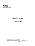
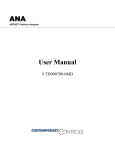
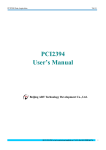
Appendix The Genius Serial Bus
C
This appendix describes the selection and operating characteristics of the bus cable that links Genius
devices. This information supercedes the equivalent text portion of chapter 2 of The Genius I/O System
and Communications Manual (GFK-90486), “The Communications Bus”.
A Genius serial bus consists of two or more Genius devices, and (usually) the bus cable that
connects them. A single block or bus controller with a Hand-held Monitor directly attached,
properly terminated with a 75 Ohm resistor, is considered the smallest possible Genius
communications bus.
Wiring Guidelines
Four types of wiring may be encountered in a typical factory installation:
1.
Power wiring - the plant power distribution, and high power loads such as high horsepower motors.
These circuits may be rated from tens to thousands of KVA at 220 VAC or higher.
2.
Control wiring - usually either low voltage DC or 120 VAC of limited energy rating. Examples are
wiring to start/stop switches, contactor coils, and machine limit switches. This is generally the
interface level of the Genius discrete I/O.
3.
Analog wiring - transducer outputs and analog control voltages. This is the interface level to Genius
I/O analog blocks.
4.
Communications and signal wiring - the communications network that ties everything together,
including computer LANs, MAP, and Genius I/O and communications bus.
These four types of wiring should be separated as much as possible to reduce the hazards from
insulation failure, miswiring, and interaction (noise) between signals. A typical PLC system with
Genius I/O may require some mixing of the latter three types of wiring, particularly in cramped
areas inside motor control centers and on control panels. In general, it is acceptable to mix the
Genius bus cable with the I/O wiring from the blocks, as well as associated control level wiring.
All noise pickup is cumulative, depending on both the spacing between wires, and the distance
span they run together. I/O wires and Genius bus cable can be placed randomly in a wiring trough
for lengths of up to 50 feet. If wiring is cord-tied (harnessed), do not include the bus cable in the
harness, since binding wires tightly together increases the coupling and mechanical stress that can
damage the relatively soft insulation of some serial cable types.
Wiring external to equipment and in cable trays, should be separated following NEC practices. The
pickup over long-distance runs with adequate spacing consists of common mode and ground
voltage differences. These are rejected due to the differential transmission mode of the Genius bus
and the bus isolation transformers built into each Genius I/O block.
GFK-0825F
C-1
C
Electrical Interface
The Genius serial bus uses computer grade twisted pair data cable. The half duplex token sequence
used requires only a single pair since at any time only one station is transmitting and all others are
receiving. All stations must receive in order to track the present token value and take their
appropriate turn on the bus, regardless whether the data is to be used locally. The transmit sequence
is the same as the serial bus address (SBA) set into each location during configuration. A
simplified interface circuit is shown below:
Wiring Terminals
+ REF
SER1
R
LOCAL
SUPPLY
SER2
COMP
RX+
COMP
RX-
+5 to 10 V
SHIELD
OUT
SER1
- REF
SER2
SER2
SHIELD
IN
TX+
R
TX-
ISOLATION
LOCAL
COMMON
INTERFACE
LOGIC
CHASSIS
GROUND
Signal coupling to the bus is via a high frequency, high isolation pulse transformer. This permits
the bus and the local logic to be at different voltage levels. The pulse waveforms are bipolar (see
next section below) to reduce DC baseline offsets in the waveform.
The daisy-chained bus is shown on the left in the above illustration. The SER 1 and SER 2 lines
are merely tapped at the intermediate locations along the bus. These connections must be consistent
since the signal is polarized. The shield of the cable is broken into segments at each location. Each
shield segment is DC grounded at one end (SHIELD OUT), and terminated with a small capacitor
at the other (SHIELD IN). The segmenting breaks up long ground loop paths. The capacitor
termination reduces common mode noise from high frequency pickup, while preventing large
ground loop currents in the shield at low frequencies.
The alternately switching transistors produce a negative pulse followed by a positive pulse across
SERIAL 1 relative to SERIAL 2. The bit waveform is a series of these pulses, as will be shown
later. The transformer provides isolation (2500 volts test) between the bus and the local logic,
permitting these to be at different voltages. The internal resistors in each line provide current limit
and some termination function during transmission.
The balanced (differential) signals on the twisted pair provide high noise immunity due to the
magnetic (H field) cancellation effect of the twisting, as well as electric (E field) reduction by the
shielding. Most remaining noise pickup is common mode: the transformer provides a high common
mode noise rejection by looking only at the differential signal across the SER 1-2 lines. The two
input comparators detect the positive polarity input pulses separately from the negative; these are
sent to a custom interface logic chip which digitally filters these for timing and sequence, then
reconstructs the NRZ digital data. Voltages between the two thresholds are ignored. This filtering,
and the high input threshold if the comparators, are highly effective in rejecting both random
impulse noise and low level line reflections. Finally a CRC-6 checksum check is performed before
the data is sent to the local processor (not shown).
C-2
Field Control™ Genius® Bus Interface Unit User’s Manual – October 1999
GFK-0825F
C
Genius Transceiver Electrical Specification
Property
Min
Max
Normal peak voltage Vp into 78 ohm terminated cable (1)
3.5 volts
5.5 volts
Normal peak voltage Vp into 150 ohm terminated cable (1)
6.0 volts
9.5 volts
Rated bus impedance (2)
78 ohms
150 ohms
Maximum output voltage (SER 1 and 2 open) (3)
Peak
RMS
35 volts
15 volts
Maximum output current (SER 1 and 2 shorted together) Peak
RMS
180 milliamp
50 milliamp
Transmitter source resistance
80 ohms
Transmitter source inductance (transformer leakage inductance)
10 microhenries
Receiver input threshold; +Vr, -Vr (4)
Receive mode input impedance
Receive mode load inductance (transformer shunt inductance)
140 ohms
0.7 volt
1.1 volt
10 K ohm
6 millihenries
Receiver common mode rejection (DC to 1 MHZ)
12 millihenries
60 dB
Shield capacitor termination
0.1 microfarad
Isolation, serial bus to circuit, continuous
240 volts AC
Notes:
(1) Vp may vary among various module types.
(2) Rated load is half cable impedance when termination is included.
(3) Peak open circuit voltage contains underdamped ringing due to lack of termination.
(4) Input voltages between +Vr and -Vr thresholds are ignored.
GFK-0825F
Appendix C The Genius Serial Bus
C-3
C
Selecting a Cable Type
The Genius bus is a shielded twisted-pair wire, daisy-chained from block to block and terminated at both ends.
Proper cable selection is critical to successful operation of the system.
Each bus in the system can be any cable type listed in the table below. Do not mix cables of different impedance,
regardless of cable run length. Do not mix cable types in long and/or noisy installations. Other, small-size twisted
pair shielded wire of unspecified impedance can be used for short runs of 50 feet or less, using 75 ohm terminations.
Selection of wire type may be limited by local and national codes and industry standards. Consult the cable
manufacturer to determine the cable's suitability for a particular type of installation.
Conservative wiring practices and national and local codes require physical separation between control circuits and
power distribution or motor power. Refer to sections 430 and 725 of the National Electric Code.
Cable #
& Make
NEC
(USA)
Type
Outer
Diameter
Terminating
Resistor*
-10%to+20%
1/2 Watt
Number of
Conductors/
AWG
Dielectric
Voltage
Rating
Ambient
Temp
Rating,
Deg. C
153.6s
153.6e
76.8
38.4 •
(A)9823
(C)4596
(M)M39240
(B)89182
none
CL2
CM
CL2P
.350in
8.89mm
150 ohms
2 / #22
30V
60
2000ft
606m
3500ft
1061m
4500ft
1364m
7500ft
2283m
150 ohms
2 / #22
150V
200
(B)9841
(M)M3993
(A)9818C
(B)9207
(M)M4270
(A)9109
(B)89207
(C)4798
(M)M44270
(A)9818D
(B)9815
(O)911264
**
(E)532185
BBDN
(A)9818
(B)9855
(M)M4230
(A)9110
(B)89696
(B)89855
(A)9814C)
(B)9463
(M)M4154
(A)5902C
(B)9302
(M)M17002
CM
CL2
CL2
CM
CM
CL2P
CM
*
CMP
none
*
none
.322in
8.18mm
.270in
6.86mm
.330in
8.38mm
120 ohms
2 / #24
30V
80
100 ohms
2 / #20
300V
80
2000ft
606m
1000ft
303m
1500ft
455m
3500ft
1061m
1500ft
455m
2500ft
758m
4500ft
1364m
2500ft
758m
3500ft
1061m
7500ft
2283m
3500ft
1061m
6000ft
1818m
.282in
7.16mm
100 ohms
2 / #20
150V
200
1500ft
455m
2500ft
758m
3500ft
1061m
6000ft
1818m
.330in
8.38mm
.260in
6.60 mm
approx .50in
(12.7mm)
.315in
8.00mm
100 ohms
2 / #20
100 ohms
2 / #22 flexing
250V
80
100 ohms
>150V
80
100 ohms
4 pairs #24
(solid)
4 (two pair) #22
150V
60
1500ft
455m
1500ft
455m
1500ft
455m
1200ft
364m
2500ft
758m
2000ft
606m
2000ft
606m
1700ft
516m
3500ft
1061m
3000ft9
09m
3000ft
909m
3000ft
909m
6000ft
1818m
4500ft
1364m
4500ft
1364m
4500ft
1364m
.274in
6.96mm
100 ohms
4 (two pair) #22
150V
200
1200ft
364m
1700ft
516m
3000ft
909m
4500ft
1364m
.243in
6.17mm
75 ohms
2 / #20
150V
60
800ft
242m
1500ft
455m
2500ft
758m
3500ft
1061m
.244in
6.20mm
75 ohms
4 (two pair) #22
300V
80
200ft
60m
500ft
152m
1200ft
333m
2500ft
758m
Notes:
CM
*
CM
CM
none
CMP
CMP
none
CM
CL2
none
CM
CM
Maximum Length Cable Run,
feet/meters at baud rate
A = Alpha, B = Belden, C = Consolidated, E = Essex, M = Manhattan, O = Olflex
• = Limited to 16 taps at 38.4 Kbaud
* = not known
**= Suitable for applications requiring high flexibility, continuous flex or vibration.
NEC classes are based on data obtained from manufacturers and are subject to change. CANADIAN CEC codes are
generally similar. Other countries may vary. The serial bus can be treated as a Class 2 circuit when appropriate
wiring practices are followed. Maximum available bus lengths may be affected when installation requires the high
voltage rated CM (Communications) rating. CM types can replace CL2, but not vice versa.
C-4
Field Control™ Genius® Bus Interface Unit User’s Manual – October 1999
GFK-0825F
C
Serial Bus Waveforms
The actual waveforms seen on the cable depend on the cable impedance and the distance from the
station presently transmitting. A data “0” is a series of three AC pulses, while a “1”is no pulse.
+Vp
+Vr
-Vr
-Vp
“0”
“1”
1
t=
baud rate
“0”
“0”
“1”
SERIAL 1 VOLTAGE RELATIVE TO SERIAL 2
Use caution when connecting instrumentation to the bus. A differential probe or a summation of
two probes relative to ground is required. Inadvertent grounding of one side of the bus can cause
loss of data or data errors.
The pulse frequency is three times the baud frequency, for example 460.8 KHz at 153.6 Kb.
The peak transmitted voltage Vp and the receiver thresholds Vr are per the electrical specification
above. The peak voltages measured will decline with distance along the cable from the transmitting
station, so different stations will have varying amplitudes. The wave shape will also become more
rounded with distance.
The minimum amplitude pulses seen during a “0” should exceed the receiver threshold Vr of 900
millivolts by 50% (about 1.4 volts) for best reliability. An occasional pulse at or below the
threshold may still not cause the bit to be missed, due to a voting algorithm in the logic, however.
Likewise, no pulses greater than Vr should exist during logic “1” intervals. Occasional extra pulses
during this interval are also rejected by the logic.
Line reflections will show up as notch distortion during the pulse or low level pulses during “1”
intervals, and their appearance is synchronized to the baud frequency. These cause no problem if
they do not cause violation of the amplitude criteria of the previous paragraphs.
The Serial 1 and Serial 2 lines should always have a termination resistor equal to the characteristic
impedance of the cable connected at each extreme end. When testing a Genius block or other
device using a Hand Held Monitor, when no serial bus is present, a terminating resistor will
improve integrity. 75 Ohms is recommended.
GFK-0825F
Appendix C The Genius Serial Bus
C-5
C
Using Other Cable Types
The cable types listed in the preceding table are recommended for use. If the cable types listed
above are not available, the cable selected must meet the following guidelines.
1.
High quality construction. Most important is uniformity of cross section along the length of the
cable. Poor quality cable may cause signal distortion, and increase the possibility of damage
during installation.
2.
Precision-twisted shielded wire of EIA RS422 standard type, having a uniform number of
twists per unit of length. In a catalog, this type of cable may also be listed as twinaxial cable,
data cable, or computer cable.
3.
Relatively high characteristic impedance; 100 to 150 ohms is best; 75 ohms is the minimum
recommended.
4.
Low capacitance between wires, typically less than 20pF/foot (60pF/meter). This may be
accomplished by inner dielectrics of foamed type, usually polypropylene or polyethylene,
having a low dielectric constant. Alternatively, the conductors may be spaced relatively far
apart. Lower impedance types have smaller cross-sections, and provide easier wiring for
shorter total transmission distances.
5.
Shield coverage of 95% or more. Solid foil with an overlapped folded seam and drain wire is
best. Braided copper is less desirable; spiral wound foil is least desirable.
6.
An outer jacket that provides appropriate protection, such as water, oil, or chemical resistance.
While PVC materials can be used in many installations, Teflon, polyethelene, or
polypropylene are usually more durable.
7.
Electrical characteristics: cable manufacturers' information about pulse rise time and NRZ data
rate is useful for comparing cable types. The Genius bit consists of three AC pulses; the
equivalent NRZ bit rate is about three times as great.
For assistance in selecting a specific cable type, please consult your local GE Fanuc application
engineer.
Prefabricated Cables
For applications using 150 ohm cables, prefabricated cables are available in 15" (IC660BLC001)
and 36" (IC660BLC003) lengths. These cables terminate in mating connectors that simplify wiring
between I/O blocks. The 36" cable is recommended for Field Control installations.
SHD SHD SER SER
OUT IN
2
1
C-6
Field Control™ Genius® Bus Interface Unit User’s Manual – October 1999
GFK-0825F
C
Effect of Long Cables, Repeaters, or Unspecified Cable Types On Maximum Length Bus
Three effects limit the maximum length bus available at any baud rate:
1.
Voltage attenuation
2.
Waveform distortion (frequency dispersion)
3.
Propagation delays
Attenuation
The transmitter output levels and receiver thresholds determine the maximum attenuation that can
be tolerated. For Genius products, this is the principal determinant when using recommended cable
types.
Distortion
Waveform distortion is due to the limited bandwidth of wire media, which causes the various
frequency components of a pulse waveform to travel at different speeds and thus arrive separately
in time (called dispersion). As a result, the received pulse appears rounded and distorted. The signal
at the extreme end from the transmitter may look rounded and skewed as shown below. Distortion
is most apparent near the beginning and end of a pulse train where in may appear as a change in
phase or a frequency shift. Critical timing for a logic 0 transmission is shown below in a more
detailed version of the waveform:
Tw
Tw
+Vr
-Vr
Tp/2
Tp/2
Note the first and last half-cycle look wider. The most critical to operation is the first full cycle of
the first start bit of the transmission. Detection of this pulse establishes the time synchronization of
the receiver to the incoming waveform. Missing this first pulse does not cause the data to be
missed, but may compromise the noise immunity with respect to extra or missing pulses. The
frequency of the AC pulse is 3X the baud rate as noted earlier. This means the normal period
Tp(normal) is:
GFK-0825F
•
2.17 microseconds at 153.6 Kb
•
4.34 microseconds at 76.8 Kb
•
8.68 microseconds at 38.4 Kb.
Appendix C The Genius Serial Bus
C-7
C
The half cycle pulse width, when measured between the positive and negative receiver thresholds,
denoted as Tp/2 in the figure, will vary along the waveform due to dispersion, and resembles a
frequency shift.. The digital input filter essentially is a band pass filter which looks at the half cycle
timing Tp/2, and the duration above the thresholds, Tw. The limits are:
•
Tp/2 = 0.6 Tp(normal) maximum
•
Tw = 0.188 Tp(normal) minimum
These measurements can be taken when evaluating the maximum length of an unspecified cable.
Dispersion is much less of a problem with fiber optic links since the media is much wider
bandwidth, and therefore has less distortion.
Propagation Delay
The propagation delay is caused by travel time of the signal down the cable. Typical signal velocity
in data grade cables is around 65- 78% of the speed of light. This requires about 3 microseconds to
travel a 2000 foot long bus. This is about half a bit time at 153,6 Kb. This skew could affect the
bus access sequence since only one bit of quiet bus (skip) time is usually allocated between
transmission of adjacent addresses. (Refer to Bus Access Time section below.) The signal must
reach all devices on the bus within the period of one bit. Propagation delay causes the ultimate
limitation in bus length, even with ideal media. Propagation speed through fiber optic is not
significantly different than wire, and delays through the interfaces must be accounted for.
Serial Data Format
The Genius protocol is designed to produce maximum throughput of data by using a minimum
overhead of control and synchronizing characters.
Each character is 11 bits long, comprising a start bit (always 0), next a control bit, followed by 8
bits of data, sent LSB first. The last bit is a stop bit, always 1. Successive characters are sent with
no time space between them. The control bit is used to signal the type of character being sent. A 1
indicates a control character, and 0 a data character.
A minimum transmission is comprised of a start character, one or more data characters, and a stop
character. The Start character data contains the address and whether the transmission is directed to
a specific address or a broadcast to all. The End character contains the CRC-6 checksum. More
complex transmissions may have additional start and end of block characters to break up the
message into “blocks” of data (not to be confused with Genius I/O “Blocks”). For example, a Bus
Controller can send device specific messages (blocks of data) to all devices on the bus during one
transmission cycle.
C-8
Field Control™ Genius® Bus Interface Unit User’s Manual – October 1999
GFK-0825F
C
Bus Access
All devices must receive the current SBA and the stop character even though the data is irrelevant
locally. After the stop control character is received, each device on the bus starts a timer. The time
delay is equal to a “skip time” times the difference between the device Serial Bus Address (SBA)
and the last SBA received. The device will transmit after the time delay if no other start bits are
detected first. Thus each device takes turn in order of SBA. Unused SBAs result in longer times
between messages. All devices must detect messages within this skip time delay. A bus “collision”
(two sources transmitting simultaneously) results if this sequence is missed. The skip time value is
equal to one bit period, except on the 153.6e rate, where it is two bit periods long. The longer
interval is useful to accommodate the longer propagation delays due to longer bus cables, or when
delays are introduced by fiber optic or other repeaters, The worse case is when adjacent SBAs are
physically located at opposite ends of a long bus. For example, assume SBA 4 and 6 are at one end
of a 2000 foot bus and SBA5 at the other, operating at 153.6s Kb. When SBA 4 end character is
detected, SBA6 immediately starts timing 2 skip times (13 uSec) to start of it's transmission. SBA5
receives the end character 3 uSec later, and starts timing 1 skip time (6.5 uSec). Thus SBA 5 will
start transmitting 9.5 uSec after SBA 4 quit. This allows 3.5 uSec for the signal to get back to
SBA6 to cancel its transmission turn. The 3 uSec transmission delay leaves only 0.5 uSec to do this
and avoid a collision between SBA5 and 6.
Bus collisions result in missing data or detected CRC errors. Problems resulting from bus collisions
can be fixed by not using (skipping) a SBA, resequencing SBAs in order along the bus, going from
153.6s baud to the 153.6e, or a lower baud rate.
GFK-0825F
Appendix C The Genius Serial Bus
C-9
C
Bus Length
The maximum bus length for shielded, twisted-pair cable is 7500 feet. Some cable types are
restricted to shorter bus lengths. In turn, the bus length determines which baud rate may be
selected.
If the application requires greater bus length, fiber optics cable and modems can be used, as
explained later in this chapter.
Bus Length and Baud Rate for Busses with Phase A Devices
If a bus has any Phase A Genius products (catalog numbers IC660CBDnnn, IC660CBSnnn,
IC660CBAnnn, IC660HHM500, or IC660CBB900/901), the bus must use 153.6 Kbaud “standard” and
the maximum bus length is 2000 feet. Therefore, only the cable lengths listed under “153.6s” are
permitted (“153.6e” refers to 153.6 Kbaud extended, which is not compatible with 153.6 Kbaud
standard).
Baud Rate Selection
A Genius I/O or communications bus can operate at one of four baud rates:
153.6 Kbaud standard, 153.6 Kbaud extended, 76.8 Kbaud, or 38.4 Kbaud.
Follow these guidelines when selecting the baud rate for a bus:
1.
All devices on a bus must operate at the same baud rate (other busses in the system may
operate at different baud rates).
2.
If there are any older Genius products on the bus (catalog numbers IC660CBDnnn,
IC660CBSnnn, IC660CBAnnn, IC660HHM500, or IC660CBB900/901), the bus must be set
up to use 153.6 Kbaud standard.
3.
If the cable length is between 4500 and 7500 feet, you must select 38.4 Kbaud. This data rate
only supports a maximum of 16 device on the bus.
4.
If the cable length is between 3500 and 4500 feet, select 76.8 Kbaud.
5.
If cable length is between 2000 and 3500 feet, select 153.6 Kbaud extended.
6.
If the cable length is less than 2000 feet, either 153.6 Kbaud standard or 153.6 Kbaud extended
can be used. The products are set to operate at 153.6 Kbaud standard when shipped from the
factory. The use of 153.6 Kbaud extended is recommended, especially if the system will
include a dual bus with Bus Switching Modules.
In noisy environments, 153.6 Kbaud extended provides improved noise immunity with little effect
on bus scan time. If a system is experiencing excessive blinking of the bus controller's COMM OK
light, or if the I/O blocks' I/O Enabled LEDs go off frequently, 153.6 Kbaud extended should be
used.
The baud rate selected should be indicated on all blocks, especially if different busses in the facility use
different baud rates. Before connecting a Hand-held Monitor to a functioning bus, check that it has been
configured to the correct baud rate. If not, change the HHM baud rate selection, turn off the HHM,
connect it to the bus, then turn the HHM on.
C-10
Field Control™ Genius® Bus Interface Unit User’s Manual – October 1999
GFK-0825F
C
Bus Ambient Electrical Information
Most capacitively- and magnetically-coupled noise shows up as common mode voltage on the bus.
The bus provides a 60 dB common mode rejection ratio. A noise spike above 1000 volts would be
required to corrupt the data. The bus receivers filter out corrupted data and perform a 6-bit cyclic
redundancy check to reject bad data. Corrupted signals due to noise show up as missed data rather
than incorrect data. The bus continues operating to the maximum extent possible when bus errors
are detected; random bus errors do not shut down communications. Bad data is rejected by the
receiving device and excessive errors are reported to the controller. Bus errors are indicated by
flickering of I/O block and bus controller LEDs. If excessive bus errors occur, the problem should
be found and corrected.
Lightning Transient Suppression
Running the bus cable outdoors or between buildings may subject it to lightning transients beyond
the 1,500 volt transient rating of the system. Installing cable underground reduces the probability of
a direct lightning strike. However, buried cables can pick up hundreds of amperes of current when
lightning contacts the ground nearby.
Therefore, it is important to protect the installation by including surge protectors on underground
data lines. The cable shields should be grounded directly. Surge suppressors and spark gaps should
be used to limit the voltage that might appear on the signal lines. It is recommended to install two
(only) silicon surge suppressors or spark gaps to control transients of 1 to 25 Kilovolts from 100 to
1000 amps or more. These devices should be installed close to the entrance of the bus to the
outdoors.
Silicon Surge Suppressors are available many sources, including Clare/General Instruments and
Motorola, For information about this product, in the US contact Lucas Industries Incorporated,
5500 New King Street, Troy, Michigan 48098 (tel: 313 879-1920, fax: 313 552-1020). Spark gaps
are available from Clare. Refer to the vendor's literature for installation details.
In extreme situations, such as totally-isolated power systems, additional protection against
lightning damage should be provided by adding surge suppressors for groups of I/O blocks. Such
suppressors should be installed from incoming power leads to ground (enclosure baseplate/block
case where leads enter the enclosure).
A device specifically designed to protect the Genius bus is available from CONTROL
TECHNOLOGY, 835 Hwy 90, Hancock Square Suite 10 (P. O. Box 2908), Bay Saint Louis, MS
39520. (tel 601 466-4550, fax 601 466-4553). Contact them for application information. The
devide must be used in combination with power line suppression to fully protect the system.
GFK-0825F
Appendix C The Genius Serial Bus
C-11
1
The Genius Bus
The Genius bus is a shielded twisted-pair wire, daisy-chained between devices, and
terminated at both ends. Proper cable selection is critical to successful operation of
the system. Suitable cable types are listed in the Genius I/O System User’s Manual.
Conservative wiring practices, as well as national and local codes, require physical
separation between control circuits and power distribution or motor power. Refer to
sections 430 and 725 of the National Electric Code.
Bus Type
Daisy-chained bus cable; single twisted pair plus shield or Twinax.
Fiber optics cable and modems can also be used.
Bus
Termination
75, 100, 120, or 150 ohm resistor at both ends of electrical bus
cable.
Baud Rate
Configurable. 153.6 Kbaud standard, 153.6 Kbaud extended, 76.8
Kbaud, or 38.4 Kbaud.
Maximum Bus
Length
7500 feet at 38.4 Kbaud, 4500 feet at 76.8 Kbaud, 3500 feet at
153.6 Kbaud extended, 2000 feet at 153.6 Kbaud, standard.
Maximum length at each baud rate also depends on cable type.
Chapter 2 provides a complete list of cable types, showing
corresponding bus lengths and baud rates.
Greater bus lengths are possible using sections of fiber optics cable
with modems.
GFK-2017
Maximum
Number of
Devices
32 devices at 153.6 Kbaud standard, 153.6 Kbaud extended, or 76.8
Kbaud. 16 devices at 38.4 Kbaud. Includes bus controller and
typically a Hand-held Monitor.
Data Encoding
Each bit is encoded into three dipulses, majority voted at the
receiver to correct any single dipulse errors. A dipulse is an AC
code consisting of a positive then negative excursion of voltage.
Dipulses are individually sampled to reject low and high frequency
interference.
Modulation
Technique
Frequency Shift Keying (FSK) 0 to 460.8 KHz max. (153.6 Kilobaud)
Isolation
2000 volts Hi-Pot, 1500 volts transient common mode rejection.
Signal/noise
Ratio
60 db
Chapter 1 Introduction
1-5