1
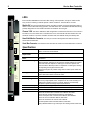
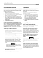
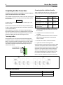
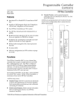
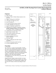
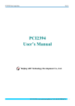
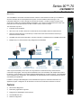
Series 90™-70
IC687BEM731
Genius Bus Controller
GFK-2370
March 2010
The IC687BEM731 Genius Bus Controller interfaces a Genius communications bus with up to 31 additional
devices to a Series 90-70 or PACSystems RX7i system. It can be installed in slots 2 through 17 in a
PACSystems RX7i PLC or slots 2 through 9 in a Series 90-70 system. The Bus Controller occupies only a
single slot in a VME-type or standard-width PLC backplane. If it is used in a standard Series 90-70 PLC rack,
there will be a 0.8-inch space between the Bus Controller and the module to its right.
OK
CH1
OK
The Genius bus may serve:
▪
▪
▪
▪
▪
Individual Genius I/O Blocks.
Other PLCs such as: RX7i, Series 90-70, Series 90-30, and VersaMax, Series Six and Series Five.
Series 90-70 Remote Drops. A remote drop is a Series 90-70 rack that is interfaced to the bus by a
Remote I/O Scanner module.
VersaMax and Field Control I/O Stations. This Bus Controller is compatible with the VersaMax Genius NIU.
Multiple hosts, for communications using datagrams and Global Data.
Series 90-70 PLC
with Genius Bus
Controller,
IC687BEM731
PC with PCIbased
PCIM Board
PACSystems
RX7i with
Genius Bus
Controller,
IC687BEM731
Genius
I/O
Blocks
VersaMax I/O Station with
Genius Network Interface Unit
Series 90-30 PLC
with Genius Bus Controller
PACSystems RX3i
with Genius Bus Controller
Series 90-70 I/O Station with
Remote I/O Scanner Module
A bus may be used entirely for I/O control, or it may feature I/O control enhanced by communications
commands in the program. A bus may also be dedicated to CPU communications, with multiple CPUs and no
I/O devices. Communications can include transmitting Global Data from one CPU to another. The Global Data
area is identified in the configuration. After initialization, the specified data area is transferred between devices
automatically and repetitively.
In addition, messages called Datagrams can be transmitted in response to individual commands in the
application program. Datagrams can be directed to one device or broadcast to all devices on the bus.
Features
▪ Advanced I/O Diagnostics
▪ Redundancy applications supported
▪ Datagrams and Global Data communications
▪ Hand Held Monitor Port
▪ Software configuration
GENIUS
BUS
CONTROLLER
2
Genius Bus Controller
GFK-2370C
LEDs
Bus Controller IC687BEM731 has three LEDs. During normal operation, the top two LEDs are ON.
They are OFF or blinking to indicate special or failure conditions. The third LED is not used.
Module OK: The top LED indicates the status of the Bus Controller. If powerup diagnostics detect a
failure or if the module fails during operation, this LED will be OFF. The Module OK LED blinks during
powerup diagnostics or when the Bus Controller is installed in the wrong slot.
Channel 1 OK: This LED is ON after a valid configuration is received from the CPU. In the event of a
BEM731
MODULE OK
CHANNEL 1 OK
NOT USED
ON = OK
MODULE FUNCTION
GENIUS BUS
CONTROLLER
(1 CHANNEL)
bus failure, such as a broken wire or excessive bus errors, the Channel1 OK LED remains OFF until
the failure condition is corrected. If the Bus Controller fails, the LED will remain permanently OFF.
Hand-Held Monitor Connector: The nine-pin connector directly below the LEDs is used for a
Genius Hand-held Monitor.
Serial Bus Connector: Connections to the serial bus are made to the removable bottom connector.
Specifications
HAND
HELD
MONITOR
Devices on the bus
32 devices at 153.6 Kbaud standard, 153.6 Kbaud extended, or 76.8
Kbaud. 16 devices at 38.4 Kbaud.
Module Current
Requirement
1.3 Amps from the backplane +5V supply
Communications
Rates
Configurable: 153.6 Kbaud extended, 153.5 Kbaud standard, 6.8 Kbaud,
38.4 Kbaud
Maximum Bus Length
7500 feet at 38.4 Kbaud, 4500 feet at 76.8 Kbaud, 3500 feet at 153.6
Kbaud extended, 2000 feet at 153.6 Kbaud, standard. Maximum length at
each baud rate also depends on cable type. The Genius System and
Communciations Manual provides a complete list of cable types, showing
corresponding bus lengths and baud rates.
Greater bus lengths are possible using sections of fiber optics cable with
modems.
Bus Type
Daisy-chained bus cable; single twisted pair plus shield or Twinax. Fiber
optics cable and modems can also be used
Bus Termination
75, 100, 120, or 150 ohm resistor at both ends of electrical bus cable.
Data Encoding
Each bit is encoded into three dipulses, majority-voted at the receiver to
correct any single dipulse errors. A dipulse is an AC code consisting of a
positive then negative excursion of voltage. Dipulses are individually
sampled to reject low and high frequency interference.
ModulationTechnique
Frequency Shift Keying (FSK) 0 to 460.8 KHz max. (153.6 Kilobaud)
Isolation
2000 volts Hi-Pot, 1500 volts transient common mode rejection.
Signal/noiseRatio
60 db
Related Documents
Series 90-70 Genius Bus Controller User’s Manual, GFK-2017.
Genius Analog and Discrete Blocks Manual, GEK-90486-2
Genius I/O System and Communications Manual, GEK-90486-1.
Series 90-70 PLC Installation Manual, GFK-0262.
Series 90-70 Remote I/O Scanner User’s Manual.
The PACSystems RX7i Installation Manual, GFK-2223
Proficy Machine Edition Logic Developer-PLC Getting Started, GFK-1918
CH 1
CHANNEL 1
SER1
SER2
SHIELD
IN
SHIELD
OUT
MODULE
IC687BEM731
LABEL
44A739865 005
Genius Bus Controller
3
GFK-2370C
Installing the Bus Controller
Configuration
The Bus Controller can be installed at any position on the Genius
bus.Communications are most efficient if devices are placed in the
same sequence as their configured Device Numbers. The Bus
Controller is usually device 31.
The Bus Controller and the devices on its bus must be
configured as part of the PLC system using the
Machine Edition Logic Developer 5.0 Service Pack 2 or
later software.
1.
Be sure the rack is powered down.
2.
Position the Bus Controller at its intended location.
The devices on the bus must also be configured
separately. This includes:
3.
Push the Bus Controller into the card guide until it is aligned
with the connector on the rack backplane.
4.
Push the module into the connector until it clicks onto the
rack rails. Be sure that the board has seated properly in the
connector. Tighten screws at the top and bottom to hold the
module in place.
5.
Complete the bus connections.
After the installation is completed and power is applied, the Bus
Controller start up and blink the top LED for about 5 seconds.
When the diagnostics have completed successfully, the top LED
stays ON. The middle LED lights when a valid configuration for
the module has been received from the CPU, and the bus
operation has been verified. The bottom LED is OFF under all
conditions.
Removing the Bus Controller
1.
Power down the rack in which the Bus Controller is located.
Before removing power, it is important to consider the impact
on the controlled process.
2.
If the PLC is not part of a redundant system, the bus wiring
can be removed from the Bus Controller.
If the PLC is part of a redundant system and another CPU
on the bus is now functioning as the controller, the Bus
Controller can be removed without powering down the bus.
Do not disconnect the bus cable or any terminating resistor
from the Bus Controller’s bus connector. Remove the
connector from the Bus Controller very carefully. Avoid
contact with exposed cable wiring. Place the terminal
assembly with the bus wiring still attached, in a protected
location.
Caution
If exposed wiring comes in contact with conductive
material, data on the bus may be corrupted, possibly
causing the system to shut down.
3.
To remove the Bus Controller, loosen any screws attaching it
to the rack and then hold the top and bottom plastic tabs to
disengage them from the rack rails.
4.
Pull the board firmly to remove it from the backplane.
5.
Slide the board outward to remove it from the rack.
A.
Configuring I/O blocks with a Hand-held Monitor
and/or Write Configuration COMMREQs. For a
Series 90-70 or PACsystems RX7i PLC, certain
blocks can be configured directly from the
programmer on an operating Genius bus.
B.
Configuring Remote Drops with the programming
software.
C.
Configuring redundant Bus Controllers with the
programming software
Setting the Bus Controller Baud Rate
The Genius network can be configured to operate at
one of four speeds, up to 153.6K baud.
The default baud rate of 153.6 Kbaud (standard)
supports a bus up to 2,000 feet in length. If the bus is
longer than 2,000 feet, a lower baud rate must be
selected, following the guidelines in the Genius System
and Communications Manual. The maximum length of a
network depends on the baud rate and cable type; it
can be up to 7,500 feet.
Fiber optics cable with modems can be used for long
distance requirements or if additional isolation is
required.
Caution
Select the same baud rate for the Bus Controller as that
used for other devices on the bus. The bus will not
operate unless all devices are set to the same baud
rate.
The Bus Controller powers up with no assumed baud
rate or serial bus address. After a valid configuration
has been stored to the system, the PLC CPU transfers
the new configured baud rate and serial bus address to
the module at the conclusion of the store and each time
the Bus Controller is power-cycled.
4
Genius Bus Controller
GFK-2370C
Completing the Bus Connections
Connecting the Bus to the Bus Controller
For details of bus selection and installation, refer to the Genius
System and Communications User’s Manual.
There will always be 2 bus wires or one bus wire and a
resistor lead in each terminal. Example specifications
are:
Using shielded, twisted pair cable, create a serial bus connecting the
Bus Controller, I/O blocks, and other permanently installed devices
as shown below.
Caution
All cable used for one serial bus must be of the same type, or the
bus will not work.
Other busses connected to the same CPU may use different types
of cable. Cable specifications are found in the Genius System and
Communications Manual.
When making bus connections, the maximum exposed length of
bare wires should be two inches. For added protection, each shield
drain wire should be insulated with spaghetti tubing to prevent the
Shield In and Shield Out wires from touching each other.
Terminating the Bus
Each physical end of a bus must be terminated with appropriate
termination resistors, as explained in the Genius I/O System User’s
Manual. If the Bus Controller is located at the end of a bus, install
the appropriate resistor across its Serial 1 and Serial 2 terminals.
The amount of resistance required will depend upon the type of
cable used for the bus.
Terminating the Bus
at the Bus Controller
Serial 1
2 conductors with same cross
section, solid
0.08 mm²
minimum
0.5 mm²
maximum
2 conductors with same cross
section, flexible
0.08 mm²
minimum
0.75 mm²
maximum
2 conductors of the same cross
section, flexible, ferrules without
plastic sleeve,
0.25 mm²
minimum
0.34 mm²
maximum
2 conductors of the same cross
section, flexible, TWIN ferrules
with plastic sleeve
0.5 mm²
minimum
0.5 mm²
maximum
1.
Using a small flathead screwdriver, loosen thebus
connector mounting screws and remove it from the
Bus Controller.
2.
Complete the bus connections for the Bus
Controller.
3.
Tighten the individual terminal screws to hold each
pair of wires in place. Maximum recommended
torque is 0.22Nm.
4.
Re-insert the connector on the Bus Controller,.
5.
Tighten the connector mounting screws.
Connect the Serial 1 terminal of each device to the Serial
1 terminals of the previous device and the next device.
Connect the Serial 2 terminal of each device to the Serial
2 terminals of the previous device and the next device.
Shield In of each device must be connected to Shield
Out of the preceding device. For the first device on the
bus, Shield In can be left unconnected. For the last
device on the bus, Shield Out can be left unconnected.
Serial 2
Ordering Information
Description
Catalog Number
Series 90-70 Genius Bus Controller, VME-Width
IC687BEM731
Blank-slot filler, VME-width
IC698ACC735