1
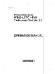
Digital Controller
ES100X/P
Intelligent, User-friendly
Digital Controller and Programmer
Controlled with ease with a support software which
is input via the communication jack on the front
panel.
Minute adjustment of PID parameters can be done
easily using fuzzy fine-tuning.
Any available functions can be assigned to the front
keys to make an optimum MMI (Man Machine
Interface) that displays the items required by the
user.
The incorporated hybrid control (advanced PID and
fuzzy logic) function makes high-precision control
possible.
Both cascade and proportional position control can
be performed using a single controller. (Models with
secondary inputs have been added for the ES100P
as well.)
RC
Analog and digital processing can be combined.
400 steps max. are possible with the ES100P (99
program patterns, 99 steps).
Ordering Information
These models are not provided with a Control Output Unit. Be sure to specify the Control Output Unit when ordering.
Temperature/Process Controllers
ES100X Controller
Standard and Heating/Cooling Controllers*
Transmission
output
None
4 to 20 mA
Communications
None
Aux. I
Aux. O
Open
collector
Relay
RS-232C
0
3
3
8
0
0
2
8
2
2
2
RS-422/485**
2
Without analog
input 2
ES100X-AAH
ES100X-AAHFB
ES100X-AAHFD
ES100X-AAHFE
ES100X-AAH01FE
ES100X-AAH04FE
With analog input 2
(4 to 20 mA or 1 to
5 V)
---
ES100X-AAWHFB
---
ES100X-AAWHFE
ES100X-AAWH01FE
ES100X-AAWH04FE
Proportional Positioning Controllers***
Transmission output
4 to 20 mA
Communications
Aux. I
Aux. O
Open
collector
Relay
None
RS-232C
3
3
8
0
2
8
2
2
RS-422/485**
2
Without analog input 2
ES100X-RRPFB
ES100X-RRPFD
ES100X-RRPFE
ES100X-RRP01FE
ES100X-RRP04FE
With analog input 2
(4 to 20 mA or 1 to 5 V)
ES100X-RRPWFB
---
ES100X-RRPWFE
ES100X-RRPW01FE
ES100X-RRPW04FE
*Factory-set to standard operation.
**Factory-set to RS-422 communications.
***An Output Relay Unit is mounted at the factory.
7
ES100X/P
ES100X/P
ES100P Programmer
Standard and Heating/Cooling Controllers*
Transmission
output
None
4 to 20 mA
Communications
Aux. I
Aux. O
Open
collector
Relay
None
RS-232C
0
3
8
0
2
8
2
2
RS-422/485**
2
Without analog
input 2
ES100P-AAH
ES100P-AAHFD
ES100P-AAHFE
ES100P-AAH01FE
ES100P-AAH04FE
With analog input 2
(4 to 20 mA or 1 to
5 V)
---
---
ES100P-AAWHFE
ES100P-AAWH01FE
ES100P-AAWH04FE
Proportional Positioning Controllers***
Transmission
output
4 to 20 mA
Communications
None
Aux. I
Aux. O
Open
collector
Relay
RS-232C
3
8
2
8
2
RS-422/485**
2
Without analog
input 2
ES100P-RRPFD
ES100P-RRPFE
ES100P-RRP01FE
ES100P-RRP04FE
With analog input 2
(4 to 20 mA or 1 to
5 V)
---
ES100P-RRPWFE
ES100P-RRPW01FE
ES100P-RRPW04FE
*Factory-set to standard operation.
**Factory-set to RS-422 communications.
***An Output Relay Unit is mounted at the factory.
Temperature Ranges
Thermocouples
Input
Range
R/S
K2
J1
J2
T
E
°C
0 to 1,700
–200 to 1,300
0.0 to 600.0
–100 to 850
0.0 to 400.0
–199.9 to 400
0 to 600
°F
0 to 3,000
–300 to 2,300
0.0 to 999.9
–100 to 1,600
0.0 to 750.0
–199.9 to 700
0 to 1,100
Input
Range
K1
B
N
L1
L2
U
W
PLII
°C
100 to 1,800
0 to 1,300
–100 to 850
0.0 to 400.0
–199.9 to 400
0 to 2,300
0 to 1,300
°F
300 to 3,000
0 to 2,300
–100 to 1,600
0.0 to 750.0
–199.9 to 700
0 to 3,000
0 to 2,300
Platinum Resistance Thermometers
Input
Range
JPt/Pt
°C
–199.9 to 600.0
°F
–199.9 to 999.9
Current/Voltage Input
Input
Range
Current
4 to 20 mA
0 to 20 mA
Voltage
0 to 10 mV
0 to
100 mV
Support Software (For Windows)
Name
Support Software (CD-ROM)
Model
ES100-YB177-E
Current Transformers (CT)
Model
E54-CT1
E54-CT3
Hole diameter
5.8 mm
12.0 mm
Note:
8
The E54-CT2 cannot be used.
–10 to
10 mV
0 to 1 V
1 to 5 V
0 to 5 V
0 to 10 V
ES100X/P
ES100X/P
Control Output Unit
ON/OFF
Output
p
Relay
y output
p
SSR output
p
Linear
12 VDC,
NPN
Model
Note:
E53-R
Current output
p
Voltage output (for driving SSR)
E53-S
E53-Q
24 VDC,
NPN
E53-Q3
Voltage
g output
p
24 VDC,
PNP
E53-Q4
E53-C3
E53-C3D
E53-V34
E53-V35
The E53-C cannot be used.
Product Inspection Sheet
Name
Model
Product Inspection Sheet
ES100-K
Cables
Name
Expansion I/O Cable
Model
For XW2B-20G, G7TC-OC08
G79-200C-175-ES1
For XW2B-34G (corresponding
to BCD communication)
XW2Z-200C
For G7TC-C08 (output only)
G79-200C-ES1
Cable for Support Software (see note.)
Note:
ES100-CT023-202 (9-pin)
Cable comes with support software.
Accessories
Name
Model
Watertight Cover
Y92A-96N
Terminal Cover
E53-COV01
Model Number Legend:
Controllers
ES100X -
1
2 3 4 5 6
7
1. Control Method and Outputs
AA: Standard, heating/cooling
RRP: Proportional positioning
2. Secondary Input
W:
Yes
3. Heater Burnout Detection
H:
Yes
4. Communications
01: RS-232C
04: RS-422/RS-485
5. Transmission Output
F:
Yes (4 to 20 mA)
6. Digital I/O
B:
Digital inputs only (3 points)
D:
Digital I/O (3 input points and
2 output point)
E:
Expansion digital I/O or BCD
(8 input points and output points
respectively)
7. Product Inspection Sheet
K:
Yes
5. Transmission Output
F:
Yes (4 to 20 mA)
6. Digital I/O
D:
Digital I/O
(3 input points and 2 output points)
E:
Expansion digital I/O or BCD
(8 input points and output points
respectively)
7. Product Inspection Sheet
K:
Yes
Programmers
ES100P -
1
2
3
4 5 6
1. Control Method and Outputs
AA: Standard, heating/cooling
RRP: Proportional positioning
2. Secondary Input
W:
Yes
3. Heater Burnout Detection
H:
Yes
4. Communications
01: RS-232C
04: RS-422/RS-485
7
9
ES100X/P
ES100X/P
Specifications
Ratings
Supply voltage
100 to 240 VAC, 50/60 Hz
Operating voltage range
85% to 110% of rated supply voltage
Power consumption
Approx. 20 VA (at 100 VAC) to 25 VA (at 240 VAC)
Analog input 1 (main input)
Current input: 4 to 20 mA, 0 to 20 mA (impedance: 150Ω±10%)
Voltage input: 1 to 5 V, 0 to 5 V, 0 to 1 V, 0 to 10 V, 0 to 10 mV, 0 to 100 mV, –10 to 10 mV
(impedance: 1 MΩ min.)
Thermocouple:R, S, K, J, T, E, B, N, L, U, PLII, W
Platinum resistance thermometer: Pt100, JPt100
Analog input 2
Current input: 4 to 20 mA (impedance: 150Ω±10%)
Voltage input: 1 to 5 V (impedance: approx. 1 MΩ)
CT input (see note 1)
Connect the dedicated CT (E54-CT1 or E54-CT3).
Potentiometer input (see note 1)
100 Ω to 2.5 kΩ
Control output (see note 2)
Output Unit (sold separately) (use the Output Unit to obtain a control output. The position
proportional output type, however, has Relay Output Units on its socket.)
Control mode
Hybrid of fuzzy logic and advanced PID control (2-PID) with auto-tuning and fine-tuning or
ON/OFF.
Auxiliary output
Relay output: two Independent outputs (SPDT and SPST-NO), 250 VAC, 3 A
Open collector output: common outputs, 24 VDC+10%/–15%, max. load current: 100 mA
Transmission output
1 output, 4 to 20 mA with a load of 600 Ω max.
External signal input
(auxiliary input)
Power supply: 24 VDC+10%/–15%,
(the model with expansion I/O needs an external power supply)
Current when the signal is ON:
3 mA max.
Leakage current when the signal is OFF: 0.3 mA max.
Setting method
Digital setting with Up and Down Keys or Support Software (via RS-232C terminal on the front
panel)
Indication method
Digital indications (character height: PV: 14.2 mm, SV: 10.2 mm, BANK, STEP, PTN: 7.6 mm)
(color PV: red, SV: green, BANK, STEP, PTN: yellow)
Bar graph indication (resolution: 10; color: green)
Status of ramp and soak (displayed by green LED (ES100P only))
Other functions
Manual output
Communications (RS-232C, RS-422/RS-485, BCD)
Assignments (front keys, setting/display items, digital I/O, and analog I/O)
Processing (four fundamental arithmetic operations, primary time-lag filters, linear
approximation, broken line approximation, extraction of a square root, logical operation,
average addition, average movement)
ON/OFF timer
Heating and cooling control (except the Proportional Positioning Model)
SP setting limiter, SP rise/fall rate limiter, MV (output) change rate limiter, key protect selection
etc.
8 banks (set value, event output, PID parameter, MV (output) limiter), program bank (ES100X
only)
Cascade control (possible with a single model with secondary input) (ES100X only)
Fixed SP, time signal, step output (ES100P only)
Note:
1. Either a CT input or a potentiometer input is available (both of them cannot be used at the same time).
2. All control outputs are electrically insulated from the internal circuitry (except transfer output and auxiliary terminal output).
Output Unit Ratings
ON/OFF
Linear
Relay Output Unit
E53-R
SPDT; 5 A, 250 VAC (resistive load)
SSR Output Unit
E53-S
SPST-NO; 1 A, 75 to 250 VAC; leakage current: 1.5 mA max. (at 200 VAC)
Voltage Output Unit
E53-Q
40 mA max., 12 VDC; NPN (with short-circuit protection)
(for driving SSR)
E53-Q3
20 mA max., 24 VDC; NPN (with short-circuit protection)
E53-Q4
20 mA max., 24 VDC; PNP (with short-circuit protection)
E53-C3
4 to 20 mA, DC: 600 Ω max.; resolution: approx. 2,600
E53-C3D
0 to 20 mA, DC: 600 Ω max.; resolution: approx. 2,600
E53-V34
0 to 10 VDC: 1 kΩ min.; resolution: approx. 2,600
E53-V35
0 to 5 VDC: 1 kΩ min.; resolution: approx. 2,600
Current Output
p Unit
Voltage
g Output
p Unit
10
ES100X/P
ES100X/P
Current Transformer Ratings
Max. continuous heater current
50 A
Dielectric strength
1,000 VAC (for 1 min)
Vibration resistance
50 Hz (approx. 10G)
Weight
E54-CT1: Approx. 11.5 g; E54-CT3: Approx. 50 g
Accessories (E54-CT3 only)
Contact: 2; Plug: 2
Controller Characteristics
Item
ES100X
ES100P
Indication accuracy (see note)
Thermocouple (±0.1% of indication value or ±1°C, whichever greater) ±1 digit max.
Platinum resistance thermometer (±0.1% of indication value or ±0.5°C, whichever greater)
±1 digit max.
Voltage/current input (±0.1% FS, ±1 digit max.)
ON/OFF control hysteresis
0.01% to 99.99% FS (in units of 0.01%)
Proportional band
0.0% to 999.9% FS (ON/OFF control when 0.0%)
0.1% to 999.9% FS (proportional position model) (in units of 0.1%)
Integral (reset) time
0 to 9,999 s (PD control when 0 s) (in units of 1 s)
Derivative (rate) time
0 to 9,999 s (PI control when 0 s) (in units of 1 s)
Fuzzy intensity
0.0% to 100.0% (Advanced PID control (2-PID) when 0.0%) (in units of 0.1%)
Event set value
Equivalent to –200.0% to 200.0% FS of industrial value or unit
Control period
1 to 120 s (in units of 1 s)
Sampling period
0.1 s min. type 0.2 s (in units of 1 s)
Display refresh period
As large as, twice as large as, 5 times as large as, or 10 times as large as control operation
period
PV compensation
Equivalent to –100.0% to 100.0% FS of industrial value or unit
Manual manipulated value
–5.0% to 105.0%
Manipulated value limit
Lower limit: –5.0% to –0.1% max.; upper limit: +0.1% min. to 105.0%
Setting time (1 step)
---
0 to 99 hours 59 minutes or 0 to 99 minutes
59 seconds
Program capacity
---
Total steps 400 max. (99 patterns, 99 steps)
Programming method
---
Break point method (patterns can be decided
by the user)
Insulation resistance
20 MΩ min.
Dielectric strength
2,000 VAC, 50/60 Hz for 1 min between terminals of different polarities
Vibration resistance
Malfunction:10 to 150 Hz, 0.5-mm single amplitude each in X, Y, and Z directions
Destruction:10 to 150 Hz, 0.75-mm single amplitude each in X, Y, and Z directions
Shock resistance
Malfunction:20G max., 3 times each in 6 directions
Destruction:30G max., 3 times each in 6 directions (20G’s in the forward direction)
Ambient temperature
Operating: –10° to 55°C (with no icing)
Storage: –25° to 65°C (with no icing)
Ambient humidity
Operating: 35% to 85%
Memory protection
Lithium cell backup (10 years at normal room temperature)
Enclosure ratings
Front panel: IEC standard IP50 (with water proof cover: IP66, NEMA4)
Rear case: IEC standard IP20
Terminals: IEC standard IP00 (with terminal cover: VDE 0106/P100)
Weight
Approx. 800 g
Note:
Indication accuracy varies with the type of sensor and the sensing temperature as follows:
K and T sensor (–100°C max.), R, S, and W sensor (200°C max.), and U sensor: ±2°C±1 digit; B sensor (400°C max.): ±6°C±1 digit
Indication accuracy without using the built-in cold contact compensation circuit is ±0.1% FS or ±1°C whichever is smaller except for the
following sensors:
R and S sensor (200°C max.): ±1.5±1 digit; L2 and U sensor: ±1°C±1 digit
Output Unit Characteristics
Relay Unit life expectancy
Mechanical: 10,000,000 operations min.
Electrical: 100,000 operations min.
11
ES100X/P
ES100X/P
Heater Burnout Detection Characteristics
Max. heater current
50 A, single-phase
Monitor accuracy of input current
±5% FS ±1 digit max.
Heater burnout detection setting range
0.0 to 50.0 A (see note 1)
Heater current monitor range
0.0 to 55.0 A
Min. detectable ON time
200 ms (see note 2)
Note:
1. Heater burnout is not detected when current is set to 0.0 A; the burnout alarm will be automatically turned ON when current is set to
50.0 A.
2. When the control output is ON for less than 200 ms, heater burnout is not detected and heater current is not measured.
Watertight Cover Characteristics
Enclosure ratings
Front cover: IEC standard IP66, conforming to NEMA 4
Terminal Cover Characteristics
Enclosure ratings
Conforming to VDE0106/P100
Support Software Characteristics (For Windows)
Personal computer
Windows-compatible computer with Pentium or higher, and 800 x
600 min. display.
OS
Windows 95, Windows 98, Windows NT4.0, or Windows 2000
Main memory
16 MB for Windows 95 and Windows 98
24 MB for Windows NT and Windows 2000
Communications method
RS232C; half-duplex
Transmission speed
9,600 bps
Printer
Windows-compatible printer
Communications
Communications
RS-232C
RS-422
RS-485
Transmission method
None,
half-duplex
4-wire,
half-duplex
2-wire,
half-duplex
Synchronization method
Start-stop synchronization
---
Baud rate
1,200/2,400/4,800/9,600/19,200 bps
---
Transmission code
ASCII (7-bit) (see note 3)
---
Note:
BCD
Data select code
method
Transmission
output
4 to 20 mA
Load: 600 Ω max.
resolution: 12-bit
1. The maximum total cable length must not exceed the following limits.
RS-422: 500 m, RS-232C: 15 m, RS-485: 500 m
2. A maximum of 32 Temperature Controllers can be connected to one host computer using serial communications (RS-422 or
RS-485).
3. 8-digit ASCII codes can be also used.
12
ES100X/P
ES100X/P
Operation
Sampling Period
The sampling period of the ES100-series Digital Temperature Controller is factory-set to 200 ms If only the advanced PID control is used, the
sampling period will vary with the Model as follows (with a baud rate of 9,600 bps for the Models incorporating a communications function):
Model
Sampling period
Model
Sampling period
ES100X-AAH
100 ms
ES100X-AAHFB
100 ms
ES100X-AAHFD
100 ms
ES100X-AAHFE
100 ms
ES100X-AAWHFB
100 ms
ES100X-AAWHFE
100 ms
ES100X-AAH01FE
100 ms
ES100X-AAH04FE
100 ms
ES100X-AAWH01FE
200 ms
ES100X-AAWH04FE
200 ms
ES100X-RRPFB
100 ms
ES100X-RRPFD
100 ms
ES100X-RRPFE
100 ms
ES100X-RRPWFB
100 ms
ES100X-RRPWFE
100 ms
ES100X-RRP01FE
100 ms
ES100X-RRP04FE
100 ms
ES100X-RRPW01FE
200 ms
ES100X-RRPW04FE
200 ms
ES100P-AAH
100 ms
ES100P-AAHFD
100 ms
ES100P-AAHFE
100 ms
ES100P-AAWHFE
200 ms
ES100P-AAH01FE
200 ms
ES100P-AAH04FE
200 ms
ES100P-AAWH01FE
200 ms
ES100P-AAWH04FE
200 ms
ES100P-RRPFD
200 ms
ES100P-RRPFE
200 ms
ES100P-RRPWFE
200 ms
ES100P-RRP01FE
200 ms
ES100P-RRP04FE
200 ms
ES100P-RRPW01FE
200 ms
ES100P-RRPW04FE
200 ms
The control operation period is an important factor for the following control operations (refer to ES100X/ES100P Operation Manual for details):
Heating/cooling control
Cascade control
Fuzzy control
Analog I/O assignment
Digital I/O assignment
No. of events used
No. of times that ON/OFF timer used
Input type selector (linearization required or not)
Terminal communications baud rate
Use of digital I/O (BCD communication)
The control operation period can be checked with the monitor (character P229) in the check mode.
Product Inspection Sheet
Contact your OMRON representative if Product Inspection Sheet are required.
Dimensions
Note:
All units are in millimeters unless otherwise indicated.
ES100X
ES100P
13
j96
112
Panel Cutouts
169
160*
j91
110 mm min.
120 mm min.
92 mm
*175 mm with a terminal cover
92 mm
When mounting more than one Unit
13
ES100X/P
ES100X/P
Y92A-96N Watertight Cover
20.5
92
2
10
131.8
125.3
92
115.6
28
E53-COV01 Terminal Cover
81.9
88.2
72.8
66.9
23
Installation
Factory Allocations of Terminal Functions
Basic Model ES100j-AAH
34
17
NOT USED
CT input
16
7
CT
32
15
6
b
22
13
4
3
SUB1
(upper-limit a
alarm output) 2
EV1
c
1
31
14
A02
–
–
23
+
5
AO1
(control output)
30
21
SUB2
12
(upper-limit
alarm output)
EV2
11
20
Expansion
connector
AI1
analog
input 1
(K1)
29
28
19
+
27
10
18
9
14
33
24
Power
supply
+
35
25
8
– 26
The allocation shown in the diagrams is applicable to all
Basic Models.
Input K1: –200 to 1,300°C
Control output: Heating control
Auxiliary output: Upper-limit deviation alarm (to be set
with EV1 and EV2)
If the heating/cooling control mode is selected, AO1 is
used for heating and AO2 is for cooling control output.
To use AO1 and AO2, purchase Output Units.
ES100X/P
ES100X/P
Terminal Functions (Fixed) of Models other than
Basic Models
Proportional Positioning Control
ES100j-RRPjjjjj
Digital Input (Bank selectable) for ES100X
ES100X-jjjjjjjB
c
14
5
Open output
Relay output
33
Close output
Relay output
Digital I/O (Possible to Relocate) of Models other than Basic Models
w
32
13
4
o
Initial setting: Used to select a bank. The terminals
operate as follows:
DI1[BNK0]
BNK0: 20
23
BNK1: 21
2
BNK2: 2
DI2[BNK1]
22
31
DI3 [BNK2]
Upper Link RS-232C
ES100j-jjjj01jj
SD
20
17
Digital I/O (Bank selectable) for ES100X
ES100X-jjjjjjjD
NOT USED 25
RD
16
Initial setting: Used to select a bank. The terminals
operate as follows:
BNK0: 20
BNK1: 21
BNK2: 22
NOT USED 24
SG
21
15
Upper Link RS422/485
ES100j-jjjj04jj
DI1[BNK0]
23
422RDB
/485+
DI2[BNK1]
17
422SDB 25
422RDA
/485–
SG
22
DI3 [BNK2]
16
21
422SDA 24
SUB power supply
19
15
20
Terminal Functions (Possible to Relocate) of
Models other than Basic Models
SUB3
10
SUB4
9
24 V IN
COM
18
Input 2 (4 to 20 mA Remote Setting)
ES100j-jjWjjjjj
Initial setting: Use an input of 4 to 20 mA for remote
setting. The setting will be effective in the SP mode.
+
10
4 to 20 mA
NOT USED 19
1 to 5 V
–
+
18
9
AI2
Transmission Output (AI1 Process Value)
ES100j-jjjjjjFj
Initial setting: The value measured by analog input 1
will be output in a range of 4 to 20 mA.
4 to 20 mA
+
34
–
A03
35
15
ES100X/P
ES100X/P
Expansion Digital I/O for ES100X
ES100X-jjjjjjjE
Digital input power supply
Expansion Digital I/O for ES100P
ES100P-jjjjjjjE
–
Digital input power supply
1
24 V
IN
+
3
1
2
3
4
DI1
[RUN]
5
6
DI2
[RST]
24 V
IN
4
+
DI1
[BNK0]
5
6
DI2
[BNK1]
DI3
[BNK2]
7
8
DI4
DI3
[HOLD]
7
8
DI4
DI5
9
10
DI6
DI5
9
10
DI6
DI7
11
12
DI8
DI7
11
12
DI8
DI9
13
14
DI10
DI9
13
14
DI10
DI11
15
16
DI12
DI11
15
16
DI12
DI13
17
18
DI14
DI13
17
18
DI14
DI15
Auxiliary output power supply –
19
20
N. C
DI15
Auxiliary output power supply –
19
20
N. C
21
22
21
22
23
24
25
26
24 V
IN
+
23
24 V
IN
24
+
26
SUBOUT4
SUBOUT5
27
28
SUBOUT6
SUBOUT5
27
28
SUBOUT6
SUBOUT7
29
30
SUBOUT8
SUBOUT7
29
30
SUBOUT8
SUBOUT9
31
32
SUBOUT10
SUBOUT9
31
32
SUBOUT10
34
N. C
N. C
33
34
N. C
33
Initial setting: The RUN, RST, and HOLD input are
used to operate the program. Time signals set by programs are output from the terminals.
DI2[RST]
23
22
DI3 [HOLD]
21
20
SUBOUT4
(time signal 2)
25
Digital I/O (Operation Instruction and Time Signal)
for ES100P
ES100P-jjjjjjjD
DI1[RUN]
SUBOUT3
(time signal 1)
SUBOUT3
N. C
16
–
2
SUB3
(time
signal 1)
SUB4
(time
signal 2)
10
SUB
power
supply
19
24 V IN
COM
9
18
DI1 through DI8 are digital input terminals and SUBOUT3 through
SUBOUT10 are digital auxiliary output terminals, both sets of which
can be allocated as instructed by the user’s software. The terminals
without allocation prior to shipping can be freely allocated as required by the user.
DI9 through DI15 are special terminals for BCD communication.
ES100X/P
ES100X/P
ES100 Documentation
Name
Catalog no.
ES100P Digital Controller User’s Manual
H069
ES100X Digital Controller User’s Manual
H070
ES100
ES/TOOLS Support Software for Windows User’s Manual
H115
ES100 Digital Controller User’s Manual (Communications Guide)
H072
17
ES100X/P
18
ES100X/P
ES100X/P
ES100X/P
19
ES100X/P
ES100X/P
ALL DIMENSIONS SHOWN ARE IN MILLIMETERS.
To convert millimeters into inches, multiply by 0.03937. To convert grams into ounces, multiply by 0.03527.
Cat. No. H058-E1-3
In the interest of product improvement, specifications are subject to change without notice.
OMRON Corporation
Industrial Automation Company
Measuring and Supervisory Controls Department
Shiokoji Horikawa, Shimogyo-ku,
Kyoto, 600-8530 Japan
Tel: (81)75-344-7080/Fax: (81)75-344-7189
20
Printed in Japan
0201-0.5M (0892) (A)