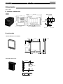
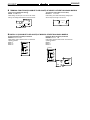
1
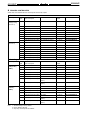
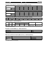
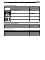
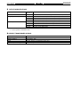
Digital Controller-Version II
ES100X/P
Intelligent Digital Controller and
Programmer
Programmed with easy-to-use support
software (ES Tools) or use front panel
Use fuzzy fine-tuning to easily
accomplish precise adjustment of PID
parameters
Programmable front panel function keys
and five levels of security enhance
operator interface without compromising
system integrity
A hybrid control function (advanced PID
and fuzzy logic) is incorporated for
high-precision control
A single controller performs cascade,
feed forward, ratio, valve control,
heat/cool control (ES100 Models with
secondary inputs are also available)
A maximum of 400 steps are possible
(99 program patterns, 99 steps)
Ordering Information
The Controller part number does not include an output module. Order one or two Output Module(s) separately for each Controller.
MODEL NUMBER LEGEND
Controllers
ES100X or P
1
2
3
4
1. P = Programmer/Heat Cool
X = Standard /Heat Cool
Note:
Two mechanical relays and heater
burnout are standard on all ES100’s
5
6
7
8
8. Product Inspection Sheet
K:
Yes
7. Digital I/O
B:
Digital inputs only (3 points on back of unit)
D:
Digital I/O (3 input points and 2 output points)
E:
Optional external digital I/O or BCD (8 input points
and output points respectively)
6. Transmission Output
F:
Yes (4 to 20 mA)
5. Communications
01: RS-232C
04: RS-422/RS-485
4. Heater Burnout Detection
H:
Yes
3. Secondary Analog Input
W:
Yes
2. Control Method and Outputs
AA: Standard, heating/cooling
RRP: Valve control (proportional
positioning)
ES100X/P
ES100X/P
PROCESS CONTROLLERS
All ES 100’s come standard with two control outputs and two relay outputs.
8-Bank Process Controller
Control System
Analog
Inputs
Digital on--board/external
inputs and outputs
Serial communications
Transfer
Output
Part number
Standard and
Heating/Cooling
(see note 1)
1
None
None
None
ES100X-AAH
1
3 inputs
None
4 to 20 mA
ES100X-AAHFB
1
8 external inputs and outputs
None
4 to 20 mA
ES100X-AAHFE
1
8 external inputs and outputs
RS--232C
4 to 20 mA
ES100X-AAH01FE
1
8 external inputs and outputs
RS--422/485 (see note 2)
4 to 20 mA
ES100X-AAH04FE
2
3 inputs
None
4 to 20 mA
ES100X-AAWHFB
2
8 external inputs and outputs
None
4 to 20 mA
ES100X-AAWHFE
2
8 external inputs and outputs
RS--232C
4 to 20 mA
ES100X-AAWH01FE
2
8 external inputs and outputs
RS--422/485 (see note 2)
4 to 20 mA
ES100X-AAWH04FE
1
3 inputs
None
4 to 20 mA
ES100X-RRPFB
1
8 external inputs and outputs
None
4 to 20 mA
ES100X-RRPFE
1
8 external inputs and outputs
RS--232C
4 to 20 mA
ES100X-RRP01FE
1
8 external inputs and outputs
RS--422/485 (see note 2)
4 to 20 mA
ES100X-RRP04FE
2
3 inputs
None
4 to 20 mA
ES100X-RRPWHFB
2
8 external inputs and outputs
None
4 to 20 mA
ES100X-RRPWHFE
2
8 external inputs and outputs
RS--232C
4 to 20 mA
ES100X-RRPWH01FE
2
8 external inputs and outputs
RS--422/485 (see note 2)
4 to 20 mA
ES100X-RRPWH04FE
Valve Positioning
(see note 3)
8-Bank Programmable Ramp/Soak Process Controller
Control System
Analog
Inputs
Digital on--board/external
inputs and outputs
Serial communications
Transfer
Output
Part number
Standard and
h ti /
heating/cooling
li
(note 1)
1
None
None
4 to 20 mA
ES100P-AAH
1
3 inputs, 2 outputs
None
4 to 20 mA
ES100P-AAHFD
1
8 external inputs and outputs
None
4 to 20 mA
ES100P-AAHFE
2
8 external inputs and outputs
None
4 to 20 mA
ES100P-AAWHFE
1
8 external inputs and outputs
RS--232C
4 to 20 mA
ES100P-AAH01FE
2
8 external inputs and outputs
RS--232C
4 to 20 mA
ES100P-AAWH01FE
1
8 external inputs and outputs
RS--422/485
(note 2)
4 to 20 mA
ES100P-AAH04FE
2
8 external inputs and outputs
RS--422/485
(note 2)
4 to 20 mA
ES100P-AAWH04FE
1
3 inputs, 2 outputs
None
4 to 20 mA
ES100P-RRPFD
1
8 external inputs and outputs
None
4 to 20 mA
ES100P-RRPFE
2
8 external inputs and outputs
None
4 to 20 mA
ES100P-RRPWFE
1
8 external inputs and outputs
RS--232C
4 to 20 mA
ES100P-RRP01FE
2
8 external inputs and outputs
RS--232C
4 to 20 mA
ES100P-RRPW01FE
1
8 external inputs and outputs
RS--422/485
(note 2)
4 to 20 mA
ES100P-RRP04FE
2
8 external inputs and outputs
RS--422/485
(note 2)
4 to 20 mA
ES100P-RRPW04FE
Valve
P iti i
Positioning
(note 3)
Note:
1. Standard setting is factory default.
2. Factory default is RS-422.
3. Only relay control outputs are available.
ES100X/P
ES100X/P
Temperature Inputs (Selections Available within the ES100X/P Controller)
Input type
y (switch
(
selectable))
Temperature
range
Thermocouples
Platinum RTD
Type R/S
Type K1
Type K2
Types J1/L1
Types J2/L2
Types JPt/Pt
°C
0 to 1,700
--200 to 1,300
0.0 to 600.0
--100 to 850
0.0 to 400.0
--199.9 to 600.0
°F
0 to 3,000
--300 to 2,300
0.0 to 999.9
--100 to 1,600
0.0 to 750.0
--199.9 to 999.9
Unit of measure
1°C or F, main setting and alarm
Input type
y (switch
(
selectable))
Thermocouples
Temperature
range
Types T/U
Type E
Type B
Type N
Type W
Type PLII
°C
--199.9 to 400
0 to 600
100 to 1,800
0 to 1,300
0 to 2,300
0 to 1,300
°F
--199.9 to 700
0 to 1,100
300 to 3,000
0 to 2,300
0 to 3,000
0 to 2,300
Unit of measure
1°C or F, main setting and alarm
Current/Voltage Inputs (Selections Available within the ES100X/P controller)
Input
Current
Range
4 to 20 mA
Voltage
0 to 20 mA
0 to 10 mV
0 to 100 mV
--10 to 10 mV
1 to 5 V
0 to 1 V
0 to 5 V
0 to 10 V
OUTPUT MODULE -- ORDER SEPARATELY
Output
Part
number
Relayy
output
t t
SSR
output
t t
Voltage output (for driving SSR)
12 VDC, NPN
24 VDC, NPN
24 VDC, PNP
E53-R
E53-S
E53-Q
E53-Q3
E53-Q4
Linear voltage
g output
Linear current output
E53-V34, 0-10 VDC,
E53-V35, 0-5 VDC
E53-C3, 4-20 mA
E53-C3D, 0-20 mA
Note: The E53-C cannot be used.
CURRENT TRANSFORMERS (CT) -- ORDER SEPARATELY
Hole diameter
Part number
5.8 mm (0.23 inch)
E54-CT1
12.0 mm (0.47 inch)
Note: The E54-CT2 cannot be used.
E54-CT3
ES TOOLS SUPPORT SOFTWARE (IBM PC/AT PS/2) -- ORDER SEPARATELY
Part number
Item
ES100-YA904-EV2
Support Software
Cable for Support
S f
Software
25-pin
ES100-CT022-202
9-pin
ES100-CT023-202
Note: Cables for front jacks are sold separately.
ES100X/P
ES100X/P
CABLES -- ORDER SEPARATELY
Part Number
Description
Connecting
g cables
Relay output blocks
For one G7TC-OC08 output block and XW2B-20G4/5 input block
G79-200C-175-ES1
For G7TC-OC08 output block only
G79-200C-ES1
For XW2B-34G4/5 BCD input block only
XW2Z-200C
8 inputs, 12 VDC
G7TC-OC08-DC12
8 inputs, 24 VDC
G7TC-OC08-DC24
8 inputs, DC
XW2B-20G4/5
8 inputs, BCD
XW2B-34G4/5
AC OUTAC OUTAC OUTAC OUTAC OUTAC OUTAC OUT
+
_
0
1
2
3
4
5
6
7
C0
C1
C2
C3
C4
C5
C6
C7
Input terminal blocks
1 3 5 7 9 11 13 15 17 19
2 4 6 8 10 12 14 16 18 20
XW2B-20G4
ACCESSORIES -- ORDER SEPARATELY
Item
Part number
Watertight Cover NEMA 4X
Y92A-96N
Terminal Cover (conforms to VDE0106)
E53-COV01
ES100 DOCUMENTATION
Manual
Catalog number
ES100P Digital Controller User’s Manual
H69
ES100X Digital Controller User’s Manual
H70
ES100 Support Software ES/TOOLS Support Software User’s Manual
H71
ES100 Digital Controller User’s Manual (Communications Guide)
H72
ES100 Digital Road Map Programming Manual
H03OAA1
ES100X/P
ES100X/P
Specifications
RATINGS
Supply voltage
100 to 240 VAC, 50/60 Hz
Operating voltage range
85% to 110% of rated supply voltage
Power consumption
Approx. 20 VA (at 100 VAC) to 25 VA (at 240 VAC)
Analog
g input 1
( i iinput)
(main
t)
Analog
g input 2 (aux.
(
i
input,
t ES100X only)
l )
Current input
4 to 20 mA, 0 to 20 mA (impedance: 150Ω±10%)
Voltage input
1 to 5 V, 0 to 5 V, 0 to 1 V, 0 to 10 V, 0 to 10 mV, 0 to 100 mV, --10 to 10 mV (impedance: 1 MΩ
min.)
Thermocouple
R, S, K, J, T, E, B, N, L, U, PLII, W
Platinum
resistance
thermometer
Pt100, JPt100
Current input
4 to 20 mA (impedance: 150Ω±10%)
Voltage input
1 to 5 V (impedance: approx. 1 MΩ)
CT input (see note 1)
Connect the dedicated CT (E54-CT1 or E54-CT3).
Potentiometer input (see note 1)
100 Ω to 2.5 kΩ
Control output
(see note 2)
Output Unit (sold separately) (use the Output Unit to obtain a control output. The position
proportional output type, however, has Relay Output Units only.)
Control mode
On board digital
g
output
t t
Hybrid of fuzzy logic and advanced PID control with auto-tuning and fine-tuning or ON/OFF.
Relay output
Two Independent outputs (SPDT and SPST-NO), 250 VAC, 3 A
Open collector
output
Common outputs, 24 VDC+10%/ --15%, max. load current: 100 mA
1 output, 4 to 20 mA with a load of 600 Ω max.
Transmission output
External signal input
Power supply
24 VDC +10%/--15%,
(the model with expansion I/O needs an external power supply)
Current when the signal is ON: 3 mA max.
Leakage current when the signal is OFF: 0.3 mA max.
Setting method
Digital setting with Up and Down Keys or ES TOOLS Support Software (via RS-232C terminal
on the front panel or remotely through back terminals
Indication method
Digital indications (character height: PV: 14.2 mm, SV: 10.2 mm, BANK, STEP, PTN: 7.6 mm)
(color PV: red, SV: green, BANK, STEP, PTN: yellow)
Bar graph indication (resolution: 10; color: green)
Status of ramp and soak (displayed by three green LEDs (ES100P only)
Other functions
Manual output.
Communications: RS-232C, RS-422/RS-485, BCD.
Assignments: front keys, setting/display items, digital I/O, and analog I/O.
Processing: , , , , primary time-lag filters, linear approximation, broken line
approximation, extraction of a square root, Boolean operators, average addition, average
movement.
Four internal ON/OFF timers; four internal counters.
Heating/cool control (except the Proportional Positioning Model)
SP setting limiter, SP rise/fall rate limiter, MV (output) change rate limiter, multi-level key
protect selection etc.
8 bank: set value, event output, PID parameter MV, (output) limiter; program bank (ES100X
only); Cascade control (possible with a single model with secondary input);
Fixed SP; time signal; step output (ES100P only) 99 patterns with 400 steps.
Note: 1. Either a CT input or a potentiometer input is available (both of them cannot be used at the same time).
2. All control outputs are electrically insulated from the internal circuitry (except transfer output and auxiliary terminal output).
ES100X/P
ES100X/P
OUTPUT MODULE RATINGS
Relay Output Module
E53-R
(see note 1)
SPDT; 5 A, 250 VAC (resistive load)
SSR Output Module
E53-S
SPST-NO; 1 A, 75 to 250 VAC; leakage current: 1.5 mA max. (at 200 VAC)
Voltage Output Module (see note 2)
E53-Q
40 mA max., 12 VDC; NPN (with short-circuit protection)
E53-Q3
20 mA max., 24 VDC; NPN (with short-circuit protection)
E53-Q4
20 mA max., 24 VDC; PNP (with short-circuit protection)
E53-C3
4 to 20 mA, DC: 600 Ω max.; resolution: approx. 2,600
E53-C3D
0-to 20 mA, DC: 600 Ω max.; resolution: approx. 2,600
E53-V34
0-10 VDC, Linear voltage output
E53-V35
0-5 VDC, Linear voltage output
Linear Output Modules
Note: 1. If control period is less than 5 seconds, a solid state relay (E53-S) should be used instead of the E53-R.
2. For driving external G3PA/G3NA SSR
CURRENT TRANSFORMER RATINGS
Max. continuous heater current
50 A
Dielectric strength
1,000 VAC (for 1 min)
Vibration resistance
50 Hz (approx. 10G)
Weight
E54-CT1: Approx. 11.5 g; E54-CT3: Approx. 50 g
Accessories (E54-CT3 only)
Contact: 2; Plug: 2
ES100X/P
ES100X/P
CONTROLLER CHARACTERISTICS
Item
Indication accuracy (see
note)
ES100X
ES100P
Thermocouple
(±0.1% of indication value or ±1°C, whichever greater) ±1 digit max.
Platinum
resistance
thermometer
(±0.1% of indication value or ±0.5°C,
whichever greater) ±1 digit max.
Voltage/
current input
(±0.1% FS, ±1 digit max.)
Display range
--9999 to 9999 (limited by input type)
ON/OFF control hysteresis
0.01% to 99.99% FS (in units of 0.01%)
Proportional band
0.0% to 999.9% FS (ON/OFF control when 0.0%)
0.1% to 999.9% FS (proportional position model) (in units of 0.1%)
Integral (reset) time
0 to 9,999 s (PD control when 0 s) (in units of 1 s)
Derivative (rate) time
0 to 9,999 s (PI control when 0 s) (in units of 1 s)
Fuzzy intensity
0.0% to 100.0% (Advanced PID control (2-PID) when 0.0%) (in units of 0.1%)
Event set value
Equivalent to --200.0% to 200.0% FS of industrial value or unit
Control period
1 to 120 s (in units of 1 s)
Sampling period
0.1 s min. type 0.2 s (in units of 1 s)
Display refresh period
1x, 2x, 5x, or 10x sampling period
PV compensation
Equivalent to --100.0% to 100.0% FS of industrial value or unit
Manual manipulated value
Manipulated value limit
--5.0% to 105.0%
Lower limit
--5.0% to --0.1% max.
Upper limit
+0.1% min. to 105.0%
Setting time (1 step)
---
0 to 99 hours 59 minutes or 0 to 99
minutes 59 seconds
Program capacity
---
Total steps 400 max. (99 patterns, 99
steps)
Programming method
---
Break point method (patterns can be
decided by the user)
Insulation resistance
20 MΩ min.
Dielectric strength
Vibration resistance
Shock resistance
Ambient temperature
Ambient humidity
2,000 VAC, 50/60 Hz for 1 min between terminals of different polarities
Malfunction
10 to 150 Hz, 0.5-mm single amplitude each in X, Y, and Z directions
Mechanical
10 to 150 Hz, 0.75-mm single amplitude each in X, Y, and Z directions
Malfunction
20G max., 3 times each in 6 directions
Mechanical
30G max., 3 times each in 6 directions (20G’s in the forward direction)
Operating
--10° to 55°C (14° to 131°F) with no icing
Storage
--25° to 65°C (--13° to 149°F) with no icing
Operating
35% to 85%
Memory protection
Enclosure ratings
Lithium cell backup (10 years at normal room temperature)
Front panel
IEC standard IP50 (with water proof cover: IP66, NEMA4)
Rear case
IEC standard IP20
Terminals
IEC standard IP00 (with terminal cover: VDE 0106/P100)
Standards/Approvals
UL1092, CSA22.2 No. 14, CSA22.2 No.
1010-1
Weight
Approx. 800 g
Note: Indication accuracy varies with the type of sensor and the sensing temperature as follows:
K and T sensor (--100°C max.), R, S, and W sensor (200°C max.), and U sensor: ±2°C±1 digit; B sensor (400°C max.): ±6°C±1
digit indication accuracy without using the built-in cold contact compensation circuit is ±0.1% FS or ±1°C whichever is smaller except for the following sensors: R and S sensor (200°C max.): ±1.5±1 digit; L2 and U sensor: ±1°C±1 digit
ES100X/P
ES100X/P
OUTPUT MODULE CHARACTERISTICS
Relay unit life expectancy
Mechanical
10,000,000 operations min.
Electrical (max. load)
100,000 operations min.
HEATER BURNOUT DETECTION CHARACTERISTICS
Max. heater current
50 A, single-phase
Monitor accuracy of input current
±5% FS ±1 digit max.
Heater burnout detection setting range 0.0 to 50.0 A (see note 1)
Heater current monitor range
0.0 to 55.0 A
Min. detectable ON time
200 ms (see note 2)
Note: 1. Heater burnout is not detected when current is set to 0.0 A; the burnout alarm will be automatically turned ON when current is
set to 50.0 A.
2. When the control output is ON for less than 200 ms, heater burnout is not detected and heater current is not measured.
SUPPORT SOFTWARE CHARACTERISTICS (ES TOOLS)
Personal computer
IBM PC/AT, IBM PS/2
Display
EGA (VRAM 256 K-byte), VGA
Main memory
640 K-byte
Communications method
RS-232C; half-duplex
Transmission speed
9,600 bps
PC-DOS version
V3.20/V3.30/V4.00/V5.0
Printer
EPSON FX-80 series, HP Laser Jet IIP (PCL4 min.), HP Laser Jet IV
COMMUNICATIONS
Communications
RS-232C
RS-422
RS-485
BCD
Transmission output
Transmission method
None,
half-duplex
4-wire,
half-duplex
2-wire,
half-duplex
Data select code
method
4 to 20 mA
Load: 600 Ω max.
resolution: 12-bit
Synchronization method
Start-stop synchronization
---
Baud rate
1,200/2,400/4,800/9,600/19,200 bps
---
Transmission code
ASCII (7-bit) (see note 3)
---
Note: 1. The maximum total cable length must not exceed the following limits.
RS-422: 500 m, RS-232C: 15 m, RS-485: 500 m
2. A maximum of 32 Temperature Controllers can be connected to one host computer using serial communications (RS-422 or
RS-485).
3. 8-digit ASCII codes can be also used.
4. Front panel communications port at 9600 BPS, 8 data bits, even parity, two stop bits, accessible only with Omron 9/25 pin serial
cable.
ES100X/P
ES100X/P
Operation
SAMPLING PERIOD
The sampling period of the ES100-series Digital Temperature Controller is factory-set to 200 ms If only the advanced PID control is used, the
sampling period will vary with the Model as follows (with a baud rate of 9,600 bps for the Models incorporating a communications function):
Model
Sampling period
Model
Sampling period
ES100X-AAH
100 ms
ES100X-AAHFB
100 ms
ES100X-AAHFD
100 ms
ES100X-AAHFE
100 ms
ES100X-AAWHFB
100 ms
ES100X-AAWHFE
100 ms
ES100X-AAH01FE
100 ms
ES100X-AAH04FE
100 ms
ES100X-AAWH01FE
200 ms
ES100X-AAWH04FE
200 ms
ES100X-RRPFB
100 ms
ES100X-RRPFD
100 ms
ES100X-RRPFE
100 ms
ES100X-RRPWFB
100 ms
ES100X-RRPWFE
100 ms
ES100X-RRP01FE
100 ms
ES100X-RRP04FE
100 ms
ES100X-RRPW01FE
200 ms
ES100X-RRPW04FE
200 ms
ES100P-AAH
100 ms
ES100P-AAHFD
100 ms
ES100P-AAHFE
100 ms
ES100P-AAWHFE
200 ms
ES100P-AAH01FE
200 ms
ES100P-AAH04FE
200 ms
ES100P-AAWH01FE
200 ms
ES100P-AAWH04FE
200 ms
ES100P-RRPFD
200 ms
ES100P-RRPFE
200 ms
ES100P-RRPWFE
200 ms
ES100P-RRP01FE
200 ms
ES100P-RRP04FE
200 ms
ES100P-RRPW01FE
200 ms
ES100P-RRPW04FE
200 ms
Control Operation Period
The control operation period is an important factor for the following control operations:
• Heating/cooling control
• Cascade control
• Fuzzy control
• Analog I/O assignment
• Digital I/O assignment
• No. of events used
• No. of times that ON/OFF timer used
• Input type selector (linearization required or not)
• Terminal communications baud rate
• Use of digital I/O (BCD communication)
Note: Refer to ES100X/ES100P Operation Manual for details.
The control operation period can be checked with the monitor (character P229) in the check mode.
ES100X/P
ES100X/P
Dimensions
Unit: mm (inch)
PROCESS CONTROLLERS
ES100X
ES100P
13 (0.51)
112
(4.41)
Panel Cutouts
169 (6.65)
160 (6.30)*
96 (3.78)
91
(3.58)
110 (4.33) min.
120 (4.72) min.
92 (3.62)
*175 (6.89) with a terminal cover
92 (3.62)
When mounting more than one Unit
ACCESSORIES
Y92A-96N Watertight Cover-NEMA4X
20.5 (0.81)
10 (0.39)
131.8
(5.19)
92 (3.62)
2 (0.08)
92
(3.62)
125.3
(4.93)
115.6 (4.55)
28 (1.10)
E53-COV01 Terminal Cover
81.9 (3.22)
88.2 (3.47)
72.8 (2.87)
66.9 ((2.63)
23 (0.91)
ES100X/P
ES100X/P
Installation
FACTORY-SET TERMINAL CONFIGURATION
Basic Model ES100 -AAH
34
17
NOT USED
CT input
16
33
7
24
Power
supply
CT
32
15
6
+
5
AO1
(control output)
23
+
31
14
A02
22
--
13
30
4
-b
3
SUB1
(upper-limit a
alarm output) 2
EV1
c
1
35
25
8
21
SUB2
12
(upper-limit
alarm output)
EV2
11
20
Expansion
connector
AI1
analog
input 1
(K1)
29
28
19
The allocation shown in the diagrams is applicable to all
Basic Models.
Input K1: --200 to 1,300°C (--328 to 2372°F)
Control output: Heating control
Auxiliary output: Upper-limit deviation alarm (to be set
with EV1 and EV2)
If the heating/cooling control mode is selected, AO1 is
used for heating and AO2 is for cooling control output.
To use AO1 and AO2, purchase Output Units.
+
27
10
18
-- 26
9
TERMINAL FUNCTIONS (FIXED) OF MODELS OTHER THAN BASIC MODELS
Proportional Positioning Control
ES100 -RRP
Upper Link RS422/485
ES100 04
c
14
5
Open output
Relay output
Close output
Relay output
422RDB
/485+
17
32
422RDA
/485--
16
422SDB 25
w
13
4
33
422SDA 24
o
31
Upper Link RS-232C
ES100 01
SD
17
RD
16
SG
15
NOT USED 25
NOT USED 24
SG
15
ES100X/P
ES100X/P
TERMINAL FUNCTIONS (POSSIBLE TO RELOCATE) OF MODELS OTHER THAN BASIC MODELS
Input 2 (4 to 20 mA Remote Setting)
ES100 W
Transmission Output (AI1 Process Value)
ES100 F
Initial setting: Use an input of 4 to 20 mA for remote
setting. The setting will be effective in the SP mode.
Initial setting: The value measured by analog input 1
will be output in a range of 4 to 20 mA.
+
10
4 to 20 mA
AI2
--
NOT USED 19
4 to 20 mA
+
+
1 to 5 V 18
-A03
34
35
9
DIGITAL I/O (POSSIBLE TO RELOCATE) OF MODELS OTHER THAN BASIC MODELS
Digital Input (Bank selectable) for ES100X
ES100XB
Digital I/O (Bank selectable) for ES100X
ES100XD
Initial setting: Used to select a bank. The terminals
operate as follows:
DI1[BNK0]
BNK0: 20
23
BNK1: 21
BNK2: 22
DI2[BNK1]
Initial setting: Used to select a bank. The terminals
operate as follows:
BNK0: 20
BNK1: 21
BNK2: 22
22
DI1[BNK0]
DI3 [BNK2]
21
20
23
DI2[BNK1]
22
DI3 [BNK2]
21
SUB power supply
19
20
SUB3
10
SUB4
9
24 V IN
COM
18
ES100X/P
ES100X/P
External Digital I/O for ES100X
ES100XE
External Digital I/O for ES100P
ES100PE
--
Digital input power supply
Digital input power supply
1
2
3
4
DI1
[BNK0]
5
6
DI2
[BNK1]
DI3
[BNK2]
7
8
DI4
DI5
9
10
DI6
DI7
11
12
DI8
DI9
13
14
DI10
DI11
15
16
DI12
DI13
17
18
DI14
DI15
Auxiliary output power supply --
19
20
N. C
21
24 V
IN
+
24 V
IN
4
5
6
DI2
[RST]
DI3
[HOLD]
7
8
DI4
DI5
9
10
DI6
DI7
11
12
DI8
DI9
13
14
DI10
DI11
15
16
DI12
DI13
17
18
DI14
DI15
Auxiliary output power supply --
19
20
N. C
22
21
22
23
24
24 V
IN
23
24
SUBOUT3
25
26
SUBOUT4
25
26
SUBOUT5
27
28
SUBOUT6
SUBOUT5
27
28
SUBOUT6
SUBOUT7
29
30
SUBOUT8
SUBOUT7
29
30
SUBOUT8
SUBOUT9
31
32
SUBOUT10
SUBOUT9
31
32
SUBOUT10
34
N. C
N. C
33
34
N. C
N. C
33
+
Digital I/O (Operation Instruction and Time Signal)
for ES100P
ES100PD
Initial setting: The RUN, RST, and HOLD input are
used to operate the program. Time signals set by programs are output from the terminals.
23
22
DI3 [HOLD]
21
20
2
3
+
DI2[RST]
1
DI1
[RUN]
24 V
IN
DI1[RUN]
--
SUB3
(time
signal 1)
SUB4
(time
signal 2)
10
SUB
power
supply
19
24 V IN
COM
9
18
+
SUBOUT3
(time signal 1)
SUBOUT4
(time signal 2)
DI1 through DI8 are digital input terminals and SUBOUT3 through
SUBOUT10 are digital auxiliary output terminals, both sets of which
can be allocated as instructed by the user’s software. The terminals
without allocation prior to shipping can be freely allocated as required by the user.
DI9 through DI15 are special terminals for BCD communication.
ES100X/P
ES100X/P
OMRON ELECTRONICS, INC.
OMRON CANADA, INC.
One East Commerce Drive
Schaumburg, IL 60173
885 Milner Avenue
Scarborough, Ontario M1B 5V8
1-800-55-OMRON
416-286-6465
Cat. No. GCTC12
1/99
Specifications subject to change without notice.
Printed in U.S.A.