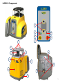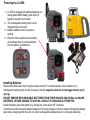
1
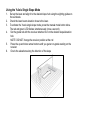
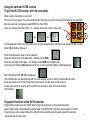
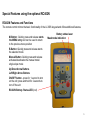
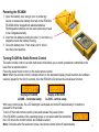
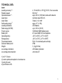
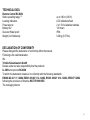
1
TABLE OF CONTENTS
Introduction
For Your Safety
Components
How to Use the Laser System
Powering the Laser
Turning On/Off the Laser
Laser Setup
Standard Features
Manual Mode
Y-Single Slope Mode
Mask mode
Activating/Deactivating Standby Mode
Operating Examples
Determining the Height of Instrument (HI)
Using the optional HL760 receiver
Pairing the HL760 receiver with the transmitter
2
Special Features using the optional RC402N
RC402N Features and Functions
Powering the RC402N
Turning On/Off the RC402N Radio Remote Control
Pairing the remote control with the transmitter
MENU Features at the RC402N
Setting Menu
Info
Service menu
Setting Menu Selections
HI-alert selection
Sensitivity
Language
CALIBRATION
Checking Calibration of the Y- and X-Axes
PROTECTING THE UNIT
CLEANING AND MAINTENANCE
PROTECTING THE ENVIRONMENT
WARRANTY
TECHNICAL DATA
3
Introduction
Thank you for choosing one of the Spectra Precision Lasers from the Trimble family of precision lasers.
The LL300S laser is an easy-to-use tool that offers accurate horizontal laser reference up to 1300 ft (400 m)
away using a receiver.
For Your Safety
For hazardless and safe operation, read all the user guide instructions.
- Use of this product by people other than those trained on this product may result in exposure to
hazardous laser light.
- Do not remove warning labels from the unit.
- The LL300S is a class 2 laser (<3,4mW) IEC 60825-1:2007)
- Never look into the laser beam or direct it to the eyes of other people.
- Always operate the unit in a way that prevents the beam from getting into people's eyes.
- If initial service is required, which results in the removal of the outer protective cover, removal
must only be performed by factory-trained personnel.
Caution: Use of other than the described user and calibration tools or other procedures
may result in exposure to hazardous laser light.
Caution: Using different than described at the LL300S user guide, may result in unsafe
operation.
4
LL300S - Components
f
e
b
d
a
c
i
h
g
m
j
o
l
o
n
n
k
5
Components
a Power Button
b Battery LED
c Manual/Standby Button
d Leveling LED
e HI/Manual LED
f Up and Down Arrow Buttons
g Rotor
h Sunshade
i Sighting Guides
j Axes-Alignment-Marks
k Recharge Jack
l Handle
m Battery door
n 5/8x 11 Tripod Mounts
o Rubber feet
How to Use the Laser System
Powering the Laser
Batteries
WARNING
Ni-MH batteries may contain small amounts of harmful substances.
Be sure to charge the battery before using it for the first time, and after not using it for an extended length of
time.
Charge only with specified chargers according to device manufacturer‘s instructions.
Do not open the battery, dispose of in fire or short circuit; it may ignite, explode, leak or get hot causing
personal injury.
Dispose in accordance with all applicable federal, state, and local regulations.
Keep the battery away from children. If swallowed, do not induce vomiting. Seek medical attention
immediately.
6
Powering the LL300S
1 – LL300S is shipped with alkaline batteries or a
rechargeable NiMH battery pack which is
keyed to prevent mis-insertion.
2 – The rechargeable battery pack can be
charged inside of the unit
3 – Alkaline batteries can be used as a
backup
4 – Plus and minus symbols at the battery
door indicate how to put the alkalines
into the battery compartment
Installing Batteries
Remove the battery door by turning the center screw 90° counterclockwise. Insert batteries (or a
rechargeable battery pack) into the housing so that the negative poles are on the bigger battery spiral
springs.
DO NOT REMOVE RECHARGEABLE BATTERIES FROM THEIR HOLDER AND INSTALL ALKALINE
BATTERIES, SEVERE DAMAGE TO UNIT WILL RESULT IF CHARGING IS ATTEMPTED.
Install the battery door and tighten it by turning the center screw 90° clockwise.
A mechanical switch prevents alkaline batteries from being charged. Only the original rechargeable battery
pack allows charging within the unit. Any other rechargeable batteries have to be charged externally.
7
Recharging the Batteries
Note: The battery LED shows the approximate charge of the batteries.
The LED will flash when battery voltage is between 3.8 and 4.0 volts.
The LED will be on continuously when battery voltage is less than 3.8 volts.
The charger requires approx. 13 hours to charge empty rechargeable batteries.
For charging, connect the plug of the charger to the recharge jack of the unit.
New or long-time out-of-use rechargeable batteries reach their best performance after being charged and
recharged five times. For Indoor applications the charger can be used as a power supply for the GL.
Alkaline batteries can be used as a backup. Insert 4 D-cell batteries noting the plus (+) and minus (-)
diagrams at the battery door.
The batteries should only be charged when the laser is between 50° F and 104° F (10°C
to 40°C). Charging at a higher temperature may damage the batteries. Charging at a
lower temperature may increase the charge time and decrease the charge capacity,
resulting in loss of performance and shortened life expectancy.
8
Laser Setup
Position the laser horizontally (tripod mount and rubber feet downward!) on a stable platform, wall mount or
tripod at the desired elevation.
The laser recognizes automatically whether it is used horizontally or vertically when switched on.
Note: When set up vertically, the unit switches always automatically into manual mode.
Turning On/Off the laser
Press the power button to turn On the laser.
The LEDs (b, d and e) are turned on for 3 seconds. Self-leveling will start at once. The unit is leveled when
the leveling LED (d) is no longer flashing (once every second). The rotor will not spin until the unit is
leveled. For the first five minutes after the laser self levels, the LED lights solid then flashes every four
seconds to let you know the laser is still level and the HI alert has been activated.
To turn Off the laser, press and hold the power button again.
If the laser is positioned beyond its self-leveling range of ±8%, the manual and leveling indicators flash
simultaneously and a warning sound is emitted. Reposition the laser within its self-leveling range.
Once leveled, the unit constantly monitors its level condition. The height change (HI) alert is activated 5
minutes after self-leveling was performed. The green LED (d) flashes every 4 seconds and HI appears at
the right corner of the optional remote control’s display.
Level errors > 30 mm/10 m put the unit into alert mode because they are generally caused by a disturbance
that could lead to inaccurate measurements. When entering into alert mode, the rotation stops, the laser
beam turns off, a warning sound is heard and the HI/MAN LED (e) flashes 2 x per second. Turn the unit off
and then on again. To ensure your former elevation, now you have to check or arrange the exact height.
9
Standard Features
Manual mode
In horizontal mode pressing the Manual button on the laser or remote control once changes the laser from
automatic self-leveling mode to Manual mode. Manual mode is indicated by the flashing (once every second)
red LED e.
In Manual mode (horizontal), the Y-axis can be sloped by pressing the Up- and Down-Arrow-buttons on the laser
or remote control. Additionally, the X-axis can be sloped by pressing the Left- and Right-Arrow-buttons on the
remote control.
To resume automatic self-leveling mode, press the manual button twice.
In vertical mode, the laser is always in MANUAL mode. Pressing the up and down arrow buttons adjust the
slope of the laser beam. The left and right arrow buttons at the remote control can be used to align the laser
beam to the right/left side.
To resume automatic self-leveling mode, press the manual button again.
Y-Single Slope Mode
The Manual button on the laser and remote control toggles the unit to Manual, the Y-axis Single Slope Mode,
then Automatic Mode. To activate the Y-axis single slope mode, press the Manual button at the laser or remote
control twice. This is indicated by the simultaneously flashing red e and green d LEDs (once every second).
In Y-axis single slope mode, the Y-axis can be sloped by pressing the Up- and Down-Arrow-buttons on the laser
or remote control, while the X-axis remains in automatic self leveling mode (e.g. when setting up sloped ceilings
or drive ways).
To resume automatic self-leveling mode from Y-axis single slope mode, press the manual button again.
10
Mask Mode
Mask Mode – allows you to electronically turn off the laser beam (electronic shutters) in up to 3 lighthouse
windows to prevent interference with other receivers on the jobsite. Mask Mode can be selected as a standard
feature as well as using the menu.
To activate the mask mode on the + or -Y-axis, press the up or down arrow button at the laser or remote control,
then within <1 second press and release the Manual button.
Press the right or left arrow button at the RC402N in sequence with the Manual button to activate/deactivate
the mask mode for the + or – X axis.
The RC402N display indicates which side of the laser the beam has been electronically turned off.
Note: The unit always powers up with the mask mode deactivated (default).
Activating/Deactivating Standby mode
Press and hold the Manual button at the laser or remote control for 3 seconds activates the Standby mode.
The self-leveling and rotation will be stopped and the beam will be turned off while the HI alert is still active.
The HI/MAN LED at the laser flashes red every 5 seconds while the RC402N display shows Standby.
To deactivate Standby mode and restore full operation of the laser, press and hold the
Manual button at the laser or remote control again for 3 seconds.
11
Determining the Height of Instrument (HI)
The height of instrument (HI) is the elevation of the laser’s beam.
The HI is determined by adding the grade-rod reading to a benchmark or known elevation.
Set up the laser and place the grade rod on a job-site benchmark (BM) or known elevation.
Slide the receiver up/down the grade rod until it shows an on-grade reading.
Add the grade-rod reading to the benchmark to determine the height of instrument.
Example:
Benchmark = 30.55 m (100.23 ft)
Rod reading = +1.32 m (+4.34 ft)
Height of instrument = 31.87 m (104.57 ft)
Use this HI as a reference for all other elevations.
Vertical Application
Level the tripod and allow the laser to level in automatic self-leveling mode.
Push the manual mode button and change the laser’s position on the tripod for vertical alignment by using
the vertical mounting thread.
Rotate the laser until the vertical laser plane aligns with the receiver’s on-grade position.
In order to avoid offset errors, the receiver should be used close to the elevation where the laser has been
set up.
If a remote control is available, the left and right arrow buttons can be used for fine adjustments.
Using the Y-Axis Single Slope Mode
1.
2.
3.
4.
5.
6.
Set up the laser and align it to the desired slope hub using the sighting guides on
the sunshade.
Check the laser beam elevation close to the laser.
To activate the Y-axis single slope mode, press the manual mode button twice.
The red and green LED flashes simultaneously (once a second).
Set the grade rod with the receiver attached to it on the desired slope/elevation
hub.
NOTE: DO NOT change the receiver position at the rod
Press the up and down arrow buttons until you get an on-grade reading on the
receiver
Check the elevations along the direction of the slope
Using the optional HL760 receiver
To pair the HL760 receiver with the transmitter
Make sure the transmitter is turned off.
First, turn on the receiver, then press and hold the Scroll up (A) and Scroll down (B) buttons for two seconds.
After two seconds, the display shows MENU first, then RDIO
Press and release the Enter button (C) – display shows the current radio mode.
or
or
A
B
C
If not already set to LS, press Units (C) button (current mode flashes) and then press Deadband (A) or Audio
button (B) until LS is displayed.
Press Units (C) button again to enter selection.
Press and release the Audio (A) button – display shows PAIR.
Press the Units (C) button again – the display shows PAIR and a rotating bar.
Then press and hold the Manual button and turn on the transmitter (Battery LED flashes fast).
After completing PAIR, OK will be displayed.
The LL300S pairs now automatically with the new receiver and turns back to the standard function.
Press and release the HL760 Power button two times to exit the menu at the receiver.
A laser symbol and an antenna is lit to confirm the receiver is ready for communication
with the laser.
Fingerprint function at the HL760 receiver
Fingerprinting makes sure the HL760 detects only the laser beam of the paired tarnsmitter.
Laser fingerprinting is automatically activated after a HL760/HL760U has been paired with the LL300S.
To recognize an ignore laser strikes from other than the paired transmitter takes typically 5 seconds;
sometimes few seconds more.
14
Special Features using the optional RC402N
RC402N Features and Functions
The remote control mirrors the basic functionality of the LL300S keypad and offers additional features.
M-Button : Quickly press and release starts
the MENU entry and can be used to return
to the previous menu position
E-Button: Quickly press and release starts
the selected mode
Manual Button: Quickly press and release
activates/deactivates the manual mode/
single slope mode
Up/Down Arrow Buttons
Left/Right Arrow Buttons
ON/OFF button - press for 1 second to turn
on the unit; press and hold for 2 seconds to
turn off the unit
RC402N Battery- Status-LED (red)
Battery status laser
Mask mode indication
15
Powering the RC402N
1. Open the battery door using a coin or similar pry
device to release the battery door tab on the RC402N.
RC402N will be shipped with alkaline batteries
Rechargeable batteries can be used optional but need
to be charged externally
2. Insert two AA batteries noting the plus (+) and minus (-)
diagrams inside the battery housing.
3. Close the battery door. Push down until it “clicks”
into the locked position.
Turning On/Off the Radio Remote Control
The radio remote control is a hand-held device that allows you to send operational commands to the
laser from a remote location.
Press the power button to turn on the radio remote control.
Note: When the remote control is initially turned on, the standard display (model number and software
version) appear for the first 3 seconds, then the RC402N LCD shows the actual laser function.
Display at RC402N
LL300S – horizontal setup
Display at RC402N
LL300S - vertical setup
With every button press, the LCD backlight is activated and turns off automatically if no button is
pressed for 8 seconds.
To turn off the radio remote control, press and release the power button.
If the RC402N is outside of the operating range or not paired with the transmitter,
the LCD shows the model number and software version.
Note: 5 minutes after the last button press, the remote control turns off automatically.
16
Pairing the remote control with the transmitter
First, make sure the transmitter and the remote control are turned off. Then press and hold the Manual
button and turn on the transmitter. During the next 4 seconds repeat the same steps on the remote control.
The Laser beeps and the remote’s display show Pairing OK for one second and then the same function
as the laser is actually working to indicate the transmitter has been matched with the
remote control.
RC402N Menu Functions
Press and release M button at the Standard Display to enter the MENU.
The actual available function will be marked in arrow brackets >> <<.
A down arrow at the the right site indicates that the user can scroll down through the menu using the down
arrow button.
After going to the next menu row, an up/down arrow at the the right site indicates that the user can scroll
up/down through the menu using the Up/Down arrows buttons.
Pressing and releasing button M changes the unit always back to the standard or previous display.
Press and release the Up/Down buttons until the desired function at the selected menu row is marked.
Press and release button E to open the submenu OR start the selected function.
Menu functions for the LL300S
Rotation
Press and release the M button at the Standard Display and select >>Rotation<<.
Press and release button E to display the actual rotation speed.
17
Mask mode
Press and release the M button at the Standard Display and select >>Mask Mode<<.
Depending on which side the beam should be turned off, the required side can
be selected. Press and release the E button, the mask symbol occurs.
For selecting the side, press and release one of the arrow button.
When all areas have been set, press button E to store the mask sector selection
until the unit will be turned off.
Note: The unit always powers up with the mask mode deactivated (default).
Setting Menu
Please see the Setting Menu details at the following pages.
Info
Press and release the M button at the Standard Display and select >>Info<<.
Up and Down Buttons can be used to toggle between About LS, Runtime and Radio
Press and release button E to confirm the selection.
The laser information (software version, serial number.), the runtime and the radio
channel of the laser will be displayed.
18
Service
Press and release the M button at the Standard Display and select >>Service<<.
Buttons Up/Down can be used to toggle between Calibration X and Calibration Y.
Press and release button E to confirm the selection.
The calibration at the selected axis starts the field calibration procedure.
Setting Menu
Press and release the M button at the Standard Display and select >>Settings<<.
Press and release button E to open the Setting Menu; select the desired function then press button E to open
the selected submenu function OR start the selected function.
HI-alert Selection
Select HI Alert and press and release button E to open the HI Alert submenu.
The desired HI-alert: 5 min.(Default), 30 seconds and HI-Off) can be selected using the Up/Down buttons.
Press and release button E to confirm the selected HI-alert.
19
Sensitivity Selection
Select >>Sensitivity<< and press and release button E to open the Sensitivity menu.
The desired Sensitivity: Low, Middle (Default) and High) can be selected using the Up/Down buttons.
Press and release button E to confirm the selected Sensitivity.
Select Language
Select >>Language<< and press and release button E to open the Language menu.
Use Up/Down buttons to select the required local language (EN, DE, IT, FR, ES, PT,
NL, DA, NO, SV, FI, PL, TR, CZ).
Press and release button E to store the selected Language; unit falls back to the standard menu.
20
Troubleshooting
Any error message at the RC402N can be deleted with a short press of button E. The table shows the
related description and possible solutions.
The next service center should be contacted if a different error message as shown at the table will be
displayed.
Error
codes
Description
Solution
21
Temporary EEprom problem
Press the E button to deletet the error message
120
HI alert - Unit Height changed
Check laser beam elevation
160
X or Y level sensor defect
Contact service center
21
CALIBRATION
Checking Calibration of the Y- and X-Axes
1. Set up the laser 30 m (100 ft) from a wall and allow it to level.
2. Set the grade to 0.000% in both axes.
3. Raise/lower the receiver until you get an on-grade reading for the
+Y axis. Using the on-grade marking notch as a reference, make
a mark on the wall.
Note: For increased precision, use the fine-sensitivity
setting (1.5 mm/ 1/16 in.) on the receiver.
4. Rotate the laser 180° (-Y axis toward the wall) and allow the laser
to re-level.
5. Raise/lower the receiver until you get an on-grade reading for the
–Y/axis. Using the on-grade marking notch as a reference, make
a mark on the wall.
6. Measure the difference between the two marks. If they differ
more than 3 mm at 30 m (1/8 inch at 100 feet), the laser needs
calibrating.
7. After checking the Y-axis, rotate the laser 90°. Repeat the above
starting with the + X axis facing the wall.
22
PROTECTING THE UNIT
Do not expose the unit to extreme temperatures or temperature changes (do not leave inside the car).
The unit is very robust and can resist damage if dropped even from tripod height. Before continuing your
work, always check the leveling accuracy. See Checking Calibration section.
The laser is water proof and can be used indoors and outdoors.
CLEANING AND MAINTENANCE
Dirt and water on the glass parts of laser or prism will influence beam quality and operating range
considerably.
Clean with cotton swabs.
Remove dirt on the housing with a lint-free, warm, wet and smooth cloth. Do not use harsh cleansers or
solvents.
Allow the unit to air dry after cleaning it.
PROTECTING THE ENVIRONMENT
The unit, accessories and packaging ought to be recycled.
This manual is made of non-chlorine recycling paper.
All plastic parts are marked for recycling according to material type.
Do not throw used batteries into the garbage, water or fire. Remove them in compliance
with environmental requirements.
Notice to Our European Union Customers
For product recycling instructions and more information, please go to:
www.trimble.com/environment/summary.html
Recycling in Europe: To recycle Trimble WEEE,
Call +31 497 53 2430, and ask for the “WEEE Associate”
Or
Mail a request for recycling instructions to:
Trimble Europe BV
c/o Menlo Worldwide Logistics
Meerheide 45
5521 DZ Eersel, NL
23
Warranty
Trimble warrants the LL300S to be free of defects in material and workmanship for a period of five years.
Trimble or its authorized service center will repair or replace, at its option, any defective part, or the entire
product, for which notice has been given during the warranty period. If required, travel and per diem
expenses to and from the place where repairs are made will be charged to the customer at the prevailing
rates. Customers should send the product to Trimble Navigation Ltd. or the nearest authorized service
center for warranty repairs or exchange, freight prepaid. Any evidence of negligent, abnormal use,
accident, or any attempt to repair the product by other than factory-authorized personnel using Trimble
certified or recommended parts, automatically voids the warranty. Special precautions have been taken to
ensure the calibration of the laser; however, calibration is not covered by this warranty. Maintenance of the
calibration is the responsibility of the user.
The foregoing states the entire liability of Trimble regarding the purchase and use of its equipment. Trimble
will not be held responsible for any consequential loss or damage of any kind. This warranty is in lieu of all
other warranties, except as set forth above, including any implied warranty merchantability of fitness for a
particular purpose, are hereby disclaimed. This warranty is in lieu of all other warranties, expressed or
implied.
24
TECHNICAL DATA
Laser
Leveling accuracy 1,3 :
Rotation speed:
Operational area 1,2 :
Laser type:
Laser class:
Self-leveling range 4 :
Leveling indicators:
Radio range (HL760):
Power source:
Battery life1 :
Operating temp.:
Storage temp.:
Tripod attachments:
Dust and Water proof:
Weight:
Low voltage indication:
Low voltage disconnection:
± 1.5 mm/30 m, 1/16“ @ 100 ft, 10 arc seconds
600 min-1
appr. 400 m (1300 feet) radius with detector
red diode laser 650 nm
Class 2, <3.2 mW
appr. ± 5° (+/-9%)
LED flashes
up to 100 m (330 ft)
10000mAh NiMH battery pack
47 hours NiMH; 60 hours alkaline
-20°C to 50°C (-4°F to 122°F)
-20°C to 70°C (-4°F to 158°F)
5/8 x 11 horizontally and vertically
IP66
3.1 kg (6.8 lbs)
LED battery indicator
unit shuts off
1) at 21° Celsius
2) under optimal atmospheric circumstances
3) along the axis
4) pre-tilt above 9%
25
TECHNICAL DATA
Remote Control RC402N
Radio operating range1,3 :
Leveling indicators:
Power source:
Battery life1 :
Dust and Water proof:
Weight (incl. Batteries):
up to 100 m (330 ft)
LCD indications flash
2 x 1.5V AA alkaline batteries
130 hours
IP66
0.26 kg (0.57 lbs)
DECLARATION OF CONFORMITY
Please disregard the declaration of conformity within the manual.
Following is the valid declaration:
We
Trimble Kaiserslautern GmbH
Declare under our sole responsibility that the products
LL300S and optional RC402N
To which this declaration relates is in conformity with the following standards:
EN300 440-2 V1.1.1:2004, EN301 489-03 V1.4.1:2002, EN301 489-01 V1.4.1:2002, EN50371:2002
following the provisions of directive R&TTE 1999/5/EC
The managing director
26
Electro-Magnetic Compatibility
Compliance statement (part 15.19) This device complies with part 15 of the FCC Rules. Operation is subject
to the following two conditions: (1) this device may not cause harmful interference, and (2) this device must
accept any interference received, including interference that may cause undesired operation. Warning (part
15.21) Changes or modifications not expressly approved by the party responsible for compliance could void
the user’s authority to operate the equipment. This in particular is applicable for the antenna which has been
delivered with the LL300S and RC402N Under Industry Canada regulations, this radio transmitter may only
operate using an antenna of a type and maximum (or lesser) gain approved for the transmitter by Industry
Canada. To reduce potential radio interference to other users, the antenna type and its gain should be so
chosen that the equivalent isotropically radiated power (e.i.r.p.) is not more than that necessary for succesful
communication.
27