1
Advanced
Communications Manual
for the
dataTaker Data Loggers
ROM Version 3.3
Copyright © 1993 dataTaker Pty Ltd
Document No. RM-003-A0
Contents
dataTaker
Table of Contents
Chapter 1 Introduction
About This Manual..................................................................
Who Should Use This Manual .................................................
1
1
Chapter 2 Communications Parameters and Protocols
Communication Parameters...................................................
Baud Rate.............................................................................
Data Bits, Stop Bits and Parity...........................................
Communications Protocols ....................................................
XON/XOFF Protocol............................................................
Proprietary DARTS Protocol..............................................
Network Protocol................................................................
Formats for Returning Data....................................................
Free Format Mode...............................................................
Fixed Format Mode.............................................................
Communication Echo..............................................................
Password..................................................................................
Defining a Password ...........................................................
Logging onto the Datataker.................................................
Entering Commands................................................................
Entering Commands in the Low Power Mode.....................
Entering Commands from the Host....................................
Entering Commands from the Memory Card.....................
Entering Commands from the Network.............................
General Rules for Entering Commands...................................
Command Line Editing.......................................................
Command Separators.........................................................
Self Documentation of Commands ....................................
3
3
3
3
4
4
5
5
5
5
6
6
7
7
7
8
9
9
9
9
10
10
11
Chapter 3 Special Serial Interface Commands
Alternative Commands for XON and XOFF ............................
Resetting the Datataker Receive Buffer...................................
Password..................................................................................
Defining a Password ...........................................................
Logging onto the Datataker.................................................
Determining if Logged On....................................................
Logging off from a Session..................................................
Enabling and Disabling the DARTS Protocol.........................
Enabling the DARTS Protocol............................................
Disabling the DARTS Protocol...........................................
The Delete Character ...............................................................
Copyright © 1993 dataTaker Pty Ltd
Document No. RM-003-A0
13
14
14
15
15
15
16
17
17
18
18
i
Contents
dataTaker
Table of Contents
Chapter 4 Free Format Mode for Returned Data
The Modes for Returning Data .................................................
Free Format Mode for Returning Data.....................................
Enabling the Return of Data.....................................................
Data Item Format.....................................................................
Modifying Numeric Format.....................................................
Floating Point Data Format................................................
Exponential Data Format ...................................................
Mixed Data Format..............................................................
Global Number of Significant Digits...................................
Number of Significant Digits and Decimal Places .............
Modifying the Data Item Format.............................................
Channel Number..................................................................
Channel Identifier...............................................................
Channel Names....................................................................
Units Text.............................................................................
Date or Day and Time Labels and Units..............................
Data Delimiter Character....................................................
Examples of Data Item Formats ..............................................
Data Block Format...................................................................
Data Block Format for Real Time Data...............................
Data Block Format for Stored Data ....................................
Examples of Data Block Formats........................................
Datataker Address....................................................................
Data Item Field Width ..............................................................
Date and Time Formats............................................................
Date and Day Number Formats...........................................
Time Formats ......................................................................
Decimal Day........................................................................
Date or Day and Time Labels and Units..............................
Automatic Return of Date and Time ........................................
Formatting Returns from STATUS .........................................
Formatting Returns from TEST...............................................
19
19
20
20
20
21
22
22
23
23
25
25
26
26
27
27
27
27
28
29
29
30
31
31
33
33
33
34
34
34
35
36
Chapter 5 Fixed Format Mode for Returned Data
The Modes for Returning Data .................................................
Fixed Format Mode for Returning Data...................................
The Benefits of Fixed Format Mode.........................................
Fixed Format Mode Message Structure....................................
Leader...................................................................................
Body......................................................................................
Terminator ..........................................................................
ii
39
39
40
42
42
43
44
Copyright © 1993 dataTaker Pty Ltd
Document No. RM-003-A0
Contents
dataTaker
Table of Contents
Fixed Format Mode Message Definition.................................
Alarm Messages ..................................................................
Program Change Messages..................................................
Returned Data Messages......................................................
Error Messages....................................................................
Information Messages ........................................................
Parameter Messages............................................................
Status Messages...................................................................
Test Messages ......................................................................
Password Query Messages...................................................
Suggested Models for use of Fixed Format Mode.....................
Programmed Model.............................................................
Query Model.........................................................................
44
44
44
45
46
46
46
47
52
53
53
53
54
Chapter 6 Datataker Asynchronous RS232 Transport System
DARTS Protocol.......................................................................
Enabling DARTS.................................................................
Disabling DARTS................................................................
Overview of DARTS.............................................................
Physical Aspects of the DARTS Protocol................................
DARTS Message Definitions ...................................................
Data Messages .....................................................................
Control Messages ................................................................
DARTS Message Sequencing ...................................................
Implementation of the DARTS Protocol by the Datataker ....
RS232 Services Module.......................................................
Transmitter Module............................................................
Receiver Module ..................................................................
Host Based DARTS Protocol Driver ........................................
Communications Fault Behaviour Analysis..........................
The CRC Algorithm..................................................................
55
55
56
56
57
57
58
58
59
61
61
62
63
64
65
68
Chapter 7 Using Modems - A Step by Step Guide
You Will Need ...........................................................................
Cabling.....................................................................................
Configuring the Remote Modem..............................................
Configuring the Datataker ......................................................
Configuring the Local Modem .................................................
Testing the Configuration .......................................................
A Final Word............................................................................
A Note about Passwords...........................................................
Copyright © 1993 dataTaker Pty Ltd
Document No. RM-003-A0
71
71
72
73
74
75
76
77
iii
Contents
dataTaker
Table of Contents
Chapter 8 Using Modems - A Complete Guide
RS232 Signal Definition and Requirements...........................
Cabling Between Computer and Local Modem.........................
Full Connection...................................................................
Minimum Connection.........................................................
The General Progress of a Call .................................................
Establishing a Call ..............................................................
Terminating a Call ..............................................................
Modem Settings and the Hayes AT Command Set...................
Getting Started..........................................................................
Essential Signals.................................................................
DTR Signal...........................................................................
DCD Signal...........................................................................
RI Signal...............................................................................
DSR Signal...........................................................................
RTS and CTS Signals...........................................................
Cable Summary ...................................................................
Other Issues..........................................................................
Procedure for Setting up the Modems for Testing...............
Testing the Modem Link......................................................
Applications Software.........................................................
Datataker, DeCipher Plus and Modems...................................
Cabling.................................................................................
Response Codes, Echo, Error Messages, etc.........................
Remote Modem Setup...........................................................
Remote Datataker Setup......................................................
Serial Communications Parameters .................................
Local Modem Setup..............................................................
How DeCipher Handles the Local Modem ...........................
How DeCipher Plus Handles the Local Modem ...................
Practical Experience, Hints and Troubleshooting .............
79
81
81
81
82
82
84
85
86
86
86
87
87
87
87
88
88
88
90
91
91
92
92
92
93
94
94
94
96
96
Appendix A The Hayes Command Set
The AT Commands...................................................................
The S-Registers.........................................................................
The Result Codes.......................................................................
Switch Settings.........................................................................
RS-232 Interpretations Worthy of Note...................................
A1
A5
A7
A8
A9
Appendix B Eavesdropping RS232 Communications
Eavesdrop Cable .......................................................................
DataScope.................................................................................
iv
B1
B2
Copyright © 1993 dataTaker Pty Ltd
Document No. RM-003-A0
dataTaker
Introduction
Chapter 1
Introduction
About
This Manual
This Advanced Communications Manual provides complete details
of the advanced features of data formatting and communication
protocol of the Datataker data loggers. This information is not
included the general purpose Datataker Users Manual supplied with
the loggers.
The Datataker models to which this manual applies are
• Datataker 50
• Datataker 500, 505, 515
• Datataker 600, 605, 615
with ROM Version 3.30 or later. Datatakers with earlier version
ROMs can be upgraded to the latest version ROM, to access these
advanced functions.
These Datataker models are identical in all respects in regard to
their communications.
The manual also provides details for using modems with the
Datataker data loggers, to communicate between remote loggers and
local computers.
Who Should
Use This Manual
Most users of the Datataker data loggers will not need to make use o f
the advanced features of data formatting and communication
protocol of the logger.
The standard data formatting functions and simple communication
protocol described in the Datataker Users Manual are adequate for
most applications. These are automatically selected whenever the
Datataker is powered up, or reset by the RESET command.
This manual is intended for use when the advanced features of data
formatting and communication protocol are required for special
purposes, such as
• developing host computer software for the Datataker which require
error detection and correction for all communications between the
logger and the computer
• developing host computer software for the Datataker which must
interrogate the Datataker to determine the current configuration o f
the logger, where the logger has been programmed either externally
to the package, or the logger has reprogrammed itself from alarms
• developing unique Datataker drivers for third party applications
software packages
Copyright © 1993 dataTaker Pty Ltd
Document No. RM-003-A0
1
Introduction
dataTaker
Notes
2
Copyright © 1993 dataTaker Pty Ltd
Document No. RM-003-A0
dataTaker
Communications Parameters and Protocols
Chapter 2
Communications Parameters and Protocols
All communications between the Datataker and the host computer
are in standard ASCII characters.
The Datataker is programmed using simple English-like commands
which are composed of standard ASCII characters.
These commands mostly consist of upper case characters. The
exception are the Switch Commands where lower case characters are
used to disable the switch function, and quoted text such as channel
names and alarm messages. Otherwise lower case characters are
ignored by the Datataker, and may be used to self document
commands.
All returned data is also composed of standard ASCII characters, and
as such can be imported into any spreadsheet, graphics, numerical
analysis, text editor or word processor package.
The Datataker has several protocols and commands which control
the behaviour of the logger as a communicating device.
Communication
Parameters
The RS232 COMMS serial interface of the Datataker has a user
selectable baud rate, and fixed parameters. There are no hardware
handshake lines supported.
Baud Rate
The communications baud rate for the RS232 COMMS serial
interface of the Datataker can be set by adjusting the internal DIP
switches, which are located behind the memory card socket.
The available baud rates are 300, 1200, 2400, 4800 and 9600
(Datataker 505/605 and Datataker 515/615 only) baud.
The baud rate DIP switches are read and used to initialise the serial
interface each time that the digital inputs are strobed (debounce
period). This ensures that the Datataker is always sensitive to
changes in baud rate.
Data Bits, Stop
Bits and Parity
The RS232 COMMS serial interface of the Datataker has the number
of data bits permanently set to 8, the number of stop bits
permanently set to 1, and the parity checking permanently disabled.
The serial interface of the host computer or terminal should be set to
the same settings.
Communications
Protocols
The Datataker supports the standard XON/XOFF communications
protocol to control the bi-directional flow of ASCII strings between
the logger and the host computer.
Copyright © 1993 dataTaker Pty Ltd
Document No. RM-003-A0
3
Communications Parameters and Protocols
dataTaker
The Datataker also has a proprietary communications protocol
based on a 16 bit CRC, which provides for error checking of both
received commands and transmitted data.
XON/XOFF
Protocol
The Datataker supports an XON/XOFF handshake protocol which
controls the transmission of data from the Datataker to a host
computer, and controls the receiving of commands and programs
from a host computer to the Datataker. The protocol prevents data
loss or corruption in the receiver due to communications overrun.
This XON/XOFF handshake protocol is permanently enabled in both
directions in the Datataker. Following initial power up, a hardware
reset, or a RESET command, the Datataker can receive commands
and transmit data immediately (XON true in both directions).
When transmitting data, the Datataker halts transmission within
two byte (or character) periods of an XOFF character being received
from the host, and resumes transmission when a subsequent XON
character is received. This allows the host computer to control the
transmission of data from the Datataker.
When receiving long programs comprising many commands, the
Datataker issues an XOFF character when the input buffer becomes
50%, 75% and 90% full, and then issues an XON character when the
input buffer is empty. This allows the Datataker to control
transmission of programs from the host computer .
The XOFF character is ASCII 19 (DC3), and can be sent directly from
the keyboard of a host running DeTerminal, DeCipher Plus or any
other communications software as Ctrl S.
The XON character is ASCII 17 (DC1), and can be sent directly from
the keyboard of a host running DeTerminal, DeCipher Plus or any
other communications software as Ctrl Q.
Note : If the Datataker is in the XOFF state when it drops to the low
power mode, then the XOFF state resumes when the Datataker later
powers up again.
Caution : If the host computer does not support the XON/XOFF
handshake protocol, then care should be taken that the Datataker
does not return data too quickly, and overrun the receive buffer o f
the host.
Proprietary DARTS The Datataker also has a proprietary 16 bit CRC communication
Protocol
protocol to protect against communications errors between the
logger and the host. These errors are manifested as data loss o r
corruption, which can be caused by electrical noise, temporary loss
of carrier in radio or satellite links, interference by telemetry
equipment, etc.
The Datataker DARTS protocol ensures that the command strings
received by the logger are the same as those sent by the host, and that
the data received by the host is the same as that sent by the
Datataker.
Use of the Datataker DARTS protocol requires that the host software
also supports the protocol. This in turn requires that the host
4
Copyright © 1993 dataTaker Pty Ltd
Document No. RM-003-A0
dataTaker
Communications Parameters and Protocols
software has been specifically written for the Datataker. The many
third party data acquisition packages that are available will not
support this protocol, unless a Datataker driver has been specifically
written.
DeCipher Plus supports the Datataker DARTS communications
protocol.
Following initial power up, a hardware reset, or a RESET command,
the Datataker DARTS communications protocol is disabled.
The Datataker DARTS communications protocol can be used in both
the Free Format Mode (see Chapter 4) and the Fixed Format Mode (see
Chapter 5), and is described in Chapter 6.
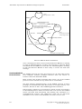
Network Protocol
The Datataker 500/600 series data loggers also implement a protocol
in the RS485 network between loggers. However this protocol is
always enabled, and is transparent to the user. There are no
commands for the network protocol.
Formats for
Returning Data
The Datataker has two format modes for returning data to the host
computer. The Format Mode is selected by the Data Format Switch
as follows
/H
Select Fixed Format Mode
/h
Select Free Format Mode (Default)
Following initial power up, a hardware reset, or a RESET command,
the Free Format Mode is selected.
Free
Format
Mode
The Datataker normally returns data and other system information
to the host computer or terminal in a Free Format Mode, which is a
descriptive or conversational style suitable for displaying directly
on a host screen and for printing.
In this mode the user can change the format of the returned data and
system information using a number of data formatting commands,
to suit particular requirements.
The Free Format Mode for returning data and system information is
described in detail in Chapter 4.
Fixed
Format
Mode
The Datataker also has an alternative format for returning data and
system information, which has been designed for optimally
transferring data to the host computer. This is the Fixed Format
Mode, which is a fixed data format which cannot be changed by the
user.
If the Free Format Mode is used to interface with host software, then
provision must be made in the host software to ensure that changes
in the data format do not confuse the software.
Copyright © 1993 dataTaker Pty Ltd
Document No. RM-003-A0
5
Communications Parameters and Protocols
dataTaker
However the Fixed Format Mode provides the host software with a
predictable Datataker environment in which to operate. In Fixed
Format Mode the Datataker provides
• a fixed format for data and system information, which has special
identifiers for each type of message, and date and time details
• a description of the scan schedules, channel details, alarms, etc.
which have been programmed into the logger
Use of Fixed Format Mode requires that the host software supports
the predefined data formats which this mode ensures. This requires
that host software has been specifically written for the Datataker.
The various third party data acquisition packages which are
available will not support this mode, unless a Datataker driver has
been specifically written.
The DeCipher Plus software supports the Fixed Format Mode.
When Fixed Format Mode is selected, current settings of the Channel
Number Switch (/N/n), the Channel Identifier Switch (/C/c), the
Units Text Switch (/U/u), the Echo Switch (/E/e), the Return Switch
(/R/r), Parameter22, Parameter24 and Parameter38 are saved.
These settings are restored when the Fixed Format Mode is exited
and the Free Format Mode resumed.
The Fixed Format Mode for returning data and system information
is described in Chapter 5.
Communication
Echo
During transmission of commands to the Datataker, transmitted
characters may optionally be echoed back to the host device.
Character echoing is only available if the Free Format Mode (/h) is
selected.
While character echoing is intended for use when the Datataker is
being supervised from a terminal, it may be used by a computer to
check if characters transmitted to the logger are correctly received.
Echo is enabled by the Echo Switch as follows
/E
Enable command echo (Default)
/e
Disable command echo
The Echo Switch defaults to /E when the Datataker is initially
powered up, is hardware reset or executes a RESET command.
Password
The Datataker has optional password protection for the RS232
COMMS serial interface. When the password is enabled,
communications through the RS232 COMMS serial interface is only
possible after the defined password has been entered.
Password protection prevents unauthorised access to the Datataker.
Password protection is also useful when the Datataker is connected
to a modem. This eliminates the possibility of line noise being
interpreted as commands during call establishment.
6
Copyright © 1993 dataTaker Pty Ltd
Document No. RM-003-A0
dataTaker
Communications Parameters and Protocols
Defining a
Password
The optional password is defined by the command in the general
format
PASSWORD="password "
where password is a text string of up to 10 case sensitive characters.
Defining the password as null removes an existing password.
The following command defines the password for the logger
PASSWORD="SecretCode"
Logging onto
the Datataker
After a password has been defined to the Datataker, then to later reestablish communications with the Datataker simply enter the
defined password
SecretCode
If the entered password matches the password stored in the
Datataker, then the Datataker responds with
Accepted
and signs the user on for a new session.
If the entered password does not match the stored password, then the
Datataker does not respond,
The RS232 COMMS serial interface remains open while there is
communications activity, or until the SIGNOFF command is issued.
If there is no communications activity for 300 seconds (5 minutes),
then the RS232 COMMS interface will automatically signoff. The
automatic signoff delay can be defined by the Parameter14
Command in the range of 1 - 255 seconds.
If the Datataker is issued a RESET command during a session, then
any stored password is lost.
The Datataker will respond to the DEL character with << regardless
of the password state. This allows a Datataker to be identified.
Entering
Commands
Programming commands are entered into the Datataker by any o f
four basic methods
• the most common method is to enter commands into the Datataker
directly from the host computer, via the RS232 COMMS serial
interface
Copyright © 1993 dataTaker Pty Ltd
Document No. RM-003-A0
7
Communications Parameters and Protocols
dataTaker
• commands can be recorded into a memory card, and automatically
read into the Datataker when the memory card is inserted into the
memory card socket
• commands can be entered into the Datataker 500/600 series loggers
via the NETWORK serial interface. The commands are transmitted
via the Datataker 500/600 network from a host computer, which is
connected to another logger in the network.
Note : The Datataker 50 does not support networking, and cannot
be commanded by this method.
• commands may be entered internally from alarms as a result of
alarm conditions becoming true
The command buffer within the Datataker will accept up to 250
characters. This limits single commands to a maximum length o f
250 characters.
Entering
Commands in the
Low Power Mode
The Datataker generally operates in the low power mode, waiting for
the next scan to become due or for commands to be received into the
RS232 COMMS serial interface.
When the Datataker is in the low power mode, various sections of the
logger, including the microprocessor and serial interface circuitry,
are powered off. Whenever a scan becomes due, or if command
characters are received into the RS232 COMMS serial interface, the
Datataker 'wakes up' to the normal power mode and performs the
necessary functions.
However if commands are sent to the Datataker while in low power
mode, then a number of the leading characters of the command w i l l
be missed as the logger wakes up.
The Datataker takes approximately 250 mS to wake, and so any
characters received during this period will be missed. The number o f
characters missed depends on the communications baud rate, such
that at higher baud rates the entire command may be missed.
This character loss is less of a problem when the Datataker is being
commanded manually from a terminal host, where typing speed
determines character rate. Generally only the first character will be
missed.
Loss of characters during the wake delay can be overcome by sending
several carriage return or line feed characters to wake the Datataker,
before entering command characters.
DeTerminal and DeCipher Plus provide for this wake up delay by
sending a linefeed character to the Datataker, and waiting 250 m S
before sending the command. A similar practice should be adopted
for all host software used to supervise the Datataker.
Missed characters will result in command syntax errors due to
incomplete commands being received. The Datataker will return
command error messages for what would appear to be syntactically
correct commands.
8
Copyright © 1993 dataTaker Pty Ltd
Document No. RM-003-A0
dataTaker
Communications Parameters and Protocols
Whenever the Datataker wakes from low power mode by characters
received into the RS232 COMMS serial interface, the logger remains
in the normal power mode for 30 seconds after the last character is
received, before dropping to the low power mode again.
In applications where low power mode is not required, such as when
an adequate power supply is available, then the automatic low power
mode can be disabled by the Parameter15=2 command. This
command can also be used to keep the logger awake during a
programming session, and the logger then returned to the automatic
low power mode by the Parameter15=0 command after the session.
The automatic low power mode is disabled whenever the Datataker is
powered from external power supplies.
Entering
Commands
from the Host
The most common method used to send commands to the Datataker
is to enter the commands directly from a host computer or terminal
connected to the RS232 COMMS serial interface.
Commands are either entered manually from the keyboard of a
terminal, a computer running DeTerminal, DeCipher Plus or a
communications or terminal emulation program, or directly from
special purpose software running in a computer.
Entering
Commands from
the Memory Card
The memory card has an area of memory reserved for storage o f
Datataker commands. This is referred to as the program area, and
can contain commands totalling up to 4090 characters.
Whenever a memory card is inserted into the memory card socket o f
the Datataker, the logger checks if there are any commands stored i n
the program area of the card and reads these into the command
buffer for execution.
Entering
Commands
from the Network
Commands can be entered into any of the Datataker 500/600 series
loggers within a Datataker local area network, via the network.
The host computer is connected to the RS232 COMMS serial
interface of any Datataker 500/600 series logger within the network.
Commands intended for any other Datataker 500/600 series logger
within the network are sent out of the NETWORK serial interface o f
host logger, and received into the NETWORK interface of the target
logger.
The direction of commands to different Datataker 500/600 series
loggers within the network requires that commands be prefixed by
an address, which matches the address of the target logger.
General Rules
for Entering
Commands
There are a number general rules for entering commands into the
Datataker, which apply to all methods of command entry.
These rules provide for simplicity and flexibility when entering
commands, while providing a syntax which is easy to use.
Copyright © 1993 dataTaker Pty Ltd
Document No. RM-003-A0
9
Communications Parameters and Protocols
Command
Line Editing
dataTaker
The Datataker supports several interactive line editing functions
during entry of commands.
The line editing functions particularly apply to the situation where
the Datataker is being supervised either from a terminal, or from a
computer running DeTerminal, DeCipher Plus, or any general
purpose communications or terminal emulation program.
The line editing functions are described in the sections below.
Backspace [BS]
A backspace character (ASCII 8) will cause the last character
transmitted by the host to be erased from the internal command
buffer of the Datataker.
If communications echo is enabled by the Echo Switch /E, then the
Datataker responds with a 'backspace space backspace' character
sequence, which has the effect of deleting the last character from the
command line on the terminal screen.
Repeated backspaces will erase successive characters from
command line, and will eventually erase the entire command.
Delete [DEL]
the
A delete character (ASCII 127) causes a partially or wholly entered
command to be aborted. The delete character must be sent before the
carriage return which terminates the command.
The Datataker responds with the characters << which indicates on a
terminal screen that the command has been aborted.
The Datataker will respond to the DEL character with << regardless
of whether Echo is disabled (/e) or of the password state. This allows
a Datataker to be identified.
Carriage Return
[CR]
Terminates a command line, and instructs the Datataker to process
the command and execute the commanded functions.
If communications echo is enabled by the Echo Switch /E then the
Datataker responds with a CR/LF sequence to the host.
Line Feed [LF]
The line feed character (ASCII 10) is ignored.
Tab and Space
Characters
The Tab and Space characters (ASCII 9 and ASCII 32) can both be
used to insert a space character. The Tab or Space character is the
delimiter character between the elements of a complete command.
If communications echo is enabled by the Echo Switch /E, then the
Tab and Space characters are echoed as a space character.
Command
Separators
10
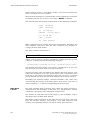
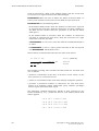
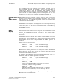
Space or tab characters are used within the command lines as
separators of the command components, as follows
Copyright © 1993 dataTaker Pty Ltd
Document No. RM-003-A0
dataTaker
Communications Parameters and Protocols
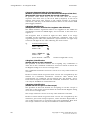
• there must be at least one separator between the command address,
command type and individual channels in a channel list as follows
#1
R10M
1..10V
^
^
1..2DSO=0
STATUS3
^
3..4DS
^
TEST
^
^
Omission of separators from between command components as
indicated will cause the remainder of the command to be aborted.
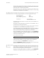
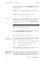
• separators are not permitted within the command address, the
command type, or individual channels in a channel list as follows
#
1
R
^
A
^
STATUS
10
^
M
^
1
..
^
10
^
V
^
1 ..2 DS0 = 0
^
^
^ ^
3
^
Inclusion of separators within the command components as
indicated will cause the remainder of the command to be aborted.
• only spaces or tabs may be used as separators.
Self
Documentation
of Commands
With the exception of the Switch Commands and quoted text, a l l
Datataker command characters and channel identifier characters
are strictly upper case characters (capitals).
Commands may be made self documenting by completing the name
for each command or identifier in lower case as follows
Repeat10Min Day Time 1..5Volt /Retn to host
When the command is read by the Datataker, all of the lower case
characters are ignored and only the upper case characters are
retained in the command. Therefore lower case characters do not
consume space in the internal command buffer.
Therefore the above command example would reduce to
R10M D T 1..5V /R
in the internal command buffer.
Self documentation of commands can be further improved by using
the underscore character to separate word combinations
Repeat_10_Min Day Time 1..6Thermocouple_T
Copyright © 1993 dataTaker Pty Ltd
Document No. RM-003-A0
11
Communications Parameters and Protocols
dataTaker
Self documentation may also be used in the Switch Commands.
However the case of the first command character following the /
must be maintained appropriate to the setting required (upper case to
enable the switch, and lower case to disable the switch) as follows
/Return_data /messages_off /echo_off
/return_no_data /Messages_on /Echo_on
12
Copyright © 1993 dataTaker Pty Ltd
Document No. RM-003-A0
dataTaker
Special Serial Interface Commands
Chapter 3
Special Serial Interface Commands
The Datataker data loggers have several special purpose commands
to manage the serial interface of the logger, and to manage the flow o f
communications via the RS232 COMMS port of the logger.
These special purpose commands are usually only used in advanced
applications, or to overcome problems encountered particularly
with telemetry systems.
All special purpose commands are processed in a different way to
normal Datataker commands, as follows
• The special purpose commands are processed immediately they are
received, regardless of the current workload of the Datataker
• The special purpose commands are processed outside of the normal
input command buffer in the Datataker, allowing them to operate
even when there are RS232 communications problems with the
logger
• The special purpose commands are processed outside of any other
RS232 command processing (such as the Datataker Asynchronous
RS232 Transport System - DARTS)
• Any messages generated by the special purpose commands bypasses
the normal RS232 output buffer, and is returned immediately
regardless of data, etc. currently being returned from the logger
Note : Unlike normal commands, these special purpose commands
do not need a terminating [CR/LF] sequence when sent to the
Datataker. The commands are executed immediately after the last
character of the command is received by the Datataker.
Alternative
Commands for
XON and XOFF
In some telemetry systems, telemetry equipment such as cellular
telephone modems, radio modems, satellite terminals, etc. may
intercept XON and XOFF characters and treat these as being for local
control. Therefore XON and XOFF characters sent by the host to the
Datataker to control the flow of data from the logger are not received
by the logger.
To overcome this potential problem, the Datataker also supports
alternative forms of the XON and XOFF commands as follows
^ZQXON
which is equivalent to XON
^ZSXOFF
which is equivalent to XOFF
Copyright © 1993 dataTaker Pty Ltd
Document No. RM-003-A0
13
Special Serial Interface Commands
dataTaker
Note : The ^Z indicates the Control Z character which must be sent to
the Datataker as ASCII 26, and not literally as circumflex Z.
These commands can be sent to the Datataker from DeTerminal and
DeCipher Plus using the interactive command as follows
\026QXON
\026SXOFF
where \026 is translated to a Control Z character when the command
is transmitted.
When these commands are transmitted by the host, they are passed
by the telemetry equipment as text strings to the Datataker, which
interprets them as XON and XOFF respectively.
Resetting the
Datataker
Receive Buffer
Occasionally telemetry equipment may interfere with XON/XOFF
flow control to the degree that the Datataker input and/or output
buffers become blocked.
This condition can be cleared by the communications buffers reset
command as follows
^ZCMSRST
which resets and clears the transmit and receive buffers, and sets the
XON/XOFF protocol to XON.
Note : The ^Z indicates the Control Z character which must be sent to
the Datataker as ASCII 26, and not literally as circumflex Z.
This command can be sent to the Datataker from DeTerminal and
DeCipher Plus using the interactive command as follows
\026CMSRST
where \026 is translated to a Control Z character when the command
is transmitted.
The Datataker responds to this command with the message
RS232 Reset
Caution : Use of this command will cause the current contents of the
transmit and receive buffers to be lost. However the program in the
Datataker, and any data stored in the memory, are unaffected.
Password
14
The Datataker has optional password protection for the RS232
COMMS serial interface. When the password is enabled,
communications through the RS232 COMMS serial interface is only
possible after the defined password has been entered.
Copyright © 1993 dataTaker Pty Ltd
Document No. RM-003-A0
dataTaker
Special Serial Interface Commands
Password protection prevents unauthorised access to the Datataker.
Password protection is also useful when the Datataker is connected
to a modem. This eliminates the possibility of line noise being
interpreted as commands during call establishment.
Defining a
Password
The optional password is defined by the command in the general
format
PASSWORD="password "
where password is a text string of up to 10 case sensitive characters.
Defining the password as null removes an existing password.
The following command defines the password for the logger
PASSWORD="SecretCode"
Logging onto
the Datataker
After a password has been defined to the Datataker, then to later reestablish communications with the Datataker simply enter the
defined password
SecretCode
If the entered password matches the password stored in the
Datataker, then the Datataker responds with
Accepted
and signs the user on for a new session.
If the entered password does not match the stored password, then the
Datataker does not respond.
The RS232 COMMS serial interface remains open while there is
communications activity, or until the SIGNOFF command is issued.
If there is no communications activity for 300 seconds (5 minutes),
then the RS232 COMMS interface will automatically signoff. The
automatic signoff delay can be defined by the Parameter14
Command in the range of 1 - 255 seconds.
If the Datataker is issued a RESET command during a session, then
any stored password is lost.
The Datataker will respond to the DEL character with << regardless
of the password state. This allows a Datataker to be identified.
Determining
if Logged On
Sometimes there may be uncertainty as to whether the Datataker
has a password defined, or during a session there may be uncertainty
as to whether you are still logged on to the Datataker.
Copyright © 1993 dataTaker Pty Ltd
Document No. RM-003-A0
15
Special Serial Interface Commands
dataTaker
The command
^ZLOGGEDIN
can be used to determine the current password state. This command
can be entered even if there is a password defined, but the user has
not logged on to the Datataker.
Note : The ^Z indicates the Control Z character which must be sent to
the Datataker as ASCII 26, and not literally as circumflex Z.
This command can be sent to the Datataker from DeTerminal and
DeCipher Plus using the interactive command as follows
\026LOGGEDIN
where \026 is translated to a Control Z character when the command
is transmitted.
If the Datataker responds to this command with the message
YES
this indicates that the user has already logged onto the Datataker
and a session is currently in progress, or indicates that no password
has been defined for the logger so a session is always in progress.
If the Datataker responds to this command with the message
NO
this indicates that there is a password defined, and the user has not
logged onto the Datataker.
Logging off
from a Session
In version 2.00 ROMs the method for ending a password protected
session was to use the SIGNOFF command.
In version 3.00 ROMs and later, the preferred method for ending a
password protected session is by using the command
^ZENDSESSION
Note : The ^Z indicates the Control Z character which must be sent to
the Datataker as ASCII 26, and not literally as circumflex Z.
This command can be sent to the Datataker from DeTerminal and
DeCipher Plus using the interactive command as follows
\026ENDSESSION
where \026 is translated to a Control Z character when the command
is transmitted.
16
Copyright © 1993 dataTaker Pty Ltd
Document No. RM-003-A0
dataTaker
Special Serial Interface Commands
If the Datataker responds to this command with the message
End of Session
this indicates that the user has completed the session and is logged
off the Datataker.
If the Datataker responds to this command with the message
NO PASSWORD
this indicates that there is no password defined, and so by default the
user remains logged on to the Datataker.
The SIGNOFF command is still available in version 3.00 ROMs and
later, for downward compatibility.
Enabling and
Disabling the
DARTS Protocol
The Datataker has a 16 bit CRC communication protocol to protect
against communications errors between the logger and the host.
The Datataker DARTS protocol ensures that commands received by
the logger are the same as those sent by the host, and that data
received by the host is the same as that sent by the Datataker.
Use of the Datataker DARTS protocol requires that the host software
also supports the protocol. This in turn requires that the host
software has been specifically written for the Datataker. The many
third party data acquisition packages that are available will not
support this protocol, unless a Datataker driver has been specifically
written.
DeCipher Plus supports the Datataker DARTS communications
protocol.
The operation of the Datataker DARTS communications protocol is
fully described in Chapter 6.
There are two special commands which control the activity of the
Datataker DARTS communications protocol.
Enabling the
DARTS Protocol
The Datataker DARTS communications protocol is enabled by the
command
^Z1PMODE=ONE
Note : The ^Z indicates the Control Z character which must be sent to
the Datataker as ASCII 26, and not literally as circumflex Z.
This command can be sent to the Datataker from DeTerminal and
DeCipher Plus using the interactive command as follows
\0261PMODE=ONE
where \026 is translated to a Control Z character when the command
is transmitted.
Copyright © 1993 dataTaker Pty Ltd
Document No. RM-003-A0
17
Special Serial Interface Commands
dataTaker
The Datataker responds to this command with
ENABLED
All commands issued after this special command must obey the
DARTS protocol to be accepted by the Datataker. All output from the
Datataker following the this command will obey the protocol.
Disabling the
DARTS Protocol
The Datataker DARTS communications protocol is disabled by the
command
^Z0PMODE=ZERO
The leading character after ^Z is numeric 0 (zero), and not the literal
character uppercase O.
Note : The ^Z indicates the Control Z character which must be sent to
the Datataker as ASCII 26, and not literally as circumflex Z.
This command can be sent to the Datataker from DeTerminal and
DeCipher Plus using the interactive command as follows
\0260PMODE=ZERO
where \026 is translated to a Control Z character when the command
is transmitted.
The Datataker responds to this command with
DISABLED
All commands issued after this special command must no longer
obey the protocol. All output from the Datataker following this
command will be as ASCII text strings.
The Delete
Character
A delete character (ASCII 127) causes a partially or wholly entered
command to be aborted. The delete character must be sent before the
carriage return which terminates the command.
The Datataker responds with the characters << which indicates on a
terminal screen that the command has been aborted.
The Datataker will respond to the DEL character with << regardless
of whether Echo is disabled (/e) or of the password state. This allows
a Datataker to be identified.
Because the DEL character will always be responded to by the
Datataker, this character can be used as a mechanism for Datataker
identification, and as a mechanism for automatic baud rate
detection by host software of the Datataker.
18
Copyright © 1993 dataTaker Pty Ltd
Document No. RM-003-A0
dataTaker
Free Format Mode for Returned Data
Chapter 4
Free Format Mode for Returned Data
The Modes for
Returning Data
The Datataker normally returns data to the host computer in the
Free Format Mode. This is a descriptive or conversational style,
which is suitable for displaying data directly on a host screen, for
printing data, and for passing data to purpose written and third
party data acquisition software packages.
The Free Format Mode has a default format for returned data, which
the user can change to suit particular applications by using a variety
of data formatting commands.
The Datataker also has an alternative mode for returned data, which
is specifically designed for transferring data to purpose written and
third party data acquisition packages. This is the Fixed Format
Mode, which is a fixed data format that cannot be changed by the
user.
The Fixed Format Mode for returning data and system information
is described in Chapter 5.
The format mode for returned data is selected by the Data Format
Switch as follows
/H
Select Fixed Format Mode
/h
Select Free Format Mode (Default)
Following initial power up, a hardware reset, or a RESET command,
the Free Format Mode is selected.
The Free Format Mode for returned data is described in this chapter,
including commands for defining the data format.
Free Format Mode In the Free Format Mode, all data is returned from the Datataker i n
for Returning Data user definable data item and data block formats. The formats apply
both to data returned directly to the host as the input channels are
scanned, and to stored data returned from the internal data memory
or memory card.
The data is returned in ASCII strings as either floating point data o r
exponential data, with channel identification and units text.
In these formats, each digit is an ASCII character (eg. 123.45), which
allows the returned data to be displayed directly onto a terminal
screen for viewing, to be input into a computer for processing, or to be
sent directly to a serial printer to produce hardcopy.
When the returned data is input to a host computer, it may be written
directly into disk storage as an ASCII file. This ASCII file format is
compatible with a range of data processing packages such as data
bases, spreadsheets, statistics packages, graphics packages, word
processors, etc.
Copyright © 1993 dataTaker Pty Ltd
Document No. RM-003-A0
19
Free Format Mode for Returned Data
dataTaker
The format of returned data can be changed to meet requirements for
input into specially developed applications programs designed for
particular data processing and presentation tasks.
The Free Format Mode also facilitates data transmission to the host
either directly via a cable, via public telecommunications networks
(PSTN) using modems, or via radio or satellite telemetry systems.
Enabling the
Return of Data
Return of data from the Datataker to the host computer or terminal
as input channels are scanned can be enabled or disabled using the
Return Data Switch as follows
/R
Enables return of data to the host (Default)
/r
Disables return of data to the host
The Return Data Switch defaults to /R whenever the Datataker is
initially powered up, hardware reset or executes a RESET command.
The return of data is generally disabled when operating the logger i n
stand alone mode. The data is logged to the internal data memory o r
a memory card. Disabling return of data conserves battery power,
because the Datataker serial interface circuits are not being used to
transmit data to a disconnected host.
Individual channels can also be disabled from returning data, by the
NR channel option. The command for example
1TK
2TJ(NR)
permanently disables the return of data from the second channel to
the host. However data from this channel is still available both for
logging and for displaying
If the Return Data Switch is enabled (/R), then data from the first
channel (1TK) will be returned. If the Return Data Switch is disabled,
then no data is returned.
Data Item
Format
In Free Format Mode, each item of data produced by the Datataker is
returned to the host computer in a default or user definable format.
The default format is adopted whenever the Datataker is powered up
or reset, and is a descriptive or conversational style.
However the format of each item of data can be modified in a number
of ways to produce a data format suited to particular applications.
The numeric format of data items can be changed in a number o f
ways, and is discussed in the following pages.
Modifying
Numeric
Format
20
Two numeric formats for returned data are provided, which can be
modified by the user in a number of ways to create a numeric format
suited to the host software requirements.
Copyright © 1993 dataTaker Pty Ltd
Document No. RM-003-A0
dataTaker
Free Format Mode for Returned Data
The default numeric format is dependent on the magnitude of the
data as follows
• data values within the range of ±10±6, and with fewer than six
significant digits, are returned in floating point format. The
number of decimal places is automatically set according to the
number of significant digits for the channel measurement.
• data values outside the range of ±10±6, or with more than six
significant digits, are returned in exponential format. The
number of decimal places is automatically set according to the
number of significant digits for the channel measurement.
The data from each channel can also be specified individually to be
in floating point or exponential format, with a specified number o f
significant digits and decimal places.
Floating Point
Data Format
Data values within the range of ±10±6 in magnitude, and with fewer
than six significant digits, are returned to the host in the floating
point format as follows
nncc sdddd.ddd uu [delimiter]
where
nn
cc
s
dddd.ddd
uu
[delimiter]
is the channel number
is the channel identifier
is the sign character, – or space
is the floating point decimal data
is the units text
is the data delimiting character
Some examples of data returned in the floating point format follow
3V –12.277 mV
5TK 367.28 Deg C
1DS 1 State
4C 3451 Counts
When the magnitude of data is outside the range of ±10±6, then the
Datataker automatically selects the exponential format (see below).
The floating point format can be forced by the FFn channel option,
where n is the number of decimal places (0 - 6).
The command for example
5BGI(FF2)
defines channel 5 as a strain gauge bridge input, for which the data is
to be returned in floating point format with 2 decimal places (FF2).
Copyright © 1993 dataTaker Pty Ltd
Document No. RM-003-A0
21
Free Format Mode for Returned Data
dataTaker
The FFn channel option is used to fix the number of decimal places
in returned data for particular channels.
Exponential
Data Format
Data values which are outside the range of ±10±6 in magnitude, o r
with more than six significant digits, are returned to the host in the
exponential format as follows
nncc sd.dddEsdd uu [delimiter]
where
nn
cc
s
d.ddd
Esdd
uu
[delimiter]
is the channel number
is the channel identifier
is the sign character, – or space
is the mantissa of the data
is the signed exponent of the data
is the units text
is the data delimiting character
Some examples of data returned in the exponential format follow
2V
5V
6V
1.277E7 Newtons
0.694E–8 Volts
–1.592E3 KPa
When the magnitude of data is in the range of ±10±6, the Datataker
automatically selects the floating point format (see above).
The exponential format can be forced by the FEn channel option,
where n is the number of significant digits (0 - 6) for the mantissa.
The command for example
5BGI(FE2)
defines channel 5 as a strain gauge bridge input, for which the data is
to be returned in exponential format with 2 significant digits in the
mantissa (FE2).
The FEn channel option is also used to fix the number of significant
digits in the mantissa of data returned in exponential for particular
channels.
The exponential format for data generally applies to data resulting
from user defined sensor calibrations (polynomials and spans) and
from calculations. The ranges for basic signal types measured by the
Datataker rarely require the exponential format for basic data.
Mixed
Data Format
22
The ±10±6range in the magnitude of data for which the Datataker
automatically selects the floating point or exponential format can
be changed for individual channels.
Copyright © 1993 dataTaker Pty Ltd
Document No. RM-003-A0
dataTaker
Free Format Mode for Returned Data
The FMn channel option forces the data format as follows
• floating point format for data in the range of ±10-4 to ±10+n
• exponential format for data outside the range of ±10-4 to ±10+n
where n also specifies the number of decimal places in the floating
point data, or the number of significant digits in the mantissa,
respectively.
The command for example
5BGI(FM2)
defines channel 5 as a strain gauge bridge input, for which data is to
be returned in floating point format if the data is in the range o f
0.0001 to 100.00, and exponential format if data is outside this range
(FM2).
Global Number
of Significant
Digits
Data returned from the Datataker normally has 1 to a maximum o f
5 significant digits, depending on the magnitude of the data.
The maximum number of significant digits in data returned in real
time can be globally defined by the Parameter32 command. This sets
the maximum number of significant digits. Data of lesser magnitude
will be returned with fewer significant digits as appropriate.
The command for example
P32=7
globally sets a maximum number of 7 significant digits for all data
returned in real time.
Parameter32 can be defined within the range of 1 to 9.
Data stored in the internal memory or the memory card is stored to a
maximum of 5 significant digits, irrespective of the setting of the
Parameter32 command. However if the Parameter32 command is set
to less than 5, then this also has effect on stored data.
Individual Number
of Significant
Digits and Decimal
Places
The number of decimal places in the floating point format and the
number of significant digits in the exponential format can also be
defined for returned data. This adjusts the output resolution of the
data.
There are a number of practical benefits in being able to define the
resolution of returned data, including
• matching the resolution of the sensors used, so that data is not
returned to higher resolution than is the capability of the sensors.
• improving tabulation of returned data on printers and terminals.
Copyright © 1993 dataTaker Pty Ltd
Document No. RM-003-A0
23
Free Format Mode for Returned Data
dataTaker
• reducing the number of characters which must be transmitted when
data is returned in real time or from the data memory. This is
particularly relevant where data is transmitted at lower baud rates
via modems, radio links, etc.
The Datataker returns all analog data at the maximum resolution
possible for each input type, according to the gain (range) used for
signal measurement, the number of significant digits possible for
such measurements, and the magnitude of the data.
However the maximum resolution is determined purely on the basis
of the capabilities of the data logger, and does not take into account
the precision of the sensor.
Analog data in the range of ±10±6 is returned by the Datataker in the
floating point format, for which the number of decimal places may
be defined.
Digital data such as logic bit state, logic byte state and counts are
returned as integer data, and do not have a fraction component.
However the average and standard deviation for digital state and
counts is returned as floating point data, and the number of decimal
places can be defined.
The number of decimal places in returned data can only be reduced
from the maximum system resolution, and cannot be increased
beyond that maximum.
The resolution of data returned in exponential format can also be
defined, for which the number of significant digits is defined.
The number of decimal places for data in floating point format can
be defined by the FFn and FMn channel options, and the number o f
significant digits in exponential format can be defined by the FEn
and FMn channel options.
The command for example
1V(FF2)
2V(FE2)
sets the number of decimal places to 2 for channel 1V, and sets the
number of significant digits to 2 for channel 2V.
The default setting for the number of decimal places or the number o f
significant digits is 5, which causes data to be returned at maximum
possible resolution as determined by the Datataker.
The maximum number of significant digits can be globally changed
by the Parameter32 command in the range of 1 to 9.
The FFn, FEn and FMn channel options sets the maximum number
of decimal places or significant digits in returned data, not the total
number.
Therefore if the internal data has fewer decimal places or significant
digits than defined, trailing zeros are not added.
24
Copyright © 1993 dataTaker Pty Ltd
Document No. RM-003-A0
dataTaker
Free Format Mode for Returned Data
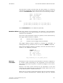
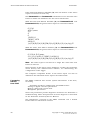
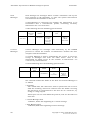
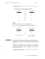
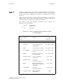
This is illustrated in the table below
Internal Data
FFn
FEn
Returned Data
122.324
23.8
335.14
2
3
0
2
3
0
122.32 or 1.22e2
23.8 or 2.38e1
335 or 3e2
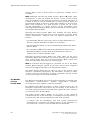
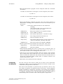
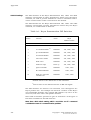
When the number of decimal places for returned data is reduced from
that of the maximum internal resolution, the last decimal place is
rounded upwards according to the magnitude of the next digit. This is
illustrated in the table below
Internal Data
FFn
FEn
Returned Data
23.877
23.872
125.94
2
2
0
2
2
0
23.88 or 2.39e1
23.87 or 2.39e1
126 or 1e2
Modifying the
The default format for data returned to the host by the Datataker is a
Data Item Format descriptive or conversational style, which is suitable for displaying
data directly on a host screen, for printing data, and for passing data
to purpose written or third party data acquisition software
packages.
The default format is illustrated by the following examples
Date 20/6/1992
Time 11:37:38
3V 12.279 mV
5PT385 -4.29 Deg C
2DS 1 State
8C 2391 Counts
The channel number indicates the source of the data, the channel
identifier indicates the type of signal or sensor, and the units text
indicates the engineering units for the data.
This default format for returned data items is user definable in a
number of ways, and is described in the following sections. These
commands are global, and specify the format for all returned data.
Channel
Number
The return of channel numbers is optional, and is determined by the
Channel Number Switch as follows
/N
Enable return of channel numbers (Default)
/n
Disable return of channel numbers
Copyright © 1993 dataTaker Pty Ltd
Document No. RM-003-A0
25
Free Format Mode for Returned Data
dataTaker
The Channel Number Switch defaults to /N when the Datataker is
initially powered up, hardware reset or executes a RESET command.
If the channel is located on an expansion module, or if a Datataker
channel has been addressed as module 0, then the channel number is
preceded by the module number. The module number is part of the
channel number, and is controlled by the Channel Number Switch.
Channel
Identifier
Channel identifiers can be returned from the Datataker only if the
channel numbers are being returned (/N). However the return o f
channel identifiers with the channel number is optional, and is
determined by the Channel Identifier Switch as follows
/C
Enable return of channel identifiers (Default)
/c
Disable return of channel identifiers
The Channel Identifier Switch defaults to /C when the Datataker is
initially powered up, hardware reset or executes a RESET command.
If return of channel numbers is disabled (/n), then return of channel
identifiers is also disabled.
Channel Names
The default method used by the Datataker for labelling returned data
by the channel number and channel identifier can be replaced by
unique channel names which are user definable.
The channel names are defined in text strings of up to 16 characters
as channel options. The following command for example
1TK("Boiler Temp")
names the channel in terms of the origin of the data.
If a name has been defined for a channel, then this is returned with
the data instead of the channel number and channel type. The return
of a defined channel name is disabled by the /c and /n Switch
commands.
The examples below illustrate the interactive effect of the Channel
Number Switch and Channel Identifier Switch on returned data
26
5PT385 –74.29 Deg C
5 –74.29 Deg C
–74.29 Deg C
–74.29 Deg C
/N/C
/N/c
/n/C
/n/c
Boiler Temp 125.5 Deg C
5 125.5 Deg C
125.5 Deg C
125.5 Deg C
/N/C
/N/c
/n/C
/n/c
Copyright © 1993 dataTaker Pty Ltd
Document No. RM-003-A0
dataTaker
Free Format Mode for Returned Data
Units Text
The return of units text is optional, and is determined by the Units
Text Switch as follows
/U
Enable return of units text (Default)
/u
Disable return of units text
The Units Text Switch defaults to /U when the Datataker is initially
powered up, hardware reset or executes a RESET command.
Date or Day
and Time
Labels and Units
The return of the Date or Day label and the Time label is determined
by the Channel Number Switch, and the return of the units of time is
determined by the Units Text Switch, as follows
/N
Enable return of Date or Day and Time labels (Default)
/n
Disable return of Date or Day and Time labels
/U
Enable return of time units (Default)
/u
Disable return of time units
The return of time units is only appropriate to the time formats o f
number of seconds since midnight and decimal hours (See Date and
Time Formats below).
Data Delimiter
Character
Each item of the data, the date or day, and the time, may be delimited
by a user definable data delimiting character.
If the Units Text Switch is enabled (/U), then each data item will be
delimited by CR/LF. If the data is being returned to a terminal screen
or printer, each data item will be written on a new line.
However if the Units Text Switch is disabled (/u), then each data item
is delimited by the character defined by the Parameter22 command.
The delimiter character is defined as the ASCII decimal code for the
required character. The command for example
P22=44
defines the data item delimiter to be the comma character (ASCII 44).
The default definition for Parameter22 is CR (ASCII 13) when units
text is enabled, and SPACE (ASCII 32) when units text is disabled.
Whenever Parameter22 is defined as a CR, then a LF is automatically
appended to produce a CR/LF new line sequence.
Examples of Data
Item Formats
The default data item format for returned data is defined by the
following commands
/U /N /C P22=13
Copyright © 1993 dataTaker Pty Ltd
Document No. RM-003-A0
27
Free Format Mode for Returned Data
dataTaker
which returns data in a descriptive format, and can be read directly
from a terminal screen or printer.
These default settings are automatically selected when the Datataker
is initially powered up, is reset, or executes a RESET command.
The default data item format is illustrated in the following examples
Date 12/06/92
Time 12:30:00
3V 12.279 mV
4PT385 –74.29 Deg C
5I 87.36 mA
2DS 1 State
3C 2391 Counts
Many combinations of settings for the data formatting Switches, the
data delimiter character, and the data resolution are possible to
change the data item format.
The most common alternative is
/u /n /c P22=44
which returns data in a format suitable for reading directly by host
software, as illustrated in the following examples
12/06/1992,11:30:00,12.279,–74.29,87.36,1,2391
The default data item format can require transmission of up to 20
characters for each data item returned to the host.
During real time data acquisition the default data item format w i l l
reduce the maximum scan rate, particularly if the communications
baud rate is low. This is because the logger will not scan a channel
group until all data from the previous scan has been sent to the host.
Disabling the channel number, channel identifier and units text,
and reducing the number of decimal places, will reduce each item o f
data to between 2 - 7 characters depending on the data type.
Data Block
Format
The data resulting from scanning more than one input channel is
returned from the Datataker to the host in a block format, which
comprises a grouping of the individual channel data.
The format of each data item in the block is user definable, and is
described above in Data Item Format.
The format of the data block is the same for real time data, and data
from the internal memory and memory card. Data returned from
memory can optionally include an end of stored data character.
28
Copyright © 1993 dataTaker Pty Ltd
Document No. RM-003-A0
dataTaker
Free Format Mode for Returned Data
The date and/or time of the scan may be included at the start of each
data block, depending on the setting of the Date Switch and the Time
Switch (See Date and Time Format below).
Each data block can also optionally be preceded by the address of the
Datataker returning the data. This allows blocks of data being
returned from a network to be identified.
Data Block Format The default data block format for data returned directly to the host
for Real Time Data in real time as input channels are scanned is illustrated below
Date dd/mm/yyyy
Time hh:mm:ss
nncc sddddd uu[delimiter]
..
..
..
..
..
..
..
..
[delimiter]
Date
Time
Data Items
Scan delimiter
character (Parameter24)
The format of the data block for real time data is user definable in a
number of ways.
The format of each data item in the block is user definable, and is
described above in Data Item Format.
Each block of data resulting from successive scans of input channels
is delimited by a user definable scan delimiter character.
If the Units Text Switch is enabled (/U), then the successive blocks o f
data are delimited by CR/LF. If returned data is displayed or printed,
then successive blocks of data are separated by a blank line.
If the Units Text Switch is disabled (/u), then the successive blocks o f
data are delimited by the character defined via the Parameter24
command. The delimiter character is defined as the ASCII decimal
code for the required character.
The command for example
P24=44
defines the block delimiter to be the comma character (ASCII 44).
The default definition for Parameter24 is CR (ASCII 13).
Whenever Parameter24 is defined as a CR, then a LF is automatically
appended to produce a CR/LF new line sequence.
Data Block Format The default data block format for data returned to the host from the
for
data memory or a memory card is the same as that returned in real
Stored Data
time, with the addition of an additional character after the last data
block is returned to signify the end of stored data.
The end of stored data character is defined by the Parameter25
command, as the ASCII decimal code for the required character.
Copyright © 1993 dataTaker Pty Ltd
Document No. RM-003-A0
29
Free Format Mode for Returned Data
dataTaker
The command for example
P25=42
defines the end of stored data character as an asterisk (ASCII 42).
The default is Parameter25=0 (NULL), and no character is returned.
Examples of Data
Block Formats
The default data block format for data returned in real time, or from
the data memory, is defined by the following commands
/U /N /C P22=13 P24=13
which returns data in a descriptive format, and can be read directly
from a terminal screen or printer.
These default settings are automatically selected when the Datataker
is initially powered up, is reset, or executes a RESET command.
The default data block format is illustrated in the following example
Date 12/06/1993
Time 11:30:00
3V -12.27 mV
1C 2391 Counts
5TK 162.2 Deg C
Date 12/06/1993
Time 11:45:00
3V -12.15 mV
1C 2267 Counts
5TK 159.8 Deg C
Many combinations of settings for the Switches and Parameters are
possible to define the data block format. The most common setting is
/u /n /c P22=44 P24=13
which returns data in a format suitable for reading directly by host
software, as illustrated in the following examples
12/06/1993,11:30:00,-12.27,2391,162.2
12/06/1993,11:45:00,-12.15,2267,159.8
The length of each block of data is determined by the number o f
channels scanned. Where two or more groups of channels are
scanned by different Scan Schedules, then whenever two or more o f
the scan times coincide the data is returned in separate blocks for
each Scan Schedule.
If the Units Text Switch is enabled (/U) the blocks are delimited by
CR/LF. If the Units Text Switch is disabled (/u) the blocks are then
delimited by the character defined at Parameter24.
30
Copyright © 1993 dataTaker Pty Ltd
Document No. RM-003-A0
dataTaker
Free Format Mode for Returned Data
The last block of data returned from the data memory or a memory
card will be terminated by the end of stored data character if one is
defined in Parameter25. This is illustrated in the following example
Date 12/06/1993
Time 11:30:00
3V -12.27 mV
1C 2391 Counts
5TK 162.2 Deg C
*
and
12/06/1993,11:30:00,-12.27,2391,162.2
12/06/1993,11:45:00,-12.15,2267,159.8
*
where Parameter25 is set to ASCII 42 (asterisk).
Datataker Address Each data block can be preceded by the address of the Datataker
returning the data. This allows blocks of data being returned from a
network to be identified.
The return of the Datataker address is optional, and is determined by
the Logger Address Switch as follows
/L
Enable return of logger address
/l
Disable return of logger address (Default)
The Logger Address Switch defaults to /l when the Datataker is
initially powered up, hardware reset or executes a RESET command.
If the return of logger address is enabled, then the data block will be
similar to the following examples
Logger 1
Time 11:30:00
3V -12.27 mV
1C 2391 Counts
5TK 162.2 Deg C
1,11:45:00,-12.15,2267,159.8
Data Item
Field Width
Normally the data returned by the Datataker to the host computer is
of variable width, depending on the magnitude of the actual data.
Each item of data may vary from 1 character in length, to 20 or more
characters.
However each item of data returned by the Datataker to the host
computer may optionally have a fixed field width, which may be set
to any width between 1 and 80 characters.
When data is returned in fixed field widths with the Channel Number
and the Channel Identification enabled (/N/C), then the channel
Copyright © 1993 dataTaker Pty Ltd
Document No. RM-003-A0
31
Free Format Mode for Returned Data
dataTaker
name is returned in a field of the defined length, and the actual data
is returned in a separate field of the defined length.
Parameter33 allows the user to define the width of the data field, i n
terms of the number of characters in the field for each data item.
Parameter33 has the following effects
• if the defined field is wider than the number of characters required
to represent the data item, then the characters are right justified i n
the field and the unused character positions to the left are filled
with spaces
• if the defined field is narrower than the number of characters
required to represent the data item, then the characters are right
truncated to fit into the field
• if Parameter33 is set to zero, then the default variable field width is
in effect
• if Parameter33 is set to a value greater than 80, it will be rejected
and Parameter33 will default to zero
These effects are illustrated below for the same item of data
1V 534.37 mV
1V
P33=0 (Default)
534.37 mV
1V 53 mV
P33=10
P33=2
The benefits of being able to define the field width for returned data
are as follows
• produces a tabulation of the data, to increase visual clarity of the
data returned to a terminal screen
• produces a tabulation of the data when directly dumped to printers
• provides a consistent number of characters for each data item,
which is of assistance when using third party software packages
which require fixed field data input.
The following example illustrates blocks of data returned in the
format defined by /n /c /u P22=32 P24=13, and without fixed field
width applied
18.8
18.9
18.8
18.7
32
18.7
16.0
16.6
16.0
3.498 0.000
138.08 0.000
153.27 0.000
0.192 0.000
Copyright © 1993 dataTaker Pty Ltd
Document No. RM-003-A0
dataTaker
Free Format Mode for Returned Data
The following example illustrates these same blocks of returned
data, in fixed field widths of 8 characters set by Parameter33=8
18.8
18.9
18.8
18.7
18.7
16.0
16.6
16.0
3.498
138.08
153.27
0.192
0.000
0.000
0.000
0.000
Each data item in each block is right justified and left space padded.
The effect is that the data for successive blocks is right aligned into
easily readable columns.
If the channel name or data is larger than the field width specified by
Parameter33, then the channel name or data is truncated from the
right. The $ text channel, Alarm text messages, Test results and
Status reports are not effected by the setting of Parameter 33.
Date and Time
Formats
The Datataker real time clock returns the Date or Day Number i n
three different formats, and the Time of day in three different
formats.
Date and Day
Number
Formats
The day can be returned as the Date or Day Number in one of three
formats. The format is specified by the Parameter31 command as
follows
• P31=0 selects the Day Number format as follows
Day 1269
• P31=1 selects the DD/MM/YYYY date format as follows
Date 23/06/1992
This is the default date format for 50 Hz line frequency operation, as
determined by the line frequency setting of the internal DIP switch.
• P31=2 selects the MM/DD/YYYY date format as follows
Date 06/23/1992
This is the default date format for 60 Hz line frequency operation, as
determined by the line frequency setting of the internal DIP switch.
Time Formats
The Time of day can be returned in one of three formats, which is
specified by the Parameter39 command as follows
• P39=0 (default) selects the hh:mm:ss time format as follows
Time 15:30:45
Copyright © 1993 dataTaker Pty Ltd
Document No. RM-003-A0
33
Free Format Mode for Returned Data
dataTaker
The character used to separate the hours, minutes and seconds can be
defined as any ASCII character by the Parameter40 command. The
default is ASCII 58 (:)
• P39=1 selects the seconds from midnight time format as follows
Time 23465 Secs
• P39=2 selects the decimal hours time format as follows
Time 22.38522 Hours
Decimal Day
The Datataker also has a Decimal Day format for time, which is a
decimal value for which the whole number is the day number, and
the fraction is the time of day expressed as a fraction of a day.
The Decimal Day is returned by reading the System Variable 12 by
the command
12SV
which returns the decimal day as follows
12SV
1269.9
If the global maximum number of significant digits is increased to
say 7 using the Parameter32=7 command, then greater resolution for
the fraction of the day can be obtained as follows
12SV
1269.953
Specifying 12SV(FF0) returns the day number only.
Date or Day
and Time
Labels and Units
The return of the Date or Day label and the Time label is determined
by the Channel Number Switch, and the return of the units of time is
determined by the Units Text Switch, as follows
/N
Enable return of Date or Day and Time labels (Default)
/n
Disable return of Date or Day and Time labels
/U
Enable return of time units (Default)
/u
Disable return of time units
The return of time units is only appropriate to the time formats o f
number of seconds since midnight and decimal hours.
Automatic Return The Datataker automatically records the Date or Day Number and
of
Time of data acquisition into the data storage memory when scan
Date and Time
data is logged. The Day Number or Date and Time of data acquisition
can optionally be returned with the logged data, even if D and/or T
channels were not included in the original scan command.
34
Copyright © 1993 dataTaker Pty Ltd
Document No. RM-003-A0
dataTaker
Free Format Mode for Returned Data
This automatic recording of the Day Number or Date and Time o f
data acquisition can also be used to return the Day Number or Date
and Time for each scan with real time scan data, even if D and/or T
channels were not included in the original scan command.
The return of automatically recorded Day Number or Date with the
logged or real time data is determined by the Date Switch Command
as follows
/D
Enable return of automatically recorded date
/d
Disable return of automatically recorded date (Default)
The Date Switch defaults to /d when the Datataker is powered up,
hardware reset or executes a RESET command.
The return of automatically recorded Time with logged or real time
data is determined by the Time Switch Command as follows
/T
Enable return of automatically recorded time
/t
Disable return of automatically recorded time (Default)
The Time Switch defaults to /t when the Datataker is powered up,
hardware reset or executes a RESET command.
When the Date Switch and the Time Switch are enabled, then the Day
Number or Date and Time of data acquisition is returned at the start
of the data block for each Scan Schedule in the application.
Formatting
Returns
from STATUS
The STATUS command returns system information to the host,
including
Datataker address and ROM Version
Scan schedules entered
Alarms entered
Polynomials and Spans entered
Data loggng state
Data points stored in internal memory, and unused memory
Data points stored in memory card, and unused card memory
Program stored in memory card
Switch settings
The information returned by the STATUS command has a default
format as follows
Datataker 0 Version 3.36
A B C,none Scan Schedules Active,Halted
3,0 Alarms Active,Halted
2 Polynomials/Spans Defined
Logging is OFF
13650,0 Internal Data Points Free,Stored
79265,1670 Card Data Points Free,Stored
4090,0 Program Characters Free,Stored
/a/C/d/E/f/h/J/K/l/M/N/o/Q/R/S/t/U/v/w/x/y/Z
Copyright © 1993 dataTaker Pty Ltd
Document No. RM-003-A0
35
Free Format Mode for Returned Data
dataTaker
If the Units Text Switch is disabled (/u), then the format of the status
report is truncated to data only.
The Parameter22 and Parameter24 Commands can be used with this
format to define the delimiters for the status information.
With the Units Text Switch disabled (/u) and Parameter22=13 and
Parameter24=13, the general status report is returned as follows
0,3.36
A B C,none
3,0
2
0
13650,0
76265,1670
4090,0
/a/C/d/E/f/h/J/K/l/M/N/o/Q/R/S/t/U/v/w/x/y/Z
With the Units Text Switch disabled (/u) and Parameter22=22 and
Parameter24=13, the general status report is returned as follows
0,3.20,A B C,none
3,0,3,0,13650,0,76265,0,4090,0,
/a/C/d/E/f/h/J/K/l/M/N/o/Q/R/S/t/U/v/w/x/y/Z
Note : The status report is returned in a single line when this data
format is selected.
These formats of the status report facilitates reading the Datataker
status directly into dedicated host software, for determining the
configuration of the logger.
The computer compatible format of the status report can also be
defined for the individual status reports described below.
Formatting
Returns
from TEST
The TEST command also returns system information to the host,
including
Datataker hardware configuration and ROM Version
Analog to digital converter parameters
Battery voltage and current draw
Multiplexer parameters
These test parameters provide diagnostic assistance if a Datataker is
malfunctioning. Their interpretation for fault diagnosis is described
in the Datataker Technical/Service Manual.
The information returned by the TEST command has a default
format which is illustrated overleaf
36
Copyright © 1993 dataTaker Pty Ltd
Document No. RM-003-A0
dataTaker
Free Format Mode for Returned Data
Datataker 524 Ver 3.36
Vos (mV) 0.027
Vfo (V) 7.442
Fc (kHz) 12.996
CMRR(db) 104.9
Vos3(mV) 0.211
Tos
1.0025
Ios (nA) 0
Ibia(nA) 8
Ibat(mA) -105.6
Vbat (V) 6.4
Vos✳(uA) -21
Vos+(uA) 11
Vos-(uA) 9
VosR(uA) -14
Vosd(uA) 14
PASS
The format of the test parameters can be changed with the Units Text
Switch and the Parameter24 Command.
If the Units Text Switch is enabled (/U) then the verbose format of the
test parameters as illustrated above is returned.
If the Units Text Switch is disabled (/u) then the brief format of the
test parameters as illustrated below is returned. The separator
between individual test parameters is defined by the Parameter22
Command, which by default is a space character.
524 3.36 0.027 7.442 12.996 104.9 0.211
1.0025 0 8 -105.6 6.4 -21 11 9 -14 14 PASS
Note : The test report is actually returned in a single line when this
brief format is selected.
If the separator character is set to a comma (Parameter22=44) then
the test parameters are returned as illustrated below
524,3.36,0.027,7.442,12.996,104.9,0.211,
1.0025,0,8,-105.6,6.4,-21,11 9,-14,14,PASS
Copyright © 1993 dataTaker Pty Ltd
Document No. RM-003-A0
37
Free Format Mode for Returned Data
dataTaker
Notes
38
Copyright © 1993 dataTaker Pty Ltd
Document No. RM-003-A0
dataTaker
Fixed Format Mode for Returned Data
Chapter 5
Fixed Format Mode for Returned Data
The Modes for
Returning Data
The Datataker normally returns data and information to the host
computer in the Free Format Mode by default. This is a descriptive o r
conversational style, which is suitable for displaying data directly
on a host screen, for printing data, and for passing data to purpose
written and third party data acquisition software packages.
The Free Format Mode has a default format for returned data and
information, which the user can change to suit the requirements o f
particular applications by using a number of data formatting
commands.
The Free Format Mode for returning data and system information is
described in Chapter 4.
The Datataker also has an alternative mode for returned data and
system information, which is specifically designed for transferring
data and information to purpose written and third party software
packages. This is the Fixed Format Mode, which is a fixed data
format that cannot be changed by the user.
The format of returned data is selected by the Data Format Switch
/H
Select Fixed Format Mode
/h
Select Free Format Mode (Default)
Following initial power up, a hardware reset, or executing a RESET
command, the Free Format Mode is selected.
Fixed Format Mode The responses from the Datataker are returned in a defined fixed
for
format, regardless of the current settings of the data formatting
Returning Data
switches and parameters. This mode is particularly suitable for
communication with data management software executing on a host
computer.
In Fixed Format Mode a number of the data formatting switches and
parameters are modified to provide the fixed output format, as
follows
/u
/n
/e
/r
Parameter22=44
Parameter24=13
Parameter38=46
No Units Text.
No Channel Identification.
No Echo.
No Returned Data.
Data item delimiter is a comma
Data block delimiter is a carriage return
Decimal locator is a period
The previous settings of these data formatting switches and
parameters in the Free Format Mode are saved on entry to Fixed
Format Mode, and are restored again on exit. While in Fixed
Copyright © 1993 dataTaker Pty Ltd
Document No. RM-003-A0
39
Fixed Format Mode for Returned Data
dataTaker
Format Mode, none of these switch or parameter settings can be
modified.
Note: Although selecting the Fixed Format Mode (/H) takes effect
immediately, it will not modify the format of any current output
from the Datataker at the time the command is received. Therefore i f
a block of data or system information is being returned when the
Fixed Format Mode is selected, output will continue in Free Format
Mode until completed. It is good practice to delay for up to five
seconds (depending on current activity of the Datataker) after
selecting the Fixed Format Mode, before assuming all returns will be
in the Fixed Format Mode.
Selecting the Fixed Format Mode also disables the Data Return
Switch (/r) to ensure that the host can be prepared to receive Fixed
Format information. However this has special implications as
follows
• the Datataker will not return any data or system information to
the host until the Data Return Switch is re-enabled
• the Data Return Switch can be re-enabled again while in the Fixed
Format Mode
• if a subsequent /H is issued when the Datataker is already in the
Fixed Format Mode, and the Data Return Switch has been reenabled, then it will be disabled again
Selecting the Fixed Format Mode only takes effect on the local
Datataker. When the Datataker is part of a network, then responses
from remote logger will not be in Fixed Format Mode unless this
mode has also been selected for the remote logger.
Note: It is advised that all loggers in a network are set to the Fixed
Format Mode (using ## /H and ## /h). This ensures that responses
from remote loggers will also be in Fixed Format Mode.
The Fixed Format Mode has no effect on any of the special serial
interface commands supported by the Datataker, and has no effect
on their responses (see Chapter 3). These commands operate outside
of any of the output modes of the Datataker.
The Benefits
of Fixed
Format Mode
The Fixed Format Mode has been provided primarily to simplify and
standardize communication
between
applications
software
executing on a host computer, and the Datataker.
The Fixed Format Mode guarantees a fixed response format for a l l
Datataker commands, and removes all uncertainty in the format o f
returned responses which would otherwise require the host software
to control the Free Format Mode.
The Fixed Format Mode makes use of some of the advanced
command features of the Datataker, to simplify the interpretation o f
returned data and system information. The mode provides
• a unique code for identifying data and system information
returned from a currently executing program in the Datataker, o r
returned from a memory card inserted into the Datataker.
40
Copyright © 1993 dataTaker Pty Ltd
Document No. RM-003-A0
dataTaker
Fixed Format Mode for Returned Data
• unique alert messages which indicate any program changes to the
Datataker, arising from any source, at the time the change is made.
Whenever the currently executing program is changed by
•
•
•
•
Alarm reprogramming
Card insertion
Network reprogramming
RS232 reprogramming
a message is returned to indicate that a program change has
occurred, and that the host may need to re-interrogate the
Datataker to determine the new currently active program. This
allows data management software to react to all external program
changes occurring in the Datataker.
• access to the profile of the currently active Datataker program
which is returning data, or of the program which previously logged
data onto a memory card inserted into the Datataker.
The STATUS10 (internal program) and the STATUS11 (card
program) commands return full details of the current data source,
which the host software can use to correctly prepare to receive that
data.
The information returned by the STATUS10 and the STATUS11
commands includes
• various system information such as whether a card is inserted,
the contents of the $ string, and the unique identifier of the
program
• a list of all scan schedules, including current Halt\Go status and
current trigger
• a list of all channels and channel variables in each scan
schedule, including each channel identifier, units text and
associated formatting information
These commands provide the information required to associate a l l
returned data to the individual channels or channel variables.
• Access to the available time range for logged data in internal
memory, or in a memory card inserted in the Datataker.
The STATUS12 (internal memory) and the STATUS13 (memory
card) commands return the time range of all currently logged data.
These commands enable detection of logged data, and intelligent
use of the UNLOAD command to access valid subsets of logged data
where required.
There are no facilities for error detection included in Fixed Format
Mode. Any message may be corrupted in transmission between the
Datataker and the host, and so any program decoding these messages
should take this fact into account.
If the Datataker is being used in an environment where corruption o f
transmitted responses is possible, then the communications should
make use of the Datataker Asynchronous RS232 Transport System
(DARTS) protocol.
Copyright © 1993 dataTaker Pty Ltd
Document No. RM-003-A0
41
Fixed Format Mode for Returned Data
dataTaker
If the DARTS protocol is invoked prior to selecting Fixed Format
Mode, then all communications can be guaranteed to be error free.
Fixed Format
Mode Message
Structure
The Fixed Format Mode consists of a number of unique messages.
There is a separate unique message structure for each type o f
response which can be received from the Datataker.
The Fixed Format Mode messages consist exclusively of printable
ASCII characters, except where non-printable characters exist i n
user defined text strings, or user defined alarm message delimiters
and terminators.
All of the Fixed Format Mode messages have a common structure as
follows
Leader : Body : Terminator
Leader
The Leader consists of the following fields
Type,Datataker Address,Type Specific Time Stamp,Type Specific Index
Type defines the information included in the message as follows
A
C
D
E
I
P
S
T
W
Alarm message
Program change message
Returned Data message
Error message
Information message
Parameter message
Status message
Test message
Password query message
Datataker Address is the address of the Datataker returning the message. The address is
in ASCII digits, in the range 0 to 31.
Type Specific Time Stamp. The time stamp can be up to ten ASCII digits, and is returned
as seconds elapsed since the Datatakerbase time of 1 January 1989. The interpretation of
the time stamp is dependent on the message.
The interpretations of the Type Specific Time Stamp are as follows
A
C
D
E
I
P
S
T
W
42
Time the alarm occurred.
Time the program change occurred.
Time of sampling of the data item(s) or the
time data return completed.
Time the error occurred.
Time the information was requested.
Time the parameter was requested.
Time the status was requested.
Time the test was requested.
Time the password was requested.
Copyright © 1993 dataTaker Pty Ltd
Document No. RM-003-A0
dataTaker
Fixed Format Mode for Returned Data
Type Specific Index. The interpretation of the index is dependent on the message type. It
can be up to two ASCII digits, and interpretations are as follows
A
C
D
E
I
P
S
T
W
Alarm number
Program change type code
0 - Change of card
1 - Change of logger program
Returned data type code
0 - Real-time data
1 - Logged data
2 - Unused
3 - End of data return (Indicates end of an
unload for logged data.)
Error number
Information number
Parameter number
Status message numbe
Test message number
Password message number
All fields of the Leader are always present in a Fixed Format Mode message.
Body
The message Body consists of a sequence of repeated fields specific to
the message type and index, as follows
field1 , field2 , field3 , field4 , etc
The fields may contain data as defined in the following table
Data Field
Contents
Integer
Value
Signed integer value
Range -2-31 to 231 -1
Floating
Point
Value
Floating point format with 5 significant digits,
which returns in engineering format when the
exponent is less than -4 or greater than 5 (max
significant digits).
Character
Single ASCII printable characters
Quoted String Double quote (") delimited strings. The double quote
cannot appear in the string. If the terminator exists
in any of the user defined strings, it is sent as two
space characters (ASCII 32).
Free
Format
String
A sequence of characters forming a string which
are not delimited by double quotes. Only printable
characters may appear in these strings.
Grouped
Data
Logical field grouping is managed by surrounding
the grouped data in < and > characters. Grouped
data may contain nested grouped data.
Copyright © 1993 dataTaker Pty Ltd
Document No. RM-003-A0
43
Fixed Format Mode for Returned Data
Terminator
dataTaker
The message terminator consists of two non-printable (control)
ASCII characters, which distinguishes the terminator from the
remainder of the message which is composed wholly of printable
ASCII characters.
<CR><LF>
The message terminator characters have the added advantage in that
they make the Fixed Format Mode strings easy to read on a simple
terminal or printer.
The message terminator string is guaranteed not to occur within the
other sections of the Fixed Format Mode message.
Fixed Format
Mode Message
Definition
The contents of each Fixed Format Mode message is described in the
following subsections, along with the interpretation and encoding o f
all fields in the message body.
Alarm
Messages
• Leader
A,Address,Time Stamp,Alarm Number
• Body
Alarm Action Text Quoted String.
• Example
A,0,84919,1:"Alarm - Channel value too high!":<CR><LF>
Alarm 1 from Datataker 0 at 84919 seconds
Alarm Action Text is "Alarm - Channel value too high!"
Program
Change
Messages
• Leader
C,Address,Time Stamp,Program Change Type Code
• Body
where Program Change Type Code is 0 for Change of card
Card Insertion Status
Card Identification
Integer
Interpreted as a bit map
Bit 0 - 1 for a card present
0 for no card
When Bit 0 indicates a card is present
Bit 2 - 1 indicates an external card
0 indicates an internal card
Quoted String
• Body
where Program Change Type Code is 1 for Change of program
Unique Program
Identification Code
44
Integer
Copyright © 1993 dataTaker Pty Ltd
Document No. RM-003-A0
dataTaker
Fixed Format Mode for Returned Data
• Examples
C,0,94225,0:5,"DATATAKER TEST DATA":<CR><LF>
Card Change message from Datataker 0 at 94225 seconds.
The new card contains data and must be treated as external.
The new card identification is "DATATAKER TEST DATA".
C,0,94419,1:4409:<CR><LF>
Program Change message from Datataker 0 at 94419 seconds.
The Unique Program Identification Code for the program now
in the Datataker is 4409.
Returned
Data
Messages
• Leader
D,Address,Time Stamp,Returned Data Type Code
• Body
where Returned Data Type Code is 0 for Realtime data
where Returned Data Type Code is 1 for Logged data
Schedule Identifier
Character A,B, C, D, X or Z
Offset within the
schedule of the first
returned channel
Integer
The ordering is defined to be the
order of channel declaration.
When long channel lists are
returned in multiple messages,
offset indicates the position of the
first returned channel in the
original declaration.
List of at least one,
but usually many
sampled channel data
Floating Point
• Body
where Returned Data Type Code is 3 for End of data return
No Fields
• Examples
D,0,95612,0:A,0,91.991,23.100,-606410.0:<CR><LF>
Data Return message from Datataker 0.
The returned data was sampled at 95612 seconds.
The data is realtime data.
The data is from scan schedule A.
The data are for the first, second and third channels which had
originally been declared for scan schedule A.
The data items follow in order.
D,0,85110,1:B,0,91.991,23.100,-606410.0:<CR><LF>
Data Return message from Datataker 0.
The returned data was sampled at 85110 seconds.
Note: The time stamp for logged data will be different
to the current time of the Datataker.
The data is logged data.
The data is from scan schedule B.
Copyright © 1993 dataTaker Pty Ltd
Document No. RM-003-A0
45
Fixed Format Mode for Returned Data
dataTaker
The data are for the first, second and third channels which had
originally been declared for scan schedule B.
The data items follow in order.
D,0,95614,3::<CR><LF>
End of Returned Data message from Datataker 0 at 95614 secs.
This message signals the end of a data return, and the time
stamp is the time at which the data return was completed.
Error
Messages
• Leader
E,Address,Time Stamp,Error Number
• Body
Datataker Error Text
Quoted String.
• Example
E,0,85884,20:"illegal character(s)":<CR><LF>
Error message from Datataker 0 at 85884 seconds.
Datataker error message 20.
Datataker error text is "illegal character(s)".
Information
Messages
• Leader
I,Address,Time Stamp,Information Number
• Body
Unique Program
Identification Code
Integer
Card Insertion Status
Integer
Interpreted as a bit map
Bit 0 - 1 for a card present
0 for no card
When Bit 0 indicates a card is present
Bit 2 - 1 indicates an external card
0 indicates an internal card
Card Identifier
Quoted String
• Example
I,0,85886,20:24708,1"DATATAKER TEST DATA":<CR><LF>
Information Message from Datataker 0 at 85886 seconds.
Information Message number 20
The Unique Program Identification Code for the program on
the memory card is 24708.
The new memory card is blank, and therefore internal.
The new card's identification is "DATATAKER TEST DATA".
Parameter
Messages
• Leader
P,Address,Time Stamp,Parameter Number
• Body
Current Parameter Value Integer
46
Copyright © 1993 dataTaker Pty Ltd
Document No. RM-003-A0
dataTaker
Fixed Format Mode for Returned Data
• Example
P,0,86222,24: 13:<CR><LF>
Parameter message from Datataker 0 at 86222 seconds.
Parameter number 24.
The current value of Parameter 24 is 13.
Status
Messages
• Leader
S,Address,Time Stamp,Status Message Number
Note: The STATUS command produces sequential return of the
status messages 1 to 9 inclusive from the Datataker.
The body contents of each of the 9 different status messages are
detailed below.
• Body
where Status Message Number is 1
Datataker Address
Datataker Version
Integer
Integer
• Body
where Status Message Number is 2
Active Schedules
Inactive Schedules
Free Format String
Free Format String
• Body
where Status Message Number is 3
Active Alarms
Inactive Alarms
Integer
Integer
• Body
where Status Message Number is 4
Number of defined
polynomials/spans
Integer
• Body
where Status Message Number is 5
Current logging state
Integer - 0 if LOGOFF
- 1 if LOGON
• Body
where Status Message Number is 6
Internal Memory Free
Integer
Internal Memory in Use Integer
• Body
where Status Message Number is 7
Card Memory Free
Integer - 0 if no card inserted
Card Memory in Use
Integer - 0 if no card inserted
Copyright © 1993 dataTaker Pty Ltd
Document No. RM-003-A0
47
Fixed Format Mode for Returned Data
dataTaker
• Body
where Status Message Number is 8
Card Program
Characters Free
Integer - 0 if no card inserted
Card Program
Characters in Use
Integer - 0 if no card inserted
• Body
where Status Message Number is 9
Switch Settings
Free Format String
Note: The STATUS command produces sequential return of the
status messages 1 to 9 inclusive from the Datataker.
The body contents of each of the 9 different status messages are
illustrated in the following examples below
• Examples of Status Messages 1 to 9
All Status Messages in the following examples are returned
from Datataker address 0 at 157284 seconds.
S,0,157284,1:0,3.24:<CR><LF>
Datataker Address is 0.
Datataker Version is 3.24.
S,0,157284,2:Z A,none:<CR><LF>
Schedules Z and A are active.
There are no inactive schedules.
S,0,157284,3:1,0:<CR><LF>
There is 1 alarm active.
No alarms inactive.
S,0,157284,4:0:<CR><LF>
No polynomials or spans defined.
S,0,157284,5:0:<CR><LF>
Current logging state is LOGOFF.
S,0,157284,6:13638,12:<CR><LF>
There are 13638 data points free in internal memory.
There are 12 data points stored in internal memory.
S,0,157284,7:0,0:<CR><LF>
S,0,157284,8:0,0:<CR><LF>
There is no memory card currently inserted, therefore there
are no memory card data storage or program storage statistics.
S,0,157284,9:
/a/C/d/e/f/H/J/K/l/M/n/o/Q/R/S/T/u/v/w/x/y/Z:<CR><LF>
The current settings for the Datataker switches.
(This message is returned in a single line, although shown here
as two lines for layout purposes.)
48
Copyright © 1993 dataTaker Pty Ltd
Document No. RM-003-A0
dataTaker
Fixed Format Mode for Returned Data
• Body
where Status Messages Numbers are 10 and 11
Status 10 returns a profile of the current program active in the
Datataker, and the realtime or logged data which it generates.
Status 11 returns a profile of the program which generated the data
stored in a memory card inserted in the Datataker. If no memory
card is inserted, then a null profile is returned.
Unique Program
Identification Code
Integer
Base Year of Datataker
Integer
Provision is made for returning the
base year as a definable value.
Not yet supported by the Datataker.
Resolution of time
stamps returned
Always 1 - Seconds.
Provision has been made for greater
time resolution. Not yet supported by
the Datataker.
Card Insertion Status
Integer
Interpreted as a bit map
Bit 0 - 1 for a card present.
0 for no card.
When Bit 0 indicates a card is present
Bit 2 - 1 indicates an external card.
0 indicates an internal card.
Current $ String
Quoted String.
A Schedule
Grouped Field.
B Schedule
Grouped Field.
C Schedule
Grouped Field.
D Schedule
Grouped Field.
X Schedule
Grouped Field.
• Body
of a Schedule Grouped Field
Schedule Identifier
Character
A, B, C, D or X
If there are no channels declared for the scan schedule, then
there are no further fields.
If there are channels defined for the scan schedule, then the
following fields are included in the group.
Current Scan
Schedule Trigger
Copyright © 1993 dataTaker Pty Ltd
Document No. RM-003-A0
Quoted String
49
Fixed Format Mode for Returned Data
dataTaker
Scan Schedule
Halt\Go Status
Character
G - Going
H - Halted
C - Card
List of Declared
Channels
Grouped Field
• Body
of a Declared Channel Grouped Field
Channel
Identification
Quoted String
Either as specified by user
text or the default.
Channel Units Text
Quoted String
Returned Data Format
Integer
0 - Numeric
1 - Time
2 - Date
3 - Text
4 - Time stamp
Returned Data
SubFormat
Integer
For Numeric
0 - FF, 1 - FE, 2 - FM
For Time
0 - 24 Hr in hh:mm:ss
9 - Decimal hours as
Hour of day.Hour fraction
11 - Decimal second as
Second of day.Second fraction
For Date
4 - mm/dd/yyyy
10 - dd/mm/yyyy
17 - Elapsed days from base year
For Text
Always 0
For Time Stamp
Always 0
Numeric Data Format
- Significant Digits
Integer
Numeric Data Format
- Decimal Places
Integer
Returned Data Type
Integer
1 - Realtime only (NL)
2 - Logged only (NR)
3 - Both Logged and Realtime
Status 10 returns a profile of the current program active in the
Datataker, and the realtime or logged data which it generates.
Status 11 returns a profile of the program which generated the data
stored in a memory card inserted in the Datataker. If no memory
card is inserted, then a null profile is returned.
50
Copyright © 1993 dataTaker Pty Ltd
Document No. RM-003-A0
dataTaker
Fixed Format Mode for Returned Data
• Examples of Status Messages 10 and 11
S,0,157308,10:21430,1989,1,0,"Boiler Data",
<A,"5S",G,<"1V","mV",0,0,5,3,3>,<"3R","Ohms",0,0,5,3,3>>,
<B>,<C>,<D>,<X>:<CR><LF>
Status Message from Datataker 0 at 157308 seconds.
Status Message 10.
The Unique Program Identification Code is 21430.
The Base Year of the Datataker is 1989.
Time Stamps are returned in seconds from Base Year.
There is no card inserted in the Datataker.
The $ string is "Boiler Data".
Schedule A has channels declared
It has a 5S trigger
It is currently going
It has the following channels
Channel 1V
Units Text is "mV"
Data returned in Numeric Format
Free Format as FF, 5 sig digits and 3 decimal places
Data is returned as both realtime and logged data
Channel 3R
Units Text is "Ohms"
Other settings as for 1V
S,0,157320,11:21430,1989,1,7,"Boiler Data",
<A,"5S",C,<"1V","mV",0,0,5,3,3>,<"3R","Ohms",0,0,5,3,3>>,
<B>,<C>,<D>,<X>:<CR><LF>
Status Message from Datataker 0 at 157320 seconds.
Status Message 11.
Unique Program Identification Code is 21430.
The same program as the example above, but stored on a card.
The only differences are that the memory card insertion status
indicates that a memory card containing data is inserted in the
Datataker (7), and the status of schedule A is C which indicates
that the schedule's data is on the card.
• Body
where Status Messages Numbers are 12 and 13
Status 12 returns the available time range of data logged in the
internal memory of theDatataker.
Status 13 returns the available time range of data logged in a
memory card inserted into the Datataker. If no memory card is
inserted, then both fields are returned as zero.
Earliest time of
available logged data
Integer
Value interpreted as seconds elapsed
since the Datataker base time of
1 January 1989.
Latest time of
available logged data
Integer
Value interpreted as seconds elapsed
since the Datataker base time of
1 January 1989.
Copyright © 1993 dataTaker Pty Ltd
Document No. RM-003-A0
51
Fixed Format Mode for Returned Data
dataTaker
• Examples of Status Messages 12 and 13.
S,0,157580,12:124200,138800:<CR><LF>
Status Message from Datataker 0 at 157580 seconds.
Status Message 12.
The available time range of data logged in the internal memory
is base time + 124200 to base time + 138800.
S,0,148950,13:234780,235648:<CR><LF>
Status Message from Datataker 0 at 157580 seconds.
Status Message 13.
The available time range of data logged in the memory card is
base time + 234780 to base time + 235648.
Test
Messages
• Leader.
T,Address,Time Stamp,Test Message Number
• Body
where Test Message Number is 0
Datataker
Configuration
Integer
Datataker Version
Integer
• Body
where Test Message Numbers are 1 to n, where n is dependent
on the Datataker version.
Current Test
Parameter Value
Floating Point
Pass\Fail Indicator
Integer
1 for Pass
0 for Fail
There are m internal test messages, where m is dependent on the
Datataker version, which are never returned in response to the TEST
command. One final message numbered n + m +1 is returned which is
the overall pass\fail status.
• Body
where Test Message Number is (n + m+1)
Overall System
Pass\Fail Indicator
Integer
1 for Pass
0 for Fail
• Examples
T,0,87970,0:52,3.24:<CR><LF>
Test Message from Datataker 0 at 87970 seconds.
Test Message 0.
Datataker Configuration is 52.
Datataker Version is 3.24.
52
Copyright © 1993 dataTaker Pty Ltd
Document No. RM-003-A0
dataTaker
Fixed Format Mode for Returned Data
T,0,87972,2:7.514,1:<CR><LF>
Test Message from Datataker 0 at 87972 seconds.
Test Message 2.
Input Voltage for VCO = 0Hz is 7.514
Test 2 passed.
T,0,87973,21:1:<CR><LF>
Test Message from Datataker 0 at 87973 seconds.
Test Message 21.
Overall test passed.
Password
Query Messages
• Leader
W,Address,Time Stamp,Password Message Number
• Body
where Password Message Number is 0
Is Password Set?
Integer
1 for password defined
0 for no password defined
• Example
W,0,95907,0:1:<CR><LF>
Password Query response from Datataker 0 at 95907 seconds.
There is a password currently defined on this logger.
Suggested Models
for use of Fixed
Format Mode
There are two suggested models for use of the Fixed Format Mode
when supervising a Datataker data logger from application software
running on a host computer.
• The Programmed Model
• The Query Model
Programmed
Model
When the Datataker program is downloaded by the application
software running on the host computer each time the application is
run, the Programmed Model is appropriate.
The application software has full supervisory control of the
Datataker, including full knowledge of the data being returned.
•
•
•
•
Run the application program on the host computer
Issue /H to enter Datataker into Fixed Format Mode
Download the program to the Datataker
Check for the error messages indicating that the program was
received correctly
• If the program was received correctly, issue /R
• Process all returned data
• If a program change message is received at any time it is possible
that the channels declared in the active program on the Datataker
may have changed. It is always necessary to re-issue the
Copyright © 1993 dataTaker Pty Ltd
Document No. RM-003-A0
53
Fixed Format Mode for Returned Data
dataTaker
appropriate STATUS command to determine the currently declared
channels.
Query Model
When the application program is not responsible for
programming of the Datataker, the Query model is appropriate.
the
Generally the Datataker has been programmed by some other
agency, and the application software must determine the
configuration of the Datataker programs in order to interpret the
returning data.
•
•
•
•
Run the application program on the host computer
Issue /H to enter Datataker into Fixed Format Mode
Issue STATUS1 to ensure communication is still possible
If communication is established
Issue STATUS10 to analyse the program running in the Datataker,
which may be returning data in real time, logging data in internal
memory, or simply has data in internal memory or an internal
memory card to unload
If an external memory card is inserted, issue STATUS11 to analyse
the program which stored data on a memory card
An 'internal memory card' is one in which data from the program
currently executing in the Datataker is stored.
An 'external memory card' is one in which data has been stored by
another program either running in this Datataker, or in another
Datataker.
• If necessary check that the program is the one expected by returning
the unique program identification code, and comparing this with
the previously saved identification code of the Datataker program
• Analyse the scan schedule and channel lists to determine the
mapping of returned data to the channels declared in the active
program
• Issue /R to receive real-time data or U to receive logged data
• Use the analysis results to associate the returned data with the
channels being scanned
• If a program change message is received at any time it is possible
that the channels declared in the active program on the Datataker
may have changed. It is always necessary to re-issue the
appropriate STATUS command to determine the currently declared
channels.
54
Copyright © 1993 dataTaker Pty Ltd
Document No. RM-003-A0
dataTaker
Datataker Asynchronous RS232 Transport System
Chapter 6
Datataker Asynchronous RS232 Transport System
This chapter describes the Datataker Asynchronous RS232
Transport System (DARTS) protocol available in all Datataker data
loggers with ROM versions 3.00 and later.
The chapter is intended both for readers who wish to use the DARTS
protocol in their own applications programs, and for those who wish
to use the DARTS protocol to implement a Datataker driver for third
party applications software.
The chapter is not intended as a tutorial on the specification and
implemention communications protocols. It is assumed that the
reader either has a basic knowledge of communication protocols, o r
has access to other more general texts on communication protocols.
DARTS
Protocol
By default the Datataker communicates with a host computer using
simple ASCII text strings, without any error checking or error
management facilities.
Where data intergity over the communication link is required, the
DARTS protocol will provide error checking and error management.
Data integrity is usually necessary when the Datataker is
communicating from a remote site via a telemetry system, to
applications software running on a host computer.
Enabling
DARTS
Communication using the DARTS protocol
command
is enabled by the
^Z1PMODE=ONE
Note : The ^Z indicates the Control Z character which must be sent to
the Datataker as ASCII 26, and not literally as circumflex Z.
This command can be sent to the Datataker from DeTerminal and
DeCipher Plus using the interactive command as follows
\0261PMODE=ONE
where \026 is translated to a Control Z character when the command
is transmitted.
The Datataker signifies that DARTS has been enabled by returning
ENABLED
All subsequent commands issued to the Datataker must obey the
protocol, to be accepted by the Datataker. The exceptions are the
Copyright © 1993 dataTaker Pty Ltd
Document No. RM-003-A0
55
Datataker Asynchronous RS232 Transport System
dataTaker
Special Serial Interface Commands (see Chapter 3), which are
interpreted directly at the serial interface of the Datataker.
All subsequent data and information returned by the Datataker w i l l
also obey the protocol.
Disabling
DARTS
Communication using the DARTS protocol is disabled by the
command
^Z0PMODE=ZERO
The leading character after ^Z is numeric 0 (zero), and not the literal
character uppercase O.
Note : The ^Z indicates the Control Z character which must be sent to
the Datataker as ASCII 26, and not literally as circumflex Z.
This command can be sent to the Datataker from DeTerminal and
DeCipher Plus using the interactive command as follows
\0260PMODE=ZERO
where \026 is translated to a Control Z character when the command
is transmitted.
The Datataker signifies that DARTS has been disabled by returning
DISABLED
All subsequent commands issued to the Datataker must no longer
obey the protocol, to be accepted by the Datataker.
All subsequent data and information returned by the Datataker w i l l
be as simple ASCII text strings.
Overview
of DARTS
When the DARTS protocol is enabled, all transmissions from the
host computer to the Datataker, and from the Datataker to the host
computer, include extra information to allow detection of errors.
It is not appropriate to use the DARTS protocol when communicating
with the Datataker from DeTerminal, or other terminal programs.
When an error is detected in a transmission, the information is then
retransmitted a finite number of times or until the information is
received correctly. If all retries are corrupted, then the information
is lost and the error is recorded in Parameter12 which maintains a
record of the number of transmission errors. The Datataker w i l l
then attempt to transmit any further information ready for output.
The DARTS protocol automatically manages flow control. When the
DARTS protocol is enabled, the Datataker ignores any software flow
(specifically XON/XOFF). Any attempt by the host computer to use
XON/XOFF will be ignored.
56
Copyright © 1993 dataTaker Pty Ltd
Document No. RM-003-A0
dataTaker
Datataker Asynchronous RS232 Transport System
If the DARTS protocol is supported by a terminal program (such as
the Command module of DeCipher Plus) it is possible to
communicate directly with the Datataker with DARTS protocol
enabled. The terminal program must manage the host end of the
protocol. The use of the DARTS protocol is transparent to the user,
and there is no effect on the available Datataker command set.
Physical Aspects of The DARTS protocol supports a single point to point connection
the
between a host computer and a Datataker data logger. The protocol
DARTS Protocol
will operate over any RS232 compatible connection between the
computer and the Datataker.
The DARTS protocol places no additional physical requirements on
the RS232 connection, and so no special cables are required. A n y
connection which can be used to communicate with a Datataker i n
ASCII mode, can also be used to communicate with a Datataker using
the DARTS protocol.
DARTS
Message
Definitions
The communication between a host computer and a Datataker is full
duplex. The DARTS protocol also operates in full duplex mode,
allowing simultaneous transmission of information in both
directions.
The DARTS protocol is based solely on the standard ASCII character
set. Some control characters are used to identify messages and
message types, and so should not be used in text strings sent between
the Datataker and the host computer while the DARTS protocol is
enabled.
These reserved characters are
ASCII 01
ASCII 02
ASCII 03
SOH
STX
ETX
^A in Datataker strings
^B in Datataker strings
^C in Datataker strings
Whenever any of these characters are used in text strings, the DARTS
protocol detects their presence in the string and replaces them with
the ✳ character. In this way they do not interfere with the normal
operation of the DARTS protocol.
In addition, the following characters also should not be sent to a
Datataker while the DARTS protocol is enabled
ASCII 00
NUL
^@ in Datataker strings
Ignored by the Datataker
ASCII 26
SUB
Prefix to Special Serial Interface Commands. The
characters following will be interpreted as a special
command, and the message will fail.
ASCII 7F
DEL
The Delete character. This is also treated as a Special
Serial Interface Command, and the message will fail.
There are two distinct types of messages in the DARTS protocol, Data
Messages and Control Messages
Copyright © 1993 dataTaker Pty Ltd
Document No. RM-003-A0
57
Datataker Asynchronous RS232 Transport System
Data
Messages
dataTaker
Data messages are messages which contain commands sent by the
host computer to the Datataker, or data and system information
returned from the Datataker to the host.
A Data Message is constructed by framing the information to be
transmitted into a transmission packet, containing ancillary
information for error detection.
A Data Message has the following general format
Preamble
<255 (FF)>
<255 (FF)>
Control
Messages
Data
Message
Start
<02 (STX)>
Message
Number
Message
Message
End
CRC
<20>-<7E>
(Printable)
Datataker
command
or data.
Up to 255
message
characters
<03 (ETX)>
4 hex
digits as
ASCII
characters
Control Messages are messages used exclusively by the DARTS
protocol to control the transfer of information between the host
computer and the Datataker.
A Control Message is used to acknowledge the correct or incorrect
receipt of messages sent from the other device. This is the
mechanism by which errors in the transfer of information are
corrected by retransmission.
A Control Message has the following general format
Preamble
<FF><FF>
Control
Message
Start
<01 (SOH)>
Message
Number
Ackn.
Status
CRC
<20>-<7E>
(Printables)
<06 (ACK)>
or
<15 (NAK)>
4 hex
digits as
ASCII
characters
The rationale behind the fields in the Data and Control Messages is
as follows
• Preamble
Two <ASCII 255, FF> characters used to synchronise the receiver
with the incoming characters. Ensures that the UART receiving
the characters is synchronised to the first bit of a character, by
acting as a long stop bit.
These bytes are not used within the protocol, and are discarded on
detection.
• Control Message Start
<ASCII 01, SOH> The beginning of a control message.
• Data Message Start
<ASCII 02, STX> The beginning of a data message.
58
Copyright © 1993 dataTaker Pty Ltd
Document No. RM-003-A0
dataTaker
Datataker Asynchronous RS232 Transport System
• Message Number
ASCII characters in the range 20 to 7E Hex, indicating a sequence
number for the message. This is used to ensure that all the
information is received once only and in the correct order.
Note that 7F Hex, the Delete character, is handled as a Special
Serial Interface Command, and so cannot be used as a message
number.
• Message
ASCII characters in the ranges of 04 to 7E Hex and 80 to FF Hex
representing the dialogue with the Datataker.
Note :
00 Hex is ignored
01 to 03 Hex will be transformed to ✳ if detected in a message
26 and 7F Hex are Special Serial Interface Command
characters and will be interpreted outside of the protocol. The
message will fail.
The maximum length of any message is 255 characters. A n y
messages longer than 255 characters can be split up into separate
packets, and will be reconstituted in the Datataker.
• Acknowledge Status
<ASCII 06, ACK> Notification of a message received correctly.
<ASCII 15, NAK> Notification of a message received incorrectly.
• Message End
<ASCII 03, ETX> The end of a data message.
• CRC
The CRC-CITT standard 16 bit cyclic redundancy check expressed
as four hex digits in ASCII. The CRC is calculated over all other
fields of a message except the preamble and the CRC itself. This
CRC will catch all corruption errors within a single message. The
algorithm used is presented at the end of the Chapter.
DARTS
Message
Sequencing
Messages in the DARTS protocol are sent in groups called sessions. A
session begins when two devices using the DARTS protocol correctly
send/receive an initial message/acknowledgment pair. This is the
first actual data which is to be transferred between the devices. On
receipt of this initial message and its positive acknowledgment, both
devices reset their 'last correct message number' so that these agree.
The session is then in progress.
Two special message numbers (see Fault Behaviour Analysis, case 9)
have been set aside for initial messages, 20 and 21 Hex. These
message numbers are not used again until a new session is
commenced (the wrap around sequence is 7D, 7E, 22, 23...).
Note that a session may be started by either the host computer
sending a command to the Datataker, or the Datataker returning
data or system information to the host computer.
The DARTS protocol is a send and wait ARQ protocol. The host must
ensure that each command sent to the Datataker is received correctly
before the next command is sent, to guarantee an execution sequence.
Copyright © 1993 dataTaker Pty Ltd
Document No. RM-003-A0
59
Datataker Asynchronous RS232 Transport System
dataTaker
Each new message to be sent is allocated the next available message
number. After the message is transmitted, the sender must wait for
one of three responses from the receiver as follows
• Acknowledgment of the transmitted message number.
The message has been correctly received if the message number o f
the acknowledgment matches the message number of the
transmitted message. The sender can now send the next message (if
there is one) with the next available message number. If the message
number differs from that expected, the acknowledgement is
discarded.
• Negative Acknowledgment of the transmitted message number.
The message was incorrectly received (most likely with respect to its
CRC). The message must be retransmitted with the same message
number.
• No response received within a time out period.
The message is assumed lost. The message must be retransmitted
with the same message number.
The message will be checked by the receiver for corruption using the
CRC. If the message has been received correctly, then the message
number is checked against the last one received. If the message
number is different, or it is one of the two initial messages, then the
message is accepted and an acknowledgement is returned.
The only circumstance in which a message is discarded by the
receiver is if the message has the same message number as the last
message received. The message is deemed to be a retransmission o f
an already received message.
The wait for acknowledgment imposed by the protocol after message
transmission results in effective flow control on the connection.
There is only ever need to set aside space for a single message, since
no other message will be transmitted until an acknowledgment has
been received or the transmitter times out.
Retransmission is limited to five retries by the Datataker. If after
five retries no positive acknowledgment has been received, the
Datataker will give up and attempt to transmit any other
outstanding messages. The maximum time spent on any one message
is limited to five time out periods.
A session is explicitly finished when
• Protocol mode is exited on the Datataker
• A new session is started
• by sending an initial message to the Datataker
• in response to the Datataker being RESET (in which case the
DARTS protocol must be re-enabled).
• when reconnecting to a Datataker which has the DARTS
protocol already enabled.
Note that a session is never explicitly finished by the Datataker.
If the connection is lost for a period of time, the host computer must
always resynchronise message numbers with the Datataker in case
60
Copyright © 1993 dataTaker Pty Ltd
Document No. RM-003-A0
dataTaker
Datataker Asynchronous RS232 Transport System
the Datataker is attempting to send information to the host as part
of the old session.
This can be done by
• Beginning a new session by sending an inital message, or by
re-enabling the DARTS protocol.
• Waiting for a response from the Datataker and send the approriate
acknowledgement for the received message number.
Implementation of Enabling the DARTS protocol on the Datataker does not affect any o f
the DARTS
the Switch or Parameter settings of the Datataker, except that the
Protocol by
command Echo Switch is disabled (/e). All Datataker commands
the Datataker
behave in the same way, and data is returned as requested.
The Datataker DARTS protocol driver has two separate modules for
the sending and receiving of DARTS messages. The Transmitter
Module controls the transfer of information to the host computer
from the Datataker. The Receiver Module controls receipt o f
messages from the host computer.
Each module requires access to the transmit and receive functions o f
the physical RS232 connection as follows
• The transmitter module requires access to transmit data messages,
and to receive control messages.
• The receiver module requires access to receive data messages, and to
send control messages.
Access to the send and receive lines of the RS232 connection is
controlled by a third module, the RS232 Services Module, which
manages contention.
RS232
Services Module
All messages must be transmitted according to the following rules
• All messages must be sent as complete entities.
This means that the longest message transmission time must be
part of the acknowledgment timeout. An acknowledgment may
have to wait for the transmission of the longest message prior to
being transmitted itself.
• Any outstanding acknowledgments have priority over messages.
There should only ever be one outstanding acknowledgment, due to
the send and wait ARQ nature of the protocol.
All messages to be sent are passed to the RS232 Services Module for
transmission. Queuing is managed by a control flag, which
determines whether either the transmitter or the receiver module is
currently having a message transmitted. Any subsequent
transmission requests must wait until the current transmission is
completed.
On completion of a transmission, the module which just used RS232
services must allow the other module to make use of the services
ensuring a 'fair share' of the transmission medium. This does not
restrict acknowledgment of received messages, since the send and
Copyright © 1993 dataTaker Pty Ltd
Document No. RM-003-A0
61
Datataker Asynchronous RS232 Transport System
dataTaker
wait ARQ guarantees that only one message can be awaiting an
acknowledgment, hence there can only ever be one outstanding.
When the RS232 Services Module is idle, transmission request
acknowledgments are always given priority over data messages, to
increase throughput.
All incoming characters are processed into messages by the RS232
Services Module. The message start character indicates the
destination of the message as follows
• a data message start indicates the Receiver Module
• a control message start indicates the Transmitter Module
The preamble and start characters are discarded, and the remainder
of the message is passed on to the destination module for further
processing.
If during reception of a message a new start character is received,
then the current message is abandoned. The receive process begins
again with the new message.
Transmitter
Module
The Transmitter Module provides a FIFO output queue, which
replaces the standard Datataker RS232 output buffer when the
DARTS protocol is enabled.
The Transmitter Module continually checks its queue for messages
to send. When a message arrives, it is framed into a DARTS message
and sent using the RS232 Services Module.
Message framing involves processing the message to replace any
ASCII protocol control characters in the message with ASCII 2A Hex
(✳), and addition of the DARTS protocol control characters. The
message can be then be sent. When the message has been sent, the
Transmitter Module then waits for the RS232 Services Module to
supply a received acknowledgment within a time out period.
The acknowledgement time out period is based on
Message transmission time
+ Acknowledge transmission time
+Message processing time (5 seconds)
The Transmitter Module follows the DARTS protocol sequencing
rules to determine if the message has been received correctly.
Once the message has been determined to be received correctly, or the
transmitter has reached its maximum retries (five in the Datataker),
the output queue is checked for the next message.
62
Copyright © 1993 dataTaker Pty Ltd
Document No. RM-003-A0
dataTaker
Datataker Asynchronous RS232 Transport System
Initial State
Actions
{Message Number <- 21}
Initialised
Message queued for transmission
Idle
Actions
{Check Output message queue}
Transmitting
Retry Count > Maximum
+ Ack & message number match
Actions
{Retry Count += 1}
{Transmit Message}
Message Transmitted
- Ack & message number match
or time out
Waiting for Ack.
Actions
{Process incoming acknowledge}
{- Message Number doesn't match - Ignore}
{- Message Number does match - Message Number += 1}
{Manage time out}
Transmitter Module State Transitions.
Receiver
Module
The Receiver Module provides processing for all data messages
received from the host computer. All messages passed on by the
RS232 Services Module conform to the protocol message framing
rules. The messages are passed on with the preamble and the start
characters stripped off. The Receiver Module is responsible for
checking the CRC of the received message.
When a data message is received correctly (the calculated CRC
matches the transmitted CRC and the message number is acceptable),
the Receiver Module processes the contents of the message and then
queues a positive acknowledgment control message, with the
message number of the received message, for return to the host
computer. When a data message is received with errors, the receiver
module queues a negative acknowledgment control message for
return to the host computer. The erroneous message is discarded.
Copyright © 1993 dataTaker Pty Ltd
Document No. RM-003-A0
63
Datataker Asynchronous RS232 Transport System
Initial State
dataTaker
Actions
{Message Number <- Invalid}
Initialised
Data Message Received
Idle
Actions
{Process incoming RS232 characters}
{Save message on start of message character}
Receiving
{-Ignore illegal messages}
+ Ack sent
Actions
{Calculate CRC and match}
Message correctly received
{Verify message number}
Message incorrectly received
Sending + Ack.
Actions
- Ack sent
{Send positive acknowledge message}
Sending - Ack.
Actions
{Send negative acknowledge message}
Receiver Module State Transitions.
Once a message has been received, and the Receiver Module is waiting
to send an acknowledgment, no other data message is expected. When
the RS232 Services Module is next idle the acknowledgment message
is sent. The Receiver Module is then ready to receive the next data
message.
Host Based DARTS The DARTS protocol has been incorporated in all Data Electronics
Protocol Driver
host computer software packages released since the release o f
Version 3.00 of the Datataker ROM.
Most notably this includes DeCipher Plus, where use of the DARTS
protocol can be selected for any connection to a Datataker.
The host software implementation of the DARTS protocol in these
packages is available from Data Electronics as an object library of C
modules, known as DAI - The DARTS Application Interface.
DAI provides a simple set of C functions, which provide an interface
to the DARTS protocol. These functions take care of all of the DARTS
issues concerned with formatting and sending user messages in a
straightforward manner. The application need only be concerned
with what is to be sent to the Datataker, not how it is to be sent.
64
Copyright © 1993 dataTaker Pty Ltd
Document No. RM-003-A0
dataTaker
Datataker Asynchronous RS232 Transport System
DAI is fully described in the 'DARTS Application Interface User
Manual' which is available from Data Electronics.
If you intend to implement the DARTS protocol independently, then
the program specification should be based on the description of the
protocol in the previous sections, and the fault behaviour analysis
and CRC algorithm given in the following sections.
Communications
Fault Behaviour
Analysis
This section provides an analysis of the behaviour of the protocol i n
a number of erroneous situations. Each error situation is described
in terms of
• To what types of messages the error applies
• The cause of the error
• How the error is detected
• What actions the receiver / transmitter should take given this error
Note that the DARTS protocol is sufficiently robust to detect any
single corruption errors, and most multiple corruption errors,
although in some extreme cases multiple errors will get through.
All of the multiple error cases have an extremely low probability
(e.g. an acknowledgement corruption which includes a correct CRC
corruption, so that the message is received as correct).
1. Data Message Fault
Corrupted Start of Message Character
Detection :
Message ignored as no start sequence detected.
Action
None.
Transmitter will time out and retransmit.
:
2. Data Message Fault
Corrupted End of Message Character
Detection :
End of message found incorrectly resulting in
CRC failure or End of message never found.
Action
On CRC Failure send Negative Acknowledgment
otherwise transmitter will time out.
In both cases transmitter will retransmit.
:
3. Data Message Fault
a. Message or CRC characters corrupted to protocol control
characters.
Detection :
CRC failure.
Action
Control characters ignored.
Send Negative Acknowledgment
Transmitter will retransmit.
:
b. Message or CRC characters corrupted to non-protocol control
characters.
Detection :
CRC failure.
Action
Send Negative Acknowledgment
Transmitter will retransmit.
Copyright © 1993 dataTaker Pty Ltd
Document No. RM-003-A0
:
65
Datataker Asynchronous RS232 Transport System
dataTaker
4. Control Message Fault
Data Message Faults 1,2 and 3 in Control Messages
Detection :
As in Data Message faults 1,2 and 3.
Action
In all cases retransmit the same message with
the same message number. The receiver should
discard the second copy if the message was
received correctly the first time.
:
5. Data Message Fault
Message lost completely
Detection :
None, since the message is never received.
Action
None.
Transmitter will time out and retransmit.
:
6. Control Message Fault
Message lost completely
Detection :
None, since the message is never received.
Action
Transmitter will time out waiting for the control
message. Retransmit the same message with the
same message number. The receiver should
discard the second copy if the message was
received correctly the first time.
:
7. Control Message Fault
Positive Acknowledgment corrupted to Negative Acknowledgment,
including matching CRC corruption.
Detection :
Not Detected.
Action
Transmitter retransmits the same message with
the same message number. The receiver will
discard the second copy of the message.
:
8. Control Message Fault
Negative Acknowledgment corrupted to Positive Acknowledgment,
including matching CRC corruption.
66
Detection :
Not Detected.
Action
DARTS cannot handle this situation. The
message is assumed received correctly and is
not retransmitted.
:
Copyright © 1993 dataTaker Pty Ltd
Document No. RM-003-A0
dataTaker
Datataker Asynchronous RS232 Transport System
9. General Fault
Start up synchronisation
Special treatment of communications failures during the session
initialisation is necessary to ensure that both the host computer and
the Datataker begin the session on receipt of the same message /
acknowledgment pair.
Host
First device
with
information
to transmit.
Receiving
device
:
:
Enable protocol mode on Datataker
Transmit Initial Message with message
number 21 Hex .
:
Transmitting
device
:
Any
subsequent
traffic
:
Check CRC of received message. If the CRC is
correct always accept the message regardless
of the 'last message number received' (it has
the initial message number). Reset the 'last
message number received' and send an
appropriate acknowledgment.
If positive acknowledgment session begun.
If negative acknowledgment or time out,
retransmit the same message with message
number 20 Hex. This is used to ensure that in
the case where a negative acknowledgment
for message 21 Hex has been lost, the same
information is not accepted twice.
(The receiver is bound to accept a message
number 21 regardless of the last message
received.)
All subsequent retries use message number
20 Hex
10. General Fault
Receipt of two messages with the same message number.
This can occur in one of two ways
• Loss of a negative acknowledgment, see fault 6
• Wrap around of message numbering
Assume there are m distinct message numbers, and n is a valid
number within that range
If the last message number successfully received is n, then
transmission repeatedly fails resulting in complete loss o f
messages, Wrap around will occur when the message number has
wrapped around back to n, (call this n'). If message number n' is
the next message to be successfully received, it will be discarded by
the receiver as message numbers n and n' are equal.
This is only likely to occur when both transmitter and receiver
are physically disconnected for a period of time with DARTS still
enabled at both ends. If a physical reconnection coincides with a
transmission of a message with the same number as the last
received message, then the wrap around problem will occur. See
also the section on starting DARTS sessions.
Copyright © 1993 dataTaker Pty Ltd
Document No. RM-003-A0
67
Datataker Asynchronous RS232 Transport System
dataTaker
11. General Fault
Receipt of control message after time out and retransmission
Transmitting
device
:
Time out
Retransmit the original message.
Receiving
device
:
Send appropriate acknowledgment for the
original message.
Transmitting
device
:
Receive acknowledgment which is assumed
to relate to the retransmission
Positive Acknowledgment
Message received correctly, receiver
will discard duplicate.
Negative Acknowledgment
Retransmit again. If multiple
retransmissions occur and all fail, then
eventually the transmitter gives up. After
this one more acknowledgment is then
received and is ignored due to the message
number being incorrect.
The CRC Algorithm The CRC algorithm presented here is a semi-bytewise calculation
CRC, presented by CurtiseWright in The C journal (Now C users
Journal) Volume 3 Number 1 (summer 1987).
The algorithm is based on the CRC-CCITT standard as used in the
XMODEM protocol.
It has been adapted from C source so that the operations have the
same semantcis as the operators of ANSII C.
Please refer to the original document for a detailed description of the
derivation of this algorithm.
Inputs
CRCRegister
:
Current Value of Seed for the CRC (16 Bits)
CRCBuffer
:
Reference to the buffer holding the ASCII
characters to CRC
BufferLength
:
The number of buffer characters to include
in the CRC
Returns
New Value of the CRCRegister. This is used as a seed for next call
Variable
CRCCode
68
:
The current accumulated CRC value (16 Bits)
Copyright © 1993 dataTaker Pty Ltd
Document No. RM-003-A0
dataTaker
Datataker Asynchronous RS232 Transport System
Pseudo Code
For all bytes to be included in the CRC
CRCCode = (CRCRegister shift_right 8 bits) bitwise_and Hex 00FF
-- bytewise remainder of the CRCRegister
CRCCode = (CRCCode bitwise_xor CurrentByteFromBuffer)
bitwise_and Hex 00FF
--Xor in the current byte
CRCCode = CRCCode bitwise_xor (CRCCode shift_right 4 bits)
--Xor in the byte code
CRCRegister = CRCRegister shift_left 8 bits
--Shift the CRC seed left by eight bits
CRCRegister = CRCRegister bitwise_xor CRCCode
--Add the partial product
CRCCode = CRCCode shift_left 5 bits
CRCRegister = CRCRegister bitwise_xor CRCCode
CRCCode = CRCCode shift_left 7 bits
CRCRegister = CRCRegister bitwise_xor CRCCode
Return the value in CRCRegister
Copyright © 1993 dataTaker Pty Ltd
Document No. RM-003-A0
69
Datataker Asynchronous RS232 Transport System
dataTaker
Notes
70
Copyright © 1993 dataTaker Pty Ltd
Document No. RM-003-A0
dataTaker
Using Modems – A Step by Step Guide
Chapter 7
Using Modems - A Step by Step Guide
This guide will show you how to connect a fully compatible Hayes
2400 modem to a Datataker data logger for use at a remote site.
If you do not have a 100% standard Hayes compatible modem, you
may need to refer to Chapter 8 of this manual for more information.
You Will Need
To set up a modem communications link over the Public Switched
Telecommunications Network (PSTN) between a remote Datataker
and a local host computer, you will need the following items
• 2 of 100% Hayes 2400 compatible modems of the same brand from a
reputable manufacturer
• At least 1 Datataker data logger
• The DeTerminal communications program supplied with the
Datataker
• A personal computer with at least one serial port
• Two cables as specified below
Cabling
You will require two cables to complete the modem link between the
Datataker and a host computer. These cables can easily be made up
on site, or can be purchased either from Data Electronics or your
Datataker Dealer.
Cable A
Used to connect the personal computer to the local modem. This
cable can be one of two types as follows
If your personal computer has a 25 pin D-type connector on its
serial port, then use
• The cable supplied with your modem, if available
• A 25 pin to 25 ribbon cable
• A Cable which has the following connections
PC End
Pin Number
2
3
4
5
7
8
20
22
Copyright © 1993 dataTaker Pty Ltd
Document No. RM-003-A0
To
To
To
To
To
To
To
To
Modem End
Pin Number
2
3
4
5
7
8
20
22
71
Using Modems - A Step by Step Guide
dataTaker
If your personal computer has a 9 pin D-type connector on its
serial port, then use
• The cable supplied with your modem, if available
• A Cable which has the following connections
PC End
Pin Number
1
2
3
4
5
7
8
9
To
To
To
To
To
To
To
To
Modem End
Pin Number
8
3
2
20
7
4
5
22
Cable B
Used to connect the remote modem to the Datataker.
This must be a cable which has the following connections.
Note that the Datataker end of the cable has non standard pin usage.
Modem End
Pin Number
Link 1 to the
connector body
2
3
7
Link 4,5 & 20 together
Configuring the
Remote Modem
To
To
To
Datataker End
Pin Number
Link 1 to the
connector body
3
4
1
Link 1 & 2 together
Link 5 & 7 together
The following procedure details the step by step process for setting up
and testing the remote modem. This should be performed in the
laboratory or office. When configuration and testing is complete,
then the remote modem and the Datataker can be taken to the
remote site.
You will need to make use of the DeTerminal communications
program which was supplied with your Datataker. All DeTerminal
commands are shown below in italics. Comments on the command's
action follow the dash, and should not be typed in. 0 is the zero
character not the letter O.
• Connect the modem to be used at the remote site to the serial port o f
your computer using cable A
72
Copyright © 1993 dataTaker Pty Ltd
Document No. RM-003-A0
dataTaker
Using Modems – A Step by Step Guide
• Run the DeTerminal program on the computer with the command
as follows
If cable A is attached to serial port 1 of the computer, then enter
C:\>DT C1
If cable A is attached to serial port 2 of the computer, then enter
C:\>DT C2
• Enter the following command sequence into the bottom window o f
DeTerminal, sending each command in turn to the modem by the
[Alt L] key
ATI0
- Check that communication to the modem is
working.
The modem will return its identification.
If not then check your cables.
AT&F(Alt L)
- Return the modem to its default settings.
AT&D0(Alt L)
- Assert DTR in software.
ATS0=3(Alt L)
- The modem will answer a call after 3 rings.
ATY1(Alt L)
- Turn long break disconnection on.
ATE0(Alt L)
- Turn the modem echo off.
ATQ1(Alt L)
- The modem will no longer return responses to
entered commands, but they still work.
AT&W(Alt L)
- Save this setup in the modem's EPROM.
• Remove power from the modem for a short time, then enter
ATQ0(Alt L)
- The modem will respond to commands
AT&V(Alt L)
- View the settings
• Check that the settings for D, S0, Y, E and Q are as entered above. I f
so then the modem will start-up with this setting every time it is
reset. These is the correct settings for remote use.
• Look in your users manual supplied with the modem. If the modem
has a 'dumb mode' then make use of it. The manual will describe
how to enable the dumb mode. Be warned that the modem will not
accept any commands while 'dumb mode' is enabled, however the
modem will answer calls.
• Disconnect the modem from the computer.
Configuring
the Datataker
For this step you will need to make use of some of the Datataker
commands. Refer to the 'Datataker Manual' for further details of the
commands and operations used here.
Note that if the Datataker is powered only by batteries, then it may
go to sleep in periods of communications inactivity. If this happens
it will be 'waked' by characters arriving at its serial port. However
the first one or two of these characters will not be processed, and so
you will get command errors. The Datataker Manual outlines how to
disable sleep mode as well as other relevant power usage issues.
Copyright © 1993 dataTaker Pty Ltd
Document No. RM-003-A0
73
Using Modems - A Step by Step Guide
dataTaker
• Set the Datataker baud rate to 2400 baud with the dip switches
under the top cover. Set switch 2 on and switch 3 off.
• Connect the Datataker to the serial port of the computer , using the
communications cable supplied with your Datataker.
• Run the DeTerminal program on the computer
• Send some Delete characters to check that communication to the
Datataker is working.
Delete characters can be sent either by typing Ctrl Backspace or by
entering \127(Alt L) in the bottom window
The Datataker should respond with two left angle brackets
<<
If not check your cables and the Datataker baud rate setting.
• Reset the Datataker by sending the RESET command. The LED w i l l
flash rapidly for a short time and the Datataker will issue a
message giving its version number and indicating that it is
initialising. It will take 1-2 seconds to complete the system reset.
RESET(Alt L)
• Enter a password of your choice into the Datataker
PASSWORD="mypasswd"(Alt L)
• At this point you can program the Datataker for your application.
However the Datataker must be battery powered until it is deployed
in the field, and must not be reset.
• Turn echo off and disable all Datataker data returns
/e/r(Alt L)
• End the Datataker password protected session
SIGNOFF(Alt L)
• Disconnect the Datataker from the personal computer.
• Connect the Datataker to the remote modem, using Cable B. This
same cabling is used when these units are later set up at the remote
site.
Remember: If the Datataker is reset, or power is lost, then you must
repeat the above process to reprogram the Datataker.
Configuring the
Local Modem
The following procedure details the step by step process for setting up
and testing the local modem.
You will need to make use of the DeTerminal communications
program which was supplied with your Datataker. All DeTerminal
commands are shown below in italics. Comments on the command's
action follow the hyphen, and should not be typed. 0 is the zero
character not the letter O.
• Connect the modem to be used as the local modem to the serial port
of your computer using cable A.
• This modem is not set up in the same way as the remote modem.
• Load and run the DeTerminal program on the computer (refer to the
previous page for instructions for running DeTerminal).
74
Copyright © 1993 dataTaker Pty Ltd
Document No. RM-003-A0
dataTaker
Using Modems – A Step by Step Guide
• Enter the following command sequence into the bottom window o f
DeTerminal, sending each command in turn to the modem by the
[Alt L] key
ATI0
- Check that communication to the modem is
working.
The modem will return its identification.
If not then check your cables.
AT&F(Alt L)
- Return the modem to its default settings.
ATL2M1(Alt L)
- Turn on the modem speaker to monitor the
connection process.
ATV1(Alt L)
- The modem will return verbal responses.
ATX4(Alt L)
- The modem will check for dial tone and for
busy signals.
AT&C1(Alt L)
- Enable the Carrier Detect signal (and LED) to
follow the carrier on the telephone line
AT&D2(Alt L)
- Enable the modem to hang up when the DTR
signal is inhibited.
If you disconnect the cable from the computer
to
the modem, then the modem will automatically
hang up.
AT&W(Alt L)
- Save this setup in the modem's EPROM.
• Leave the modem attached to the computer, it will be needed in the
next procedure for testing.
Note: DeCipher Plus automatically handles the local modem at call
time, and so setup of the local modem is not required if you are using
DeCipher Plus.
Testing the
Configuration
You are now ready to test the configuration you have set up. Follow
the steps given below to give yourself confidence that everything is
working correctly.
If any of the following steps fail, then refer to the trouble shooting
section of Chapter 8 in this manual.
This test procedure assumes you have two separate telephone lines
available in your work area (and not an extension of a single line).
Note: Some PABX systems interfere with modem communications.
Use direct lines to the external telephone network where possible.
• Connect the telephone cables of each of the modems to a separate
telephone line.
• Dial the number for the remote modem from DeTerminal.
If your telephone uses tone dialling, then enter
ATDT telephone number of the remote modem(Alt L)
If your telephone uses pulse dialling, then enter
ATDP telephone number of the remote modem(Alt L)
For example
ATDT 7648997(Alt L)
Copyright © 1993 dataTaker Pty Ltd
Document No. RM-003-A0
75
Using Modems - A Step by Step Guide
dataTaker
• If the configuration is working correctly, then you should get a
message similar to the following returned in the upper window o f
DeTerminal. This is the response from the local modem following a
successful connection to the remote modem
CONNECT 2400
• Send your password to the Datataker to begin a session
SecretCode(Alt L)
The Datataker should respond with 'Accepted'. If so you can now
enter Datataker commands and transmit these to the remote
Datataker via the remote modem.
• As a further test to determine if communication to the Datataker is
working correctly, send the STATUS command
STATUS(Alt L)
This should return the nine lines of status information to the top
window of DeTerminal, identifying the Datataker. If this occurs
then the configuration is fully functional.
• End the communications session with the Datataker by entering
SIGNOFF(Alt L)
If this is not done, then the Datataker will automatically sign o f f
30 seconds after the last communication. This timeout is defined by
Parameter14.
• Hang up the connection to the remote Datataker by issuing the
following modem commands
\W3(Alt L)
+++(Alt L)
\W3(Alt L)
ATH0(Alt L)
The local modem will respond with 'OK' indicating that the call has
been terminated.
• Repeat this process at least once more (preferably several times
more) in succession. If the test is passed on each occasion, then you
can be confident that the system will work reliably and you can
now deploy the remote Datataker and modem.
• After deployment of the remote Datataker and modem, it is a good
idea to repeat this test before commencing serious data logging.
There may be problems with the remote area telephone system,
which the initial test could not determine.
• If DeCipher Plus is to be used in your application, you can test the
configuration by making the call through DeCipher Plus. Set up a
connection defining the call to the remote modem and Datataker
(don't forget the password), and then simply try to connect to it. I f
connection is made at least twice in succession, then you can be
confident that the configuration is correct.
A Final Word
There are several things to keep in mind every time that you
communicate with the Datataker.
If you are using DeCipher Plus in your application, then all of the
considerations discussed below are handled for you.
76
Copyright © 1993 dataTaker Pty Ltd
Document No. RM-003-A0
dataTaker
Using Modems – A Step by Step Guide
However the following considerations are important if you are
communicating with the remote Datataker using DeTerminal, o r
some other terminal program.
• When a call to the remote Datataker is made, you must enter your
password before the Datataker will accept any commands
(assuming of course that you have defined a password).
• Pauses during password protected communications sessions are
limited in length by a timeout. This timeout is normally 30 seconds,
and if this is exceeded then the Datataker will automatically sign
you off. The timeout period can be changed to suit your
requirements. Check the Datataker Manual for details.
• If the remote Datataker is battery powered, then it may go to sleep i f
characters are not being sent to it regularly. This can be avoided by
- enabling Wake On (Alt F2) in DeTerminal
- disabling sleep mode at the beginning of a session by sending
P15=2. Remember to re-enable sleep mode by sending P15=0
before ending the session.
- DeCipher Plus manages a sleep enabled Datataker automatically
• The Echo and Data Return switches should always be off when you
begin a session. To see command echoes and returning data, then
send
/E/R(Alt L)
• Do not forget that before you end the call and hang up, send
/e/r(Alt L)
SIGNOFF(Alt L)
If you do not send these commands at the end, then any subsequent
calls to the remote Datataker may fail in an unpredictable manner.
A Note about
Passwords
It not essential to use a password for the remote Datataker in your
application, however it is highly recommended.
Telephone lines, particularly in remote areas, are sometimes prone
to periodic random noise. Your remote modem may interpret some o f
this noise, and create artefact characters which are passed on to the
Datataker. The results of such events are unpredictable, but could
disrupt the operation of the Datataker.
Entering a password causes the Datataker to ignore all incoming
characters, unless a communications session has been initiated by
entering your password.
Copyright © 1993 dataTaker Pty Ltd
Document No. RM-003-A0
77
Using Modems - A Step by Step Guide
dataTaker
Notes
78
Copyright © 1993 dataTaker Pty Ltd
Document No. RM-003-A0
dataTaker
Using Modems – A Complete Guide
Chapter 8
Using Modems - A Complete Guide
This chapter details implementation and use of auto-originating and
auto-answering modems with personal computers and Datataker
data loggers.
Hayes compatible modems are addressed, and the information
provided here should be used in conjunction with the documentation
supplied with your modems.
The chapter includes the following topics
¥ RS232 signals definition and requirements
¥ Cabling between the computer and the local modem
¥ Cabling between the Datataker and the remote modem
¥ Progress of a call
¥ Dip switch settings for Hayes compatible modems
¥ Hayes AT command set
The chapter however does not discuss the following
¥ Use of asynchronous modems on leased lines
¥ Use of synchronous modems
¥ Hayes command sets for very high speed modems
¥ Other manufacturer defined protocols, eg. Racal
¥ Extended standards for error detection and correction such as
MNP or V.25 bis.
RS232 Signal
Definition and
Requirements
The cabling between a personal computer (the data terminal
equipment - DTE) and a local modem (the data communication
equipment - DCE ) must be correct to ensure that the modem operates
properly.
The following RS232 signals between the computer and the local
modem are significant.
The pin allocations refer to the RS232 serial COM ports of IBM and
compatible computers with 25 pin male or 9 pin male connectors.
Copyright © 1993 dataTaker Pty Ltd
Document No. RM-003-A0
79
Using Modems - A Complete Guide
dataTaker
RS232 Signal Definition and Function
RS232 Computer Computer
Signal
DB25
DB9
(DTE)
(DTE)
80
Signal
Direction
Modem
DB25
(DCE)
Function of Signal
TxD
2
3
DTE→DCE
2
Transmit data DTE to DCE.
RxD
3
2
DTE←DCE
3
Receive data DCE to DTE.
RTS
4
7
DTE→DCE
4
Indicates to DCE that DTE
requests to transmit data. Used
on half duplex lines.
CTS
5
8
DTE←DCE
5
Indicate to DCE that DTE
acknowledges requests to send
data. Transmission can begin.
Response to RTS. Used on half
duplex lines.
SG
7
5
DTE↔DCE
7
Signal ground, common return.
DTR
20
4
DTE→DCE
20
Indicates to DCE that DTE is
connected. This must remain
asserted during the connection to
ensure modem continues to
manage connection. If not
asserted then modem is
effectively disabled.
DSR
6
6
DTE←DCE
6
Indicates to DTE that DCE has
begun to establish a remote
connection by
¥ originating - dialling a remote
modem and monitoring for
answer tone
¥ answering - issuing an answer
tone to a remote modem
Response to DTR.
DCD
8
1
DTE←DCE
8
Indicates to DTE that DCE is
receiving a remote carrier. When
the carrier is lost the DCD signal
is inhibited.
RI
22
9
DTE←DCE
22
Indicates to DTE that DCE is
receiving a ring signal from a
remote caller.
DSRD
23
n/a
DTE↔DCE
23
Asserted by either DTE or DCE
to select higher of two available
baud rates. Not available on
most personal computers.
Copyright © 1993 dataTaker Pty Ltd
Document No. RM-003-A0
dataTaker
Using Modems – A Complete Guide
Cabling Between
Computer and
Local Modem
The cabling between a personal computer (DTE) and a local modem
(DCE) can vary, depending on the requirements of the connection
and the capabilities of the local modem.
Full Connection
The most reliable way to connect a personal computer (DTE) to a
local modem (DCE) is to through connect all of the signals listed i n
the table above, with the possible exception of those signals that are
not generally supported (DSRD and RTS/CTS).
Any other connections should be completed as required by the
application (e.g. protective ground may be used to shield the cabling
when using a DB25).
The most common connections are
¥ DB25 of the computer (DTE) to DB25 of the local modem (DCE)
- use a 25 way ribbon cable to through connect all signals
- or connect the pins designated for the computer DB25 to the pins
designated for the modem DB25, in the table above.
¥ DB9 of the computer (DTE) to DB25 of the local modem (DCE)
- connect the pins designated for the computer DB9 to the pins
designated for the modem DB25, in the table above.
Minimum
Connection
The RTS/CTS handshake signals are generally not used by modems,
since very few modems will operate in the half duplex mode. The
default settings for these handshake signals are normally as follows
¥ Modem
- RTS is not used, CTS is permanently asserted
¥ Computer
- RTS is asserted either always or when transmitting,
may expect CTS to be asserted by the modem
Early modems do not support RS232 operation of the DSR signal,
and in most cases DSR is permanently asserted. The latest Hayes
modems however can implement standard RS232 operation of the
DSR signal, in response to a command.
A minimum connection between a computer (DTE) and the local
modem (DCE) can therefore be simplified as follows
¥ TxD, RxD, DTR, DCD, RI, SG
- connected directly through between
the computer and the local modem
¥ RTS of the computer
- connected to the CTS of the
computer
¥ RTS of the local modem - connected to the CTS of the
local modem
¥ DSR of computer
Copyright © 1993 dataTaker Pty Ltd
Document No. RM-003-A0
- connected to DCD of the local
modem
81
Using Modems - A Complete Guide
dataTaker
When using smart modems which support auto-answer capability as
the local modem, the following connection is sufficient
¥ TxD, RxD, SG
- connected directly through between
the computer and the local modem
¥ At computer (DTE) end
- RTS connected to the computer
CTS & DSR
- DTR connected to the computer
DCD & RI
¥ At local modem (DCE) end
- RTS connected to the local modem
CTS & DTR
However these minimum connections do not allow the computer to
monitor the true state of the line between the local modem and a
remote modem via the DCD signal, because this is not wired from the
local modem to the computer. Further the line between the local
modem and a remote modem cannot be controlled by the computer
via the DTR signal, because this is not wired from the computer and
the local modem.
Where modems allow handshake signals to be permanently asserted
by an internal dip switch or an AT command (eg. DTR permanently
asserted), then the 'shorted' wiring described above to emulate
handshake signals may not be required. However the restrictions
described in the previous paragraph still apply.
The General
Progress of a Call
The following discussion summarises the sequence of events when a
local computer places a call to and communicates with a remote
computer over a Hayes compatible modem link via the Public
Switched Telephone Network (PSTN).
The local computer and modem are described as 'originating' the call,
and the remote computer and modem are described as 'answering' the
call.
This discussion assumes that a full connection cable as described i n
the previous section is installed between the computer and the
modem at each end of the link.
In this discussion
conciseness
the following
abbreviations
are used for
Originating computer (DTE) - OrigPC
Originating modem (DCE)
- OrigModem
Answering modem (DCE)
- AnsModem
Answering computer (DTE)
- AnsPC
Establishing
a Call
A call from an originating computer to a remote computer via a
modem link progresses as follows
• At OrigPC
- DTR is asserted to enable OrigModem.
- RTS is asserted to indicate to OrigModem there is data to send.
- The dial command is issued to OrigModem.
82
Copyright © 1993 dataTaker Pty Ltd
Document No. RM-003-A0
dataTaker
Using Modems – A Complete Guide
• OrigModem actions
- OrigModem then connects to the phone line and dials the number
provided in the dial command.
• Telephone exchange actions
- Telephone exchange selects the dialled phone line, the number of
AnsModem.
- A ring signal is output on the phone line to AnsModem.
• AnsModem actions
- Detects an incoming ring signal on its attached telephone line.
- If AnsPC → AnsModem DTR is asserted, (AnsPC has enabled
AnsModem).
- Pulses RI on its attached cable to indicate to AnsPC that there
is an incoming call. AnsModem also sends the RING result
code to AnsPC.
- If AnsModem S0 register greater than zero (It is set up to autoanswer)
- AnsModem answers the call.
- Else if AnsModem S0 register equals zero (Not set up to autoanswer).
- The call can be answered by AnsPC issuing an answer
command to AnsModem. If this command is not issued
AnsModem ignores the incoming ring signals.
- Once the call is answered by AnsModem
- DSR is asserted, indicating that AnsModem is connecting.
- AnsModem issues the answer tone to OrigModem.
- Else if AnsPC → AnsModem DTR is inhibited
- AnsModem is disabled and ignores incoming ring signals.
• OrigModem actions
- If AnsModem does not respond to call
- OrigModem sends NO CARRIER result code to OrigPC.
- The call has failed.
- Else if AnsModem has answered the call
- OrigModem has already detected the answer tone from
AnsModem.
- OrigModem adjusts the line baud rate to that indicated by
AnsModem (In North America AnsModem would adjust the
line baud rate to that of OrigModem!).
- Send a handshake tone back to AnsModem to complete call.
• AnsModem actions
- When OrigModem completes the call
- DCD is asserted to AnsPC indicating that a remote carrier is
present on the phone line (a call is now in progress).
AnsModem also sends the CONNECT result code to AnsPC.
Copyright © 1993 dataTaker Pty Ltd
Document No. RM-003-A0
83
Using Modems - A Complete Guide
dataTaker
• OrigModem actions
- Once OrigModem has completes the call
- DSR is asserted to OrigPC to indicate to that OrigModem has
connected.
- DCD is asserted to OrigPC indicating that a remote carrier is
present on the phone line (A call is now in progress).
OrigModem also sends the CONNECT result code to OrigPC
• Note that depending on cabling, DCD may not be available at
OrigPC or AnsPC.
• At this point a two way connection is established, and data
transmission can begin.
Terminating
a Call
A call in progress is terminated when the carrier (DCD) drops
between the modems. This can occur in a number of ways as follows
• When the DTR is inhibited at one of the modems by the local PC (for
example the OrigPC inhibits DTR of the OrigModem)
- OrigPC inhibits DTR to OrigModem.
- OrigModem becomes disabled and ends any connection.
- OrigModem actions
- Immediately drop off telephone line.
- OrigModem inhibits both DSR and DCD to OrigPC.
- AnsModem actions
- AnsModem detects Loss of carrier from OrigModem.
- AnsModem inhibits both DSR and DCD to AnsPC.
- AnsModem issues NO CARRIER result code to AnsPC.
• When one of the communicating modems hangs up in response to a
Hayes command sequence from its PC (for example the OrigPC
commands OrigModem to hang up)
- OrigPC issues the Hayes command modem transmission escape
sequence ([2 sec silence] +++ [2 sec silence]) to OrigModem.
- OrigModem actions
- OrigModem returns to command mode and all incoming
characters are now interpreted and not transmitted.
- Continues to keep connection.
- Issue OK response code to OrigPC.
- OrigPC issues Hayes hang-up command to OrigModem (ATH0).
- OrigModem actions
- Immediately drop off telephone line.
- OrigModem inhibits both DSR and DCD to OrigPC.
- AnsModem actions
- AnsModem detects Loss of carrier from OrigModem.
- AnsModem inhibits both DSR and DCD to AnsPC.
- AnsModem issues NO CARRIER result code to AnsPC.
84
Copyright © 1993 dataTaker Pty Ltd
Document No. RM-003-A0
dataTaker
Using Modems – A Complete Guide
• A similar sequence of actions occurs if the call is interrupted by
some external cause such as a loss of the telephone line.
• Some remote modems respond to a line break signal being sent on
the connection.
- Response is the same as above for returning OrigModem to
command mode.
- OrigPC issues a break command to OrigModem
- OrigModem actions
- Issue a break on the telephone line (effectively a long quiet
period)
- AnsModem actions
- If break or long space disconnect is enabled
- Immediately drop off telephone line.
- If break or long space disconnect is not enabled
- Ignore, and remain on line.
• When the DSR and DCD are inhibited at either modem by the local
PC. Response is similar to inhibiting DTR (see above) and
appropriate result codes are sent to PCs.
Modem Settings
and the Hayes AT
Command Set
Modems are usually configured in two ways
• In hardware by setting dip switches
• In software by using commands
The configuration methods varies between different modems. I n
general, defaults can be set up on DIP switches, and can be overridden by commands. However this is not always the case. Often
some settings on the DIP switches cannot be altered by command,
and so it is essential to determine the hardware configuration of the
modem before attempting initial communication.
The software command set most widely implemented is the Hayes
smartmodem series of commands - commonly known as the A T
command set. This has developed over time with the Hayes
smartmodem product line, and has undergone at least four revisions.
A full description of command set is given the Appendix.
The third major revision forms the 'de facto standard' of most
modem manufacturers (Hayes 1200+). This is most often the
intended meaning of the term 'Hayes compatible'. We can expect most
modems in the marketplace to support some form of Hayes
compatibility but, as is the case with adopted commercial standards,
most display idiosyncrasies.
The AT command set itself simply describes the set of commands
available to the modem user for configuring the modem operating
environment. The effects of these commands are described in terms
of their effect on the user.
It is an unfortunate fact of life that many modems behave i n
different ways when the same command is issued, although the users
Copyright © 1993 dataTaker Pty Ltd
Document No. RM-003-A0
85
Using Modems - A Complete Guide
dataTaker
perception of the resulting action is the same. This can result i n
some unfortunate and subtle problems.
Any given modem can be classified by the Hayes smartmodem model
to which it claims compatibility. Each modem manufacturer may
add specific commands for their own use, and may alter the action o f
some of the Hayes defined functions to implement manufacturer
specific functions.
At this point those readers not familiar with the Hayes AT command
set should turn to the Appendix. A full understanding of the
following section requires a degree of familiarity with these
commands.
What To Do After
Unpacking Your
New Modem Getting Started
The majority of users unpack a new modem, plug it in and expect i t
to work first time. In most situations the first attempt at using
modem results in failure. The operational parameters are such that
one has to understand how to use the modem and the its potential
pitfalls before it can be used confidently. The following section
attempts to provide a guide of how to proceed once a new modem has
first been unpacked.
First of all the modem must be correctly cabled to allow
communication with a PC . This is a common source of major and
confusing problems. It is vital that this cabling is carried out
correctly.
This application note has already addressed the issue of cabling (See
Cabling Between a Personal Computer and the Local Modem above),
and the guidelines given there should be followed.
The cabling configuration in itself gives rise to certain operational
requirements in the modem
Essential Signals
The TxD, RxD and Common signal lines must be connected between
the DTE and DCE.
DTR Signal
The modem must have an asserted DTR signal to operate correctly.
If this is not supplied through the wiring in the cable because the
software or the DTE do not support DTR, or the DTR is not
connected, then the modem must be set up to simulate a continually
asserted DTR signal.
The modem can be set up to simulate a continually asserted DTR as
follows
- for modems compatible with Hayes command sets prior to Hayes
2400, by setting a DIP switch
- for modems compatible with Hayes 2400 or later command sets, by
issuing the command AT&D0 to the modem
Note that the configuration which provides for a continually
asserted DTR signal will prevent a PC from hanging a call up using a
negative transition of the DTR signal.
86
Copyright © 1993 dataTaker Pty Ltd
Document No. RM-003-A0
dataTaker
Using Modems – A Complete Guide
Some modems allow advanced control features of the DTR signal
using the Hayes AT&D command.
These may include actions to be carried out when the DTR signal
changes from asserted to inhibited, such as hang-up or reset.
Where this feature is available, the modem should be set to hang-up
on a negative transition of DTR. This is usually command AT&D2.
DCD Signal
Some DTE software will not communicate with DCE unless DCD is
asserted (which is not the case when the modem is in the command
mode with no connection established).
The modem can be set up to generate a DCD signal for the DTE by
- for modems compatible with Hayes command sets prior to Hayes
2400, by setting a DIP switch
- for modems compatible with Hayes 2400 or later command sets, by
issuing the command AT&C0 to the modem
Most DTE software relies on monitoring the DCD signal to determine
if a valid connection exists. Note that when the DCD signal is
permanently asserted at the modem, some software will always
assume that a connection exists! This could cause problems when a
hang up command is issued to the software.
RI Signal
If RI is not connected between the DTE and the DCE, the DTE relies on
verbal\code responses on the communications line to detect that the
modem is being called. If the modem supports auto-answer, then the
absence of RI does not affect the answering process.
DSR Signal
DSR has only been supported according to the RS232 standard in the
Hayes 2400 modems. Generally it is either always asserted o r
follows DCD. Consequently most DTE software does not make use o f
the signal. When available it should obey the standard or follow
DCD.
The only other valid option is to permanently assert the signal by
- for modems compatible with Hayes command sets prior to Hayes
2400, not applicable
- for modems compatible with Hayes 2400 or later command sets, by
issuing the command AT&S1 to the modem
RTS and CTS
Signals
Since these signals are only required on half duplex DTE to DCE
connections, the signals can generally be ignored. On some modems
however (using a non-standard command) CTS can be set up.
The best arrangement is to follow RTS. This can of course be
achieved in the cable by linking RTS to CTS.
Copyright © 1993 dataTaker Pty Ltd
Document No. RM-003-A0
87
Using Modems - A Complete Guide
Cable Summary
dataTaker
Correct cabling or pseudo cabling between the DTE and DCE requires
the following
• Always set DTR and DCD appropriately for the application
Either
- DTR from serial link and DCD from line (preferred)
or
- DTR asserted and DCD from line
or
- Both DTR and DCD always asserted (use only if DCD is
required in command mode)
• If available
Modem should hang-up on a negative transition of DTR.
DSR should follow DCD
CTS should follow RTS
Once the cabling, and the modem requirements dependent on the
cabling, have been arranged, the remainder of the modem
configuration can be given consideration.
Other Issues
Several other AT commands and DIP switches are often also
significant when connecting two modems.
The settings required are dependent on the type of DTEs managing
the communication. It is common practice for communications
packages such as PROCOMM to reset the modem using an ATZ (Warm
modem boot) command, and then set its own configuration as
required when dialling, etc.
If a dumb terminal is being used as the DTE, then the user is
responsible for the modem configuration and call management
using AT commands directly.
Procedure for
As a general rule it is a good idea to test the two modems that are to
Setting up the
be used for remote communication before deploying them.
Modems for Testing
They should have the correct configuration parameters for
communication set as defaults on reset/power-up, either by A T
commands or by adjusting the DIP switches. In this way issuing an
ATZ command will cause the modem to enter a known state.
Most modem manufacturers configure their modems with factory
default settings to suit the lowest common denominator DTE - a
dumb terminal. These settings may not be suitable for a l l
applications
(they
are
usually
incompatible
with
PC
communications software) and so they have to be customised to a
particular configuration.
88
Copyright © 1993 dataTaker Pty Ltd
Document No. RM-003-A0
dataTaker
Using Modems – A Complete Guide
The following procedure provides guide lines to the setting up of a
modem configuration for use through the telephone network when
attached to a PC running general purpose communications software
• Ensure that the modem will accept commands
- check that DIP switch 8 is set to OFF
• Connect the modem to a PC running a terminal emulation software
(e.g. PROCOMM), using an appropriately configured serial cable
• Reset the modem to a known state by issuing the ATZ command.
This sets up the modem to
- default values for Hayes 300 to 1200+ compatible modems
- the stored profile for Hayes 2400 compatible modems
If echo is not enabled, issue the ATE1 command to enable echo
• Ensure the modem is set to the correct operating mode by issuing
the ATB0 command
- both the originating and answering modem must use the same
operating mode, which is normally CCITT V21/V22 outside of
the U.S.A.
• Check the modem manual for any other settings required by the
local telephone company. In most cases the manufacturer will have
set the modem up correctly for local use. It is however, worth
appraising the local regulations and checking the modem just i n
case.
• Issue commands to set up any cabling or pseudo cabling
requirements as described above
- DCD always on (AT&C0), or follows carrier (AT&C1)
- DTR ignored (AT&D0), or modem to enter command mode
(AT&D1 or AT&D2)
- enable the hang up option if available (AT&D2)
• It is often useful to monitor the call progress with the inbuilt
speaker
- enable speaker (ATM1 or ATM2), or disable speaker (ATM0)
- set speaker volume (ATL0 to ATL3)
- use ATM2 L1 to enable speaker, medium volume.
• Depending on the response requirements at the PC
- enable or disable responses from the modem to the PC by
ATQ0/Q1
- enable verbose or numeric mode from the modem to the PC by
ATV1/V0
- enable call monitoring level on the PC by ATX0 to X4
- use ATQ0 V1 X1 for responses on, verbal, extended.
This enables verbal responses to be sent to the PC to provide
progress monitoring of the call. If the modem supports ATX4, then
select this as the monitoring is more extensive.
Copyright © 1993 dataTaker Pty Ltd
Document No. RM-003-A0
89
Using Modems - A Complete Guide
dataTaker
• If the modem is required to answer incoming calls, then set the
modem up to auto answer calls using the ATS0=n command, where
n=0
the modem will not auto answer a call
n>0
the modem will wait for n ring signals before answering
If S0 is set to 0 then the call can be answered by issuing an ATA
command. This is either user generated, or can be issued on
receipt of a transition of RI (pin 22) if connected.
Some older modems do now allow both answer and dial mode to
be set up simultaneously (usually the mode has to be set up by DIP
switch), and so in this case only the answering modem should be
set up this way.
Note : The above settings are very sensitive to the application using
the modem. Specifically, the software running in the DTE may
expect certain types of input (e.g. numeric responses rather than
verbal). This will be clearly specified in the user manual for the
software. If incorrect responses arrive at the application, anything
could happen!
The above discussion is also applicable to echo, as echoed commands
may interfere with normal operation of the application. The settings
given above are suitable to observe a test call in a terminal
emulation package that does not filter the result codes. DeTerminal
is a good example of such a package.
• Save these settings in the modem EPROM by issuing the AT&W
command. On reset these new settings will be adopted.
Some modems allow a parameter (AT&W1) for a specific
configuration to be saved where many can be stored at once. A
further command (Usually AT&Y) is used to indicate which should
be adopted after a reset.
On some modems (those that do not support AT&W) the default
settings have to be made on the DIP switches
Testing the Modem The following procedure provides guide lines to testing a modem
Link
link after configuration has been completed. The test is best
performed by calling another modem in the same room, so that the
complete call can be monitored. This will require access to two
PSTN lines.
The DTEs can be PCs running general communications software
such as PROCOMM.
• Reset the modem using the ATZ command. Check that the modem
currently has the newly specified settings using the AT&V
command.
• Once you are happy that the modem is set up correctly, attempt to
dial-up another modem (preferably another local modem so that
the complete call can be controlled) using the command
- ATDP<telephone number>
- Pulse dial is often the safest, as many exchanges do not accept
tone dialling.
90
Copyright © 1993 dataTaker Pty Ltd
Document No. RM-003-A0
dataTaker
Using Modems – A Complete Guide
- The modem should respond to this with one of the following
CONNECT speed
A connection is made at baud rate speed
NO CARRIER
No connection is made
If no connection is made, then
- try resetting the other modem
- check that the telephone number is correct
- if random junk is received, check the baud rate between the
DTE and modem
If the CONNECT message is received and data can be typed between
the two DTEs, then the modem settings are correct. Otherwise the
cause of the problem must be rectified.
Where a problem exists, monitoring the speaker often assists
identifying when the problem occurs. Once the basic settings have
been checked, try the trouble shooting hints in Appendix 2.
• Once the two modems are connected and operating correctly, enter
the command
- +++ including the surrounding delays, to return the modem to
command mode
- ATH0 to hang the modem up
This process verifies that the two modems can connect correctly
when the call is established under user control. If these settings
are saved in a profile, the user will then have a known, easily
accessible, fall back position if required at some later stage.
Applications
Software
The next step in the verification process is to determine how the
application software operates with respect to the modem. It w i l l
almost certainly tailor the modem to its own specific needs using the
AT command set. Many allow users to modify that tailoring to
support their particular modem. The application software should be
tested to determine whether the new modem configuration is
suitable, or whether further customization is necessary.
The application software may also require certain behaviour of the
remote installation. This may mean that the remote site software
may need to be configured in a particular way (e.g. auto-answer o r
detect incoming ring signals) to operate correctly.
Once the complete installation has been assembled (including
cabling), it should undergo 'dry run' tests in the workshop to increase
confidence that it will operate correctly once deployed.
Most of the details for the testing procedure are application specific,
and so they cannot be detailed here. The application
documentation/help should provide the details required to manage
testing.
Datataker,
The following discussion applies to all Datatakers, DeCipher
DeCipher Plus and versions 3.33 and upwards, and DeCipher Plus version 1.1.
Modems
Copyright © 1993 dataTaker Pty Ltd
Document No. RM-003-A0
91
Using Modems - A Complete Guide
dataTaker
When using a modem in conjunction with a Datataker (to be used at a
remote site) the complete connection should be tested in the
workshop prior to deployment in the field, according to the basic
principles described above.
The Datataker poses some further requirements on the connection
due to its operational characteristics, as follows
Cabling
Response Codes,
Echo, Error
Messages, etc.
The Datataker only supports TxD, RxD and Common signal lines.
The remote modem cabling settings therefore must be
- DTR
always asserted
- DCD, DSR, CTS
don't care
The general serial communication pattern between an answering
modem and its attached DTE includes response of result codes as the
'answer incoming call' protocol progresses. The command ATXx (
where x is one of 0 to 4 ) is used to configure the responses by the
modem.
Different types of responses are possible as follows
- 'Ring code' response on incoming ring signal
- 'Connect code' response when the connection is made
- 'No carrier code' response when the connection is lost
– 'Busy code' response when called number is busy
When the 'Escape code' is issued at the originator, this may also be
followed by noise caused by the originator dropping the carrier and
disconnecting from the line.
At any time during connection, noise may travel in either direction
which might be interpreted at either DTE. Note that the Datataker
never issues modem commands. However there is traffic on the line
which may be misinterpreted by either the modem, or by the
Datataker. The intention is to set the units up to prevent unwanted
traffic on the line.
When the modem is in the command mode, modem commands w i l l
normally be echoed to the local DTE.
All forms of messages from the remote modem to the Datataker must
be disabled, otherwise the Datataker will try to interpret these as
commands with unpredictable results.
Remote
Modem Setup
The remote modem to which the Datataker is connected must be set
up as follows
• If DTR is not asserted by the wiring in the cable, use the modem
command to achieve the same effect as follows
- DTR permanently asserted by the command AT&D0
92
Copyright © 1993 dataTaker Pty Ltd
Document No. RM-003-A0
dataTaker
Using Modems – A Complete Guide
• The modem must not send any messages to the Datataker which
could be interpreted as commands.
- Responses are turned OFF by the command ATQ1
• The modem must not echo any received characters back to the
Datataker when in the command mode.
- Echo is turned OFF (ATE0)
• The Datataker normally does not issue commands to the modem. I f
the application does not require access to the remote modem (hence
having to reset an internal DIP switch) at regular intervals
- Command response DISABLED by setting DIP switch 8 ON
Some modems provide commands to achieve the same result. This
is usually described as operating in 'dumb mode'. The command
differs between manufacturers, so consult the modem
documentation for details.
• The remote modem should be set to the auto answer mode, defining
the number of rings before answering
- Set S0 as appropriate, for example ATS0=3 (Answer after three
rings)
• The remote modem can be set up to disconnect if a long space (break
signal) occurs on the line, if the feature available
- Enable long space disconnect by the command ATY1 (if
available)
Remote Datataker Given that the modem is set up as above, then the only time that
Setup
characters will arrive at the Datataker when the modem is not i n
on-line mode (i.e. when they're not supposed to) is when noise occurs,
or when the escape sequence is issued by the PC modem (+++ by
default).
There are two ways to overcome the problems that these characters
will present
- Loggers supporting PASSWORD (DT50, 500, 600 series)
If the logger supports password, all characters received at the
serial interface are ignored unless a session is in progress
(commands delimited by the PASSWORD and SIGNOFF). If the
remote logger has a password defined, then the only characters
interpreted will be those transmitted when the modem is in online mode. The user must remember to SIGNOFF before hanging
up.
- Loggers supporting addressed commands (DT100 series)
If the logger only recognises characters after it has received its
address sequence
(e.g. #3 or ##) it will not interpret random noise at all. However
all commands must be prefixed by the address characters.
- Other loggers
The only solution available is to ensure that the modem does not
send spurious strings, and that just prior to hang-up the logger
does not respond to any <CR>'s caused by noise.
Copyright © 1993 dataTaker Pty Ltd
Document No. RM-003-A0
93
Using Modems - A Complete Guide
dataTaker
Use the logger configuration
- /m to disable messages
- /e to disable echo
- /r to disable returns
This has an unfortunate consequence, in that the logger must be
issued with the following character sequence on the next
connection to ensure that the first command issued in on-line
state is interpreted correctly :-
Serial
Communications
Parameters
- <DEL>
Clears any characters in the input buffer
- /M/E/R
Enables responses from the logger
In order to achieve communications, both the Datataker and the
software package running in the PC which is communicating with i t
must have the same serial line parameters for
- Baud rate
- Parity
- Data and stop bits
If a connection is made at unmatched baud rates, it is usual that the
originating modem is forced to the answering modems baud rate.
This may mean that the originating modem will be set to a different
baud rate to that of the communicating DTE software. This can be
remedied by
- Adjusting the DTE software to the new baud rate
- Hanging up the local modem and adjusting the baud rate prior to
the next call
Local
Modem Setup
The local modem should be cabled in one of the recommended ways
(usually a 25 strand ribbon cable). It should be set up to support
communication following the test settings described in the previous
section.
How DeCipher
Handles the Local
Modem
DeCipher Ver 3.33 and later assumes that the default settings after a
modem reset are suitable for communication over the local
telephone network.
DeCipher issues the following command sequences to the modem
• Initialisation of the modem
DeCipher tries to determine if the attached device is a modem, and
that it is not on-line as follows
Toggle DTR
If DCD is asserted try the hang-up sequence
- Issue the escape sequence to enter command mode
- Issue ATH0 command to hang up modem
Try to reset the modem to a known state
- Issue ATZ command to reset modem
94
Copyright © 1993 dataTaker Pty Ltd
Document No. RM-003-A0
dataTaker
Using Modems – A Complete Guide
Try to determine if the local device is a modem
- Issue ATE0 command to disable echo, and prevent response
interference
- Issue ATQ0V1 to enable responses in verbal result codes
Verbose codes return the strings that DeCipher expects from
the modem.
If OK is returned, then DCE device is a modem
If DCE device is a modem, then issue any user specified
configuration commands and save them to EPROM
- Issue AT(The initialisation string defined in DeCipher by the
user)
- Issue AT&W to save configuration to EPROM
This will not work if the modem does not support Hayes 2400
commands.
• Prior to dialling the remote location
Reset the modem and set it up to respond to as expected
- Issue ATZ to reset modem
- Issue ATE0 to disable echo
Set up extended result codes so DeCipher can determine the
connection baud rate, and the user specified carrier detect delay
- Issue ATQ0V1X1S7=sss (ssss=wait time for carrier detect on
call in seconds)
This makes DeCipher compatible to the Hayes 1200 command set.
For best results the user must also ensure the following settings
are specified in the initialisation string within DeCipher
- Command Response ENABLED (Clearly!)
- Carrier follows line
- DTR from serial link
The dial command specified by the user within DeCipher is issued
as entered.
• Hanging up the Call
DeCipher toggles the DTR signal to try to hang-up the connection.
The modem is in one of four states depending on the AT&D setting
as follows. DeCipher monitors the DCD signal to determine if the
carrier to the remote modem has been dropped.
&D3 the modem has Reset
&D2
the modem has hung-up
DCD inhibited - call has hung-up
No further actions
&D1
the modem is in command state
&D0
the modem is in on-line state
DCD asserted
- Issue +++ escape sequence
This only has effect in on-line state, the modem will enter
command state.
Copyright © 1993 dataTaker Pty Ltd
Document No. RM-003-A0
95
Using Modems - A Complete Guide
dataTaker
- Issue ATH0 command to hang up the local modem
DCD inhibited
The local modem goes on hook, the remote modem should also go on
hook when the local carrier is dropped.
How DeCipher Plus DeCipher Plus manages the local modem in a rather more
Handles the Local sophisticated manner than does DeCipher. DeCipher Plus uses a
Modem
modem specific definition file ( which is ASCII text ) to define the
command sequences and delays to be used when communicating
with the modem.
There is no fixed sequence of commands to be described as each
definition file will be different to encompass idiosyncrasies o f
particular modems. Release 1.1 of DeCipher Plus provides the
following modem definition file:
HAYES_12A Hayes 1200 compatible modem driver
HAYES_24A Hayes 2400 compatible modem driver
With this arrangement DeCipher Plus is able to set the modem up as
it requires to ensure reliable communication. There is no need for
the user to do anything other than determine the type of the local
modem, and match it to one of the types provided within DeCipher
Plus.
Practical
Experience,
Hints and
Troubleshooting.
This section presents some anecdotal comments on the common
problems which may be encountered when using modems, and
possible actions to take to alleviate these problems.
Each observation is titled, and commented with incorrect behaviour
that may be observed when the problem is present.
When buying a modem always ensure that the modem has a transmit
and a receive LED on the front panel, and has an internal speaker.
The LEDs provide useful information about communications
activity between the modem and the computer or data logger, and the
speaker allows you to monitor the line traffic when verifying
connections.
More on cabling
(No communication between PC and modem)
When using a DB25 to DB25 connector sometimes it is necessary to
also connect pins 1, 9 and 10 (Frame ground, Positive test voltage and
Negative test voltage) for correct operation. This is not usually the
case.
Dialtones in the North America
(Unexpected NO DIALTONE when calling North America)
The North American dial tone is different to the Australian dial
tone.
Therefore if a modem which is not compatible with the North
American dial tone tries to monitor a North American line for a dial
tone, it will fail with the NO DIALTONE response code.
96
Copyright © 1993 dataTaker Pty Ltd
Document No. RM-003-A0
dataTaker
Using Modems – A Complete Guide
Mismatched Baud Rates and Multi-speed Modems
(Random characters appearing at the originator)
If both the local and the remote modem are multi-speed modems,
then the baud rate of the connection is matched to that of the
answering modem.
However not all modems obey this rule. Modems operating to the
CCITT V.22 bis standard comply, while those operating to the Bell
standards expect the answering modem to match the baud rate of the
originator.
If the baud rate of the local modem changes to match that of the
answering modem, then the baud rate of the local modem w i l l
become different to that of the local DTE (computer) software.
Garbage characters will then appear at the local DTE.
The local modem's escape code cannot be entered unless the local
DTE can automatically match its baud rate to that of the local
modem (which is now communicating at the speed of the remote
modem). If the local DTE cannot automatically match the baud rate
of the local modem, then the only solution is to power down the local
modem and start again. When connecting to remote modems, you
should make the call at the baud rate of the remote modem to avoid
potential problems.
If the answering modem operates at a fixed baud rate, then the
originating modem must make the call at that baud rate in order to
make a connection. If this is not done, then the NO CARRIER
response will be returned.
Characters Issued After the Command Terminator
(Commands not being obeyed)
Characters which are issued to the modem after the command
terminator will cause some modems to abort processing of the
command line, even though the command may be valid.
No command to the modem should contain any characters after the
command terminator.
Characters Received During Dial Out
(Dialling aborted before communication is established)
Any serial port activity by the DTE which is detected by the
originating modem during the dialling sequence, will cause the
modem to abort the dial out and return a NO CARRIER response.
In the case of the Hayes modems, the period during which there
should be no DTE serial port activity is bounded by the reception o f
an answering carrier. However it is best to ensure that no serial port
activity occurs at the DTE until the connection is fully established.
Similar aborts may occur in the answering modem if DTE serial port
activity occurs during the modem to modem protocol to establish the
connection.
Dial Out and Autoanswer
(Cannot make the modem dial out)
Some modems will not perform a dial out sequence if the autoanswer mode is enabled.
Copyright © 1993 dataTaker Pty Ltd
Document No. RM-003-A0
97
Using Modems - A Complete Guide
dataTaker
Characters Generated after the Escape Sequence
(Random characters received after remote modem drops off the line)
(Remote DTE locks up on (at least the second) connection)
In practise, some noise may occur on the line after the escape
sequence has been sent by the local DTE (computer) to the local
modem. This noise will appear at the remote modem as random
characters, and may cause indeterminate effects on the remote DTE
(data logger) software.
S-Register Modification
(Unexpected values stored in the S-registers after ATSn=nn)
The ASCII numeric arguments which are supplied in the ATSn=nn
command are treated as ASCII digits, and converted to the base of Sregister n.
All S-register data is stored as eight bit data. There is no range
checking on the arguments to the ATSn=nn command, and so an
argument greater than 255 (maximum representation in eight bits)
results in all digits in the value affecting the stored value.
eg.
CommandsResponse
ATS6 = 35<CR>
ATS6?<CR>
OK
35
OK
ATS6 = 1234<CR> OK
ATS6?<CR>
210
OK
(1234 decimal = 4D2 hex
D2 hex as eight bits = 210 )
S-Register 3 Modification
(Modem will not accept commands)
The problem of the local modem not accepting any commands is
often due to the command terminator character which is stored the
S3 Register being set to an out of range value.
The command terminator character can be set to any value between 0
and 255.
However values which are greater than 127 are not recognised by the
modem as a command terminator character. This means that
subsequently no command can be entered into the modem, and a
hard reset is required. Note that the command terminator character
can only be modified in command mode.
S-Register 2 Modification
(Modem will not accept an on-line escape)
The problem of the local modem not accepting an on-line escape is
often due to the escape character which is stored the S2 Register being
set to an out of range value.
The escape character can be set to any value between 0 and 255.
However values which are greater than 127 are not recognised by the
modem as part of the escape sequence, and it becomes impossible to
use on-line escape once a connection has been established. Note that
the escape character can only be modified in command mode.
98
Copyright © 1993 dataTaker Pty Ltd
Document No. RM-003-A0
dataTaker
Using Modems – A Complete Guide
S-Register 12 Modification
(Escape code obeyed when included with characters sent while in online mode)
The escape code guard time stored in S-Register 12 should be
modified only if necessary, and then with care.
If escape code guard time is set too low for the communication baud
rate being used, then the escape code will always be recognised but
with no band of silence surrounding it. This has devastating
implications for data containing the escape sequence.
The default for the escape code guard time is one second, which is an
order of magnitude greater than the slowest character transmission
rate (approx. 100 ms at 110 baud). This should be treated as a lower
threshold value for this parameter.
Problems with Echo and Echo Loops
(Cannot dial through to the remote modem)
(Remote modem appears to be in an indeterminate state)
(Remote modem appears to enter command mode when escape issued
at local modem)
Echo loops normally only cause problems when the DTE is a device
such as a data logger which requires no human intervention, and
operates in an unattended mode. The echo loops usually occur at the
remote modem end, when the DTE (data logger) is configured to echo
input and/or tries to interpret echoed strings. DTEs (data loggers)
which have these characteristics are very sensitive to any characters
echoed by the modem.
In normal operation, modems issue strings at the following times
¥ when echoing commands
¥ when monitoring the call progress
¥ when the escape sequence is issued
Noise may also cause random characters appear on the line at
random times.
The effect of an echo loop is often specific to the modem and the DTE
(data logger), although it usually results in the remote site
continually echoing characters between the modem and the DTE
(data logger), and not responding to any outside calls.
The following behaviour has been observed when a modem is
connected to a data logger which echoes received characters, and/or
tries to interpret command characters echoed from the modem
¥ the remote modem is prevented from answering calls
¥ the remote modem enters an indeterminate state and must be reset
Consider the following configuration
¥ the DTE (data logger) responds to commands terminated by its
terminator character
¥ the DTE (data logger) echoes incoming characters to provide a user
friendly interface
These are entirely reasonable settings for a remote instrument such
as a data logger, which is intended for use over a modem line.
Copyright © 1993 dataTaker Pty Ltd
Document No. RM-003-A0
99
Using Modems - A Complete Guide
dataTaker
However these settings have implications on the way the remote
modem can be configured.
a) The modem must have echo disabled if the DTE (data logger) is to
issue commands to the modem when the modem is in command
mode. If a character is issued to the modem, it will in turn echo the
character, the DTE (data logger) will receive the character and echo i t
also. The echo sequence will then repeat and the units become
unusable.
This situation may have other effects if the command terminator
character for the DTE (data logger) is the same as the command
terminator character for the modem. Eventually the DTE (data
logger) will receive an echoed command terminator character, which
will cause the DTE (data logger) to try to interpret the string it just
issued.
Depending on the response by the remote DTE (data logger), this may
compound an already insurmountable problem if DTE (data logger)
responses include words which happen to have an AT string in them
(eg. SEPARATOR). If the modem command terminator is <CR> o r
<LF> , then there is a possibility that the string after the AT may be
accepted by the modem as a valid command!
The only recovery from this situation is to reset all the equipment,
and reconfigure either or both the modem and the DTE (data logger)
appropriately.
An example of this problem has been observed with Datataker data
loggers. The Datataker issued the command STATUS<CR>, followed
by some switch settings, to the local modem. The modem
subsequently would not respond to any commands, and required a
hardware reset.
b) The modem also must have result codes disabled during operation.
If enabled result codes (verbal or numeric ) are received by the
DTE(data logger), then these may be echoed back to the modem. The
DTE (data logger) may also attempt to interpret the result codes, and
if it does not recognise them as result codes from the modem then
error messages may be sent. The result is DTE (data logger) serial
link activity at the modem which may cause it to abort the call, o r
worse still it may enter an indeterminate state which will require a
hardware reset to restore normal operation.
As stated above, the spectre of error messages from the DTE (data
logger) arriving at the modem will severely complicate matters
further.
c) The DTE (data logger) must not echo an escape sequence back to the
modem, and it must not respond to the reception of an echoed escape
sequence as a command.
If an escape sequence is echoed to the remote modem by the DTE(data
logger) and the modem recognises it as an escape sequence, then the
modem will enter command mode. The only way to re-establish
connection to the remote DTE (data logger) is to hang up and call
back.
If the DTE (data logger) receives as noise a command termination
after the escape sequence, then it may send error messages to the
modem.
100
Copyright © 1993 dataTaker Pty Ltd
Document No. RM-003-A0
dataTaker
Using Modems – A Complete Guide
If the modem is still on line, these will be transmitted to the local
modem and hopefully ignored. However if the carrier drops and the
DTE (data logger) is once again bombarding the modem with
characters in command mode, then effects similar to those described
above will result.
The remedies to avoid the above situations for secure operation are
clear
¥ disable remote modem echo (ATE0)
¥ disable remote modem result codes (ATQ1)
¥ disable remote DTE (data logger) from echoing escape sequences
¥ the remote DTE (data logger) must not respond to the escape
sequence as a command
¥ change the remote modem escape code
¥ change the remote modem command terminator to a character
other than that used by the remote DTE (data logger) for command
termination or message termination
¥ inhibit command response at the remote modem. However this has
the disadvantage of making the remote modem totally dumb.
¥ try to avoid any serial activity while a modem is performing line
protocol actions
Reset problems
(Modem behaves unexpectedly after reset or profile load)
Modems which have default settings via DIP switches should be very
carefully configured, especially as some earlier models do not
provide a listing of the current profile.
Some modems may set up defaults on the DIP switches which override those stored in the reset profile.
When using modems which allow for software configuration, ensure
that the reset profile (many modems allow a number of profiles to be
defined, any one of which may be installed after reset) is suitable for
the chosen application.
The factory defaults usually suit the lowest common denominator
equipment, and almost certainly will not be optimum the majority
of cases (e.g. DCD and DTR are usually always asserted).
Dialling after an Escape Sequence
(General things to avoid)
Some modems do not check if a carrier exists when dialling. When a
modem is in command mode but has a connection established (by
issuing the escape code), a dial command can be issued.
In some cases this may cause indeterminate results, while in others
it will cause the ERROR response. This command sequence has been
observed to cause a local modem to require a hardware reset.
Modem Command Set
(Why commands produce unexpected results or don't work)
A number of commands set the modem up for operation on the dialup lines provided by the local telecommunications carrier. It is
essential that both communicating modems use the same settings,
and that the settings are suitable for the system in which the MODE
M is operating.
Copyright © 1993 dataTaker Pty Ltd
Document No. RM-003-A0
101
Using Modems - A Complete Guide
dataTaker
a) ATB, AT&G, AT&P
ATB must be the same for both modems, otherwise the line protocol
will fail. If a call is being made to North America, the B command
may have to be issued prior to the call.
AT&G, AT&P should be correct for the local telecommunications
system, otherwise the modem may not be able to dial out.
b) Pulse/Tone Dial
Set the modem up to use the same dialling mechanism as used i n
voice communications.
Some commands have been observed to have strange effects ,and
should not be used at all see the following section.
Commands to Use With Care
ATE0 should be issued at the end of a command sequence, or issued
separately. A short delay should be allowed after disabling echo, to
allow no-echo to come into effect.
Individual modems have been observed to lock up if the ATE0 is
included in a command sequence, or if other AT commands are
issued immediately afterwards.
ATC should not be issued to the modem in normal operation for any
reason. It may have unspecified effects on the operation of the
modem and is normally only used for testing.
Oddities and Idiosyncrasies of Command Specification
Always use the AT?0 command rather than AT?, since some modems
don't seem to support the short cut mode.
Always use upper case characters, since many modems do not accept
lower case commands.
Modems Failing During the Connection Protocol
(Handshaking difficulties)
In practice when a modem to modem connection fails during the
handshake sequence, then strange things may occur.
If the answer tone has been sent by the answering modem, and no
corresponding handshake tone is received, the answering modem
may enter an unexpected state. The originating modem will then
respond with NO CARRIER.
The answering modem will time out waiting for the handshake tone,
and then assume a connection at 300 baud. Eventually it will time
out waiting for a carrier, and return to command state still at 300
baud!.
Noisy Telecommunications Lines
(Noise effects that are indeterminate and unpredictable)
It is unfortunate, but noisy telephone lines do exist. A noisy line
usually bursts random characters onto the line, which can cause
havoc if the remote DTE (data logger) maintains a command buffer
as the destination of all characters received on the serial port.
Particularly damaging characters appearing in noise can be XOFF
characters, command terminators for the DTE, etc.
102
Copyright © 1993 dataTaker Pty Ltd
Document No. RM-003-A0
dataTaker
Using Modems – A Complete Guide
The best approach is to hang-up and start again as soon as a noisy
line is suspected.
In some cases noise may prevent the answering modem from
hanging up when the carrier is dropped, if the noise contains enough
'carrier' to fool the signal processing hardware of the modems. This
is unlikely to occur in modems from more reputable manufacturers.
No Response from Datataker after Successful Modem Connection
(Connect Ok, No response from Datataker)
Once the local and remote modems have connected correctly, it
still possible to have trouble communicating. If the Datataker
busy, it may not have time to deal with serial port actions such
responding to commands. This will be because it is logging data
the highest priority task.
is
is
as
as
One can verify that a Datataker is present by issuing a <Del>
character. If the remote device is a Datataker it will respond with <<.
If standard commands evoke no response then the logger is either
busy, or there is some problem with its communications buffers.
The logger may appear to be busy for a number of reasons:
• The logger is really sampling a large number of channels rapidly
- Try slowing the scan rate or halting a schedule
• The logger is communicating with a Datataker network
- A common mistake is to program a logger through a network,
and then use it as a stand alone unit. The logger still believes it is
attached to a network, and tries to relay responses to the source
of the program. This takes precedence over local serial port
actions.
- In a valid situation once again slow the scan rate
- In an invalid situation the logger should be reprogrammed
• There may be some communications buffer problem
- DT50, 500, 600 series loggers Version 3.1 or later use the protocol
communications commands to XON, XOFF or reset the
communications buffers.
- DT50, 500, 600 series loggers prior to Versions 3.1, or other
loggers, or try issuing multiple <Del> characters, and multiple
XON characters.
Using Communications Software and Modems
(Modem won't respond to communications software)
(Software won't dial out, but insists that call already in progress)
(Software won't drive the modem at all)
a) When using general purpose communications software, ensure
that the commands issued by the software are supported by the
modem. If the commands are not fully supported by the modem, this
may result in the command being rejected and the modem
connection failing.
b) When testing the modem using a communications package, note
the manner in which the package makes use of the modem. A typical
example to watch for is the incompatible setting of AT&C0 (Carrier
Copyright © 1993 dataTaker Pty Ltd
Document No. RM-003-A0
103
Using Modems - A Complete Guide
dataTaker
always on), and the use of a package checking DCD to determine if a
call is already in progress.
If the carrier is always on, then the package will never allow a call to
made. For example
No DCD monitoring
PROCOMM, DeTerminal
DCD monitoring
Crosstalk, DeCipher, DeCipher Plus
c) Determine the handshaking requirements of the communications
package, to determine which modem return signals to supply. Details
of some packages are listed below
Package
RTS/CTS
DTR/DSR
PROCOMM
Crosstalk
DeCipher
DeTerminal
DeCipher Plus
No
No
No
No
Configure
No
No
No
No
Configure
Yes
Yes
Yes
Yes
DOS I/O Fn
PC BIOS
The implication of the last two entries is that any package which
carries serial I/O using DOS calls, requires the full handshaking to
be supplied (DSR and CTS both asserted).
104
Copyright © 1993 dataTaker Pty Ltd
Document No. RM-003-A0
dataTaker
Appendix
Appendix A
The Hayes Command Set
The following is applicable to the Hayes Smartmodem 300, 1200+
and 2400 models, and to modems of other manufacture which obey
the standard Hayes command sets and S-register functions.
All modem commands have the common characteristics as follows
¥ prefixed by AT (attention)
¥ suffixed by a command terminator
¥ for Hayes 300 commands, all command characters must be in
upper case
¥ for Hayes 1200+ and 2400 commands, all command characters can
be in either upper case or lower case , but not a mixture
¥ embedded spaces between the AT and command terminator are
ignored
¥ maximum command length is 40 characters (set by command
buffer length)
¥ commands are read by the modem up to the command terminator
before execution
The command terminator is a carriage return <CR> by default, but
may be set to any ASCII character via S-register 3
Execution of the last command line entered can be repeated by the A/
command (no <CR>)
The backspace character <BS> can be used during manual command
entry to delete the previous character. Repeated backspaces w i l l
delete up to but not the AT command prefix characters.
The command mode is entered, or returned to, by the sequence <1s
pause>xxx<1s pause>. The character x is configurable via S-register
2.
The AT Commands Each command line begins with the AT (attention) prefix, and ends
with the command terminator character defined in S-register 3
(default is <CR>).
e.g. ATA<CR>
Table A1 summarizes the command sets for the Hayes Smartmodem
300, 1200+ and 2400 modems, and for modems of other manufacture
which obey the Hayes standard command sets. Note that some
commands may be interpreted differently by modems which do not
obey the Hayes command set exactly. Also other commands o r
arguments may be added to this set by the manufacturer. Consult the
modem documentation for any differences and extensions.
Copyright © 1993 dataTaker Pty Ltd
Document No. RM-003-A0
A1
Appendix
dataTaker
Table A1 - Hayes Smartmodem Command Set
Command
Function
Hayes
Modem Versions
A
Answer current incoming call
300, 1200+, 2400
B
Communications mode
B0 = CCITT V21, V22
B1 = BELL 103, 212A and 2400
1200+, 2400
C
Transmit carrier
C0 = Off
C1 = On
Note : Removed from 2400 Version
300, 1200+
D
Dials the number which follows
300, 1200+, 2400
Dial commands for all Versions
, Pause for time in S-register 8
; Return to command mode
R Become the answering modem
P Use Pulse dialling
T Use Tone dialling
When tone dialing is used the ABCD#*
characters can be used in numbers.
Dial commands for 1200+ and 2400 Versions
! Flash off hook
/ 0.125 second pause
@ Wait for 5 seconds of silence
W Wait for second dial tone
delay for @ and W in S-register 7
Dial commands for 2400 Versions only
Dial stored number (&Z)
Comment characters for 2400 Versions only
(,),space
S
A2
E
Echo (only applies to command mode)
E0 = Off
E1 = On
F
Half duplex
F0 = Off
F1 = On
Note : Removed from 2400 Version
H
Hang up
H0 = modem on hook - hang up
H1 = modem off hook
I
Software ID
I0 = ID
I1 = version
Note : This is often manufacturer specific
300, 1200+, 2400
300, 1200+
300, 1200+, 2400
1200+, 2400
Copyright © 1993 dataTaker Pty Ltd
Document No. RM-003-A0
dataTaker
Appendix
Table A1 - Hayes Smartmodem Command Set (Contd)
Command
Hayes
Modem Versions
L
Speaker volume
L1 = Low
L2 = Medium
L3 = High
M
Speaker enable
M0 = Off
M1 = On until DCD asserted
M2 = Always on
300, 1200+, 2400
O
Return on-line from command mode
300, 1200+, 2400
Q
Quiet mode
Q0 = Responses sent
Q1 = Responses not sent
Sx?
Returns value of S-register x
300, 1200+, 2400
Sx=y
Changes value of S-register x to y
300, 1200+, 2400
V
Verbal responses
V0 = Numeric
V1 = Verbal
300, 1200+, 2400
X
Response mode
X0 = CONNECT on carrier detect
300, 1200+, 2400
X1 = CONNECT baud rate on carrier detect
1200+, 2400
Following return CONNECT codes as for X1
X2 = Check for dial tone
2400
X3 = Checks for busy signal
2400
X4 = Checks for both dial tone and busy signal
2400
Y
Long space disconnect
Y0 = Off
Y1 = On
1200+, 2400
Z
Hard Reset (takes 0.5 seconds)
Hard Reset and Install the current user
profile (takes 2.0 seconds)
300, 1200+
2400
Copyright © 1993 dataTaker Pty Ltd
Document No. RM-003-A0
Function
1200+, 2400
300
A3
Appendix
dataTaker
Table A1 - Hayes Smartmodem Command Set (Contd)
Command
A4
Function
Hayes
Modem Versions
&A
Adaptive dial control
&A0 = As specified in the dial command
&A1 = Determine if telephone line accepts
tone dialing
2400
&C
DCD signal control
&C0 = Always on
&C1 = DCD follows carrier
2400
&D
DTR signal control
&D0 = Ignore
Other settings dictate an action on a negative
transition of the DTR line
&D1 = Enter command mode on negative
transition of DTR
&D2 = Enter command mode on negative
transition of DTR and issue ATH0.
May have to assert DTR to reinstate
auto-answer mode
&D3 = Enter command mode on negative
transition of DTR and issue ATZ
2400
&F
Return to factory configuration
2400
&G
Guard tone control
G0 = None
G1 = 550Hz
G2 = 1800Hz
2400
&J
Telecom jack control
&J0 = RJ-11/41S/45S
&J1 = RJ-12/13 (multi-way)
2400
&L
Leased line option
&L0 = Dial up only
&L1 = Leased line
2400
&M
Synchronous/Asynchronous mode
&M0 = Asynchronous
&M1..3 = Synchronous
2400
&P
Make/break ratio
&P0 = 39/61 (USA)
&P1 = 33/67 (UK/HK)
2400
&R
CTS signal control
&R0 = follows RTS
&R1 = always true
Not Hayes
Copyright © 1993 dataTaker Pty Ltd
Document No. RM-003-A0
dataTaker
Appendix
Table A1 - Hayes Smartmodem Command Set (Contd)
Command
The S-Registers
Function
Hayes
Modem Versions
&S
DSR signal control
&S0 = always true
&S1 = follows DCE
2400
&T
Self test
&T0 = stop test
&T1 = Analog loopback
&T2 = DTMF test
&T3 = Digital loopback
&V
View the current configuration
2400
&Wx
Save the current configuration
in non-volatile RAM (x is an identifier
if a number of configurations are saved )
2400
&Yx
Set the current configuration
to be restored on a reset command
2400
&Z
Store number for dialling with
S dial modifier (33) chars only
2400
&??
List current parameters
Manufacturer
defined
Not Hayes
The status registers (S-registers) are used to store particular values
which customise the operation of the modem.
The S-registers are usually located in non-volatile RAM, and retain
their current settings even when power is disconnected from the
modem.
Therefore the S-registers only need to be set up when the modem is
first commissioned, or when changes need to be made to the modem
function. Setup of the S-registers is generally not required each time
the modem is used, unless a different configuration is required.
Table A2 summarizes the S-registers for Hayes Smartmodem 300,
1200+ and 2400 modems, and for modems of other manufacture
which obey the Hayes standard S-register functions.
Copyright © 1993 dataTaker Pty Ltd
Document No. RM-003-A0
A5
Appendix
dataTaker
Table A2 - Hayes Smartmodem S-Registers
S-Register
Function
Default
Units
Hayes
Modem Versions
S0
Number of rings
before answering
0
rings
300, 1200+, 2400
S1
Rings received
0
rings
300, 1200+, 2400
S2
Return to command
mode escape character
'+'
ASCII
300, 1200+, 2400
S3
New line character 1
<CR>
ASCII
300, 1200+, 2400
S4
New line character 2
<LF>
ASCII
300, 1200+, 2400
S5
Back space character
<BS>
ASCII
300, 1200+, 2400
S6
Wait time for dial tone
2
secs
300, 1200+, 2400
S7
Wait time for carrier
30
secs
300, 1200+, 2400
S8
Comma pause time
2
secs
300, 1200+, 2400
S9
Carrier detect
response time
6
0.1 sec
300, 1200+, 2400
S10
Delay for hang-up due
due to loss of carrier
7
14
0.1 secs
300, 1200+
2400
S11
Tone dialling speed
70
Note : Removed from 2400
msecs
300, 1200+
S12
Escape code guard time
0.02 secs
300, 1200+, 2400
50
The Hayes 300 modems also use S13 to S15 as bit mapped registers. These are
not given a standard interpretation and contain varying values for different
modem products.
The Hayes 2400 modem uses a number of other S-registers to support various
synchronous communication functions and self tests.
S25
A6
DTR debounce time
5
0.01 secs
2400
Copyright © 1993 dataTaker Pty Ltd
Document No. RM-003-A0
dataTaker
Appendix
The Result
Codes
The Hayes Smartmodem 300, 1200+ and 2400 modems, and modems
of other manufacture which obey the Hayes standard, return unique
Result Codes and/or Messages in response to commands issued by
the user.
Table A3 summarizes the Result Codes and Messages for the Hayes
Smartmodem 300, 1200+ and 2400 modems, and for modems o f
other manufacture which obey the Hayes standard.
The Result Codes and Messages returned by the modem
illustrated by the example
AT<CR>
0
Command
Result Code
OK
Message
are
or
Table A3 - Hayes Smartmodem Result Codes
and Messages
Result
Code
Verbal
Hayes
Modem Versions
0
OK
Local command executed
300, 1200+, 2400
1
CONNECT
Carrier established with
remote modem
300, 1200+, 2400
2
RING
Local telephone is ringing
300, 1200+, 2400
3
NO CARRIER
Couldn't connect or carrier
was lost
300, 1200+, 2400
4
ERROR
A modem command was
incorrectly entered
300, 1200+, 2400
5
CONNECT 1200
Carrier is established
at 1200 baud
1200+, 2400
6
NO DIALTONE
No dial tone
(W command, X2 or X4)
1200+, 2400
7
BUSY
Busy tone detected when
attempting to establish link
(X3 and X4)
1200+, 2400
8
NO ANSWER
No answer
(@ in dial command)
1200+, 2400
10
CONNECT 2400
Carrier established
at 2400 baud
Copyright © 1993 dataTaker Pty Ltd
Document No. RM-003-A0
Meaning
2400
A7
Appendix
Switch Settings
dataTaker
The DIP switches of the Hayes Smartmodem 300, 1200+ and 2400
modems, and modems of other manufacture which obey the Hayes
standard, are used to provide defaults for various commands and to
assert characteristics of the connection for the modem.
The DIP switches for the Hayes Smartmodem 300, 1200+ and 2400
modems, and modems of other manufacture which obey the Hayes
standard, are summarized in Table A4.
Table A4 - Hayes Smartmodem DIP Switches
Switch
Function
Action
Hayes
Modem Versions
1
DTR Assert *
Immediate
300, 1200+, 2400
2
V Command Default **
Immediate
300, 1200+, 2400
3
Q Command Default
Immediate
300, 1200+, 2400
4
E Command Default
Immediate
300, 1200+, 2400
5
Auto answer enable
Immediate
300, 1200+, 2400
6
DCD Assert
Immediate
300, 1200+, 2400
7
Multi line usage
Power up
300, 1200+, 2400
8
Ignore commands
Immediate
1200+, 2400
9
B Command Default
Immediate
1200+, 2400
10
DTR on to off causes
a modem reset
Immediate
1200+, 2400
* Default refers to the default for an AT command
**Assert refers to the default state for an RS-232 signal.
The DIP switches are however non standard, even throughout the
Hayes product line . For example the internal versions of the Hayes
and compatible modems only support DIP switches 1,6 and 7 of the
above set, and have other card specific switches.
This table is therefore provided to give an indication of the types o f
functions available on the DIP switches.
Note that a DIP switch setting which over-rides an AT command
could be the cause of a communication problem.
A8
Copyright © 1993 dataTaker Pty Ltd
Document No. RM-003-A0
dataTaker
RS-232
Interpretations
Worthy of Note
Appendix
There are several special interpretations in function of some RS232
lines which should be noted as follows
1200
- Pin 12 is asserted when connection is made at 1200 baud.
1200+
- DSR and CTS are permanently asserted
2400
- Pin 23 is asserted in high-speed communication mode
- DSR option to follow RS-232 standard
Copyright © 1993 dataTaker Pty Ltd
Document No. RM-003-A0
A9
Appendix
dataTaker
Appendix B
Eavesdropping RS232 Communications.
It is sometimes difficult to troubleshoot specially developed
Datataker drivers for host software, modem connections, etc.
without being able to 'see' what messages are being transmitted
between the Datataker and the host computer.
Communications analysers can be used to 'eavesdrop' on a
communications line, however these are expensive and usually not
readily avalable.
However there are two simple alternatives for eavesdropping on a
communications
line,
which
will
substantially
assist
troubleshooting.
Eavesdrop
Cable
A simple cable can easily be built to allow a terminal or second
computer to 'eavesdrop' on the conversation between the Datataker
and the host computer.
The cable has an integrated switch, which allows the eavesdropping
terminal or computer to be connected either
• to the transmit line from the Datataker, to see messages sent from
the logger to the host
• to the transmit line from the host computer, to see messages sent
from the host to the logger
The eavesdrop terminal or computer cannot be connected
simultaneously across both lines of the Datataker <–> host
communication cable, and cannot be used to transmit messages to
either the Datataker or the host.
The eavesdrop cable is configured as follows
Datataker
Host Computer
Tx
Rx
Rx
Tx
Signal
Ground
Signal
Ground
Signal
Ground
Single Pole
Switch
Rx
Eavesdrop Computer
B1
Copyright © 1993 dataTaker Pty Ltd
Document No. RM-003-A0
dataTaker
Appendix
The serial port of the eavesdropping terminal or computer should be
set to the same baud rate as the Datataker <–> host link.
If a computer is used to eavesdrop on the link, it can run DeTerminal
or any general purpose communications program. If preferable the
communications program should be configured to display contral
characters as well as printable characters. DeTerminal can be set to
display control characters via the Alt F1 key.
Messages from the Datataker to the host computer, or messages from
the host computer to the Datataker, can be selected by flipping the
switch.
DataScope
DataScope is a shareware product available from most shareware
distributors, which allows a computer to simultaneously monitor
communications on an RS232 link in both directions.
DataScope works best on a computer with dual serial ports, with
each port being allocated for eavesdropping one direction of the
Datataker <–> host computer communications link.
Copyright © 1993 dataTaker Pty Ltd
Document No. RM-003-A0
B2
Appendix
dataTaker
Notes
B3
Copyright © 1993 dataTaker Pty Ltd
Document No. RM-003-A0