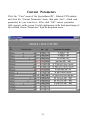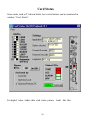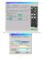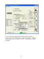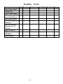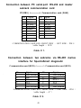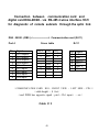
1
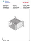
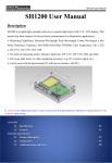
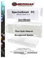
SpectraSmart PC
Software Version 6. xx
User Manual
Fiber Optic Network
Management System
Meridian Technologies, Inc.
700 Elmont Road, Elmont NY 11003
Telephone: 516. 285. 0570 Fax: 516. 285. 6300
E-mail: [email protected] Web: www.meridian-tech.com
Document Version 9.1
06/24/2015
TABLE OF CONTENTS
INTRODUCTION…………………………………………………………….
SPECTRA SMART PC – NETWORK MANAGEMENT SYSTEM….…….
SPECTRA SMART PC SYSTEM HARDWARE……………………………
MASTER SUBRACK …………………………………………………………
SLAVE SUBRACK…………………………………………………………..
SUBRACK WITH USB AND ETHERNET CONNECTION……………….
SX-PS CARD JUMPER LOCATION ……………………………………….
SX-PS CARD PINOUT DIAGRAM ……………………………………….
NETWORK……………………………………………………………………
RING/STRING……………………………………………………………….
START SPECTRASMART PC..…………………………………...…………
LOGGING ON TO SPECTRASMART PC…………………………………
AUTODETECT SUBRACKS ON NETWORK………………………………
STARTING WITH THE RACKS OR RINGS………………………..………
SETUP SUBRACKS……………………………………………..……………
CONFIGURATION……………………………………………….….……….
ETHERNET NETWORK INTERFACE - TCP / IP CONNECTION………...
HARDWARE ADDRESS…………………………………………….……….
IP ADDRESS………………………………………………………...………..
DIRECT ETHERNET CONNECTION PC TO SUBRACK ……………….
OPTIC DIAGNOSTIC INTERFACE…………………………………………
ALARM HISTORY…………………………………………………………..
LOGIN………………………………………………………………………..
SETUP CARDS, CHANNELS………………………………………..………
DATABASE OF CARDS……………………………………………..………
VIEW PINOUT OF THE CARD……………………………………..……….
CURRENT PARAMETERS…………………………………………..………
CARD MEMORY…………………………………………………….……….
CARD STATUS……………………………………………………………….
SFP MONITIRING…………………………………………………..……….
OVERVIEW…………………………………………………………..……….
SUBRACK…………………………………………………………………….
CARD………………………………………………………………………….
CHANNEL…………………………………………………………………….
ALARM HISTORY…………………………………………………………...
ALARM WINDOW…………………………………………………………..
ASCII EXPORT Of SpectraSmart ALARM CONDITIONS…………………..
COPYRIGHT INFORMATION………………………………………………
SETTING UP SPECTRASMART PC………………………………...……….
SECURITY LEVELS…………………………………………………………
RJ45 AND RJ11 PIN CONFIGURATION………………………….………..
CABLE INFO………………………………………………….……….. …….
2
3
4
5
6
7
8
10
11
12
12
12
13
14
15
16
17
18
19
19
22
25
27
29
30
32
33
34
35
36
38
40
41
42
42
43
44
44
45
45
46
47
48
INTRODUCTION to SPECTRASMART VERSIONS 6.xx
MERIDIAN TECHNOLOGIES, INC. IS PROUD TO INTRODUCE THE
WINDOWS 2000/XP/Vista/7/8A SPECTRASMART PC VERSIONS 6.xx TO USERS
WHO HAVE OPTED FOR THIS TECHNICALLY ADVANCED, LINK STATUS
MONITORING, DIAGNOSTICS AND NETWORK MANAGEMENT FEATURE.
AS WITH ANY NEW SOFTWARE BASED SYSTEM, THERE WILL BE
DIFFICULTIES ENCOUNTERED IN LEARNING HOW TO CONFIGURE AND
SET UP THE SYSTEM.
THE FACTORY IS AT YOUR DISPOSAL FOR ALL
TECHNICAL SUPPORT QUESTIONS – PLEASE CALL (516) 285-0570.
REMEMBER THAT A COMPUTER AND SOFTWARE ARE CONTROLLED BY
THE USER. SHOULD THE USER FIND THE SYSTEM IS NOT RESPONDING
PROPERLY, THE BEST PROCEDURE IS TO RESTART THE PROGRAM
FROM THE BEGINNING. WE APPRECIATE ANY FEEDBACK AND/OR
SUGGESTIONS FROM OUR CUSTOMERS AND ASK THAT YOU WORK
WITH MERIDIAN TECHNOLOGIES TO MAKE SPECTRASMART PC THE
MOST USEFUL AND PROFITABLE TOOL FOR INSTALLING FIBER
OPTIC COMMUNICATION SYSTEMS. SOFTWARE UPGRADES WILL BE
SHIPPED TO ALL OF OUR CUSTOMERS FREE OF CHARGE.
3
SPECTRASMART PC -- NETWORK MANAGEMENT SYSTEM
SpectraSmart PC is a Windows 2000/XP/Vista/7/8A based Link Status
Monitoring and Diagnostic System for Meridian Technologies’ Fiber Optic
Transmission Equipment. The hardware and firmware reside in the SR2000/S2-PC Master , SR-2001/ES2-PC Expansion 19” subracks and
Universal Subrack Frames 2,3,4,6,8 Slots. The Master connects to a host PC
via RS-232 serial port, USB or Ethernet; connects vertically to nine (9)
Expansion racks and horizontally to 10 Masters (in other racks) by daisy chaining via RS-485 using expansion ports on the front of the units. Hardware
includes controllers that are used to monitor certain critical parameters within
system cards, which are plugged into the subracks.
The PC scans card and channel parameters in sequential order, checking for
levels against factory-set threshold values. If an error condition is detected, the
PC will continue to scan through system components until the error condition
has been detected 3 times. An alarm will then be generated; the nature of which
will depend on the severity of the error condition. In order to reduce the
processing time required for partially populated subracks and limit the
reporting of constant alarms (such as a camera disconnected for maintenance),
SpectraSmart will only check those system components that have been
activated, i.e. those that have been designated as operational. For a particular
channel to be monitored, it is necessary that the particular subrack within which
the card is resident must be activated. Also, the card on which the channel is
resident must also be activated as well as the channel itself. Subracks,
individual cards or individual channels can be “turned off”, if required, in order
to reduce the number of false alarms generated.
Once an alarm occurs, it is necessary to rectify the fault that caused the alarm
and reactivate the particular card and channel affected before the system is able
to continue monitoring. If the alarm persists when the channel is reactivated,
the original fault is still present or a new fault has been detected. The fault
must be rectified before the channel can be returned to full operation.
SpectraSmart PC version 4.01 and higher can monitor and diagnose not only
subracks SR-2000 / 2001 and SR-1002/SR-1350/SR-1450/SR-1460/SR1600/SR-1850 , but self healing Ring / String with multidrop modems. The PC
4
scans Master Primary / Secondary and all Slaves in sequential order and analyze
optic link condition, shows data tracing from Master to selected Slave.
IT IS IMPORTANT TO NOTE THAT SPECTRASMART PURELY
MONITORS SYSTEM CARDS. AS LONG AS THERE IS POWER TO THE
SUBRACKS , ALL TRANSMISSION FUNCTIONS CONTROLLED BY THE
SYSTEM CARDS OPERATE INDEPENDENTLY OF THE CONDITION OF
SPECTRASMART PC.
SpectraSmart PC System Hardware
The primary component of the SpectraSmart Diagnostic System is the subrack (SR).
Subracks SR-2000/2001. The subrack is based upon industry standard 19’’
Euro rack components but has been modified in some instances to
suit operational requirements. The subrack occupies 3U of rack
space and is 277mm (10.9’’) deep and has handles which protrude
forward 40mm (1.6’’) from the mounting point.
Subracks SR-1002/1350/1450/1460/1600/1850 have a 2/3/4/4/6/8 Slots
accordingly.The chassises have many racking and mounting options,
providing a range of flexible solutions. All Meridian’s transmission
units are compatible with these racks and are manufactured with
ease of installation and can be Wall Mounted, Shelf Mounted or
Desk Mounted.
P.S.U.
The power supply units are installed into the rear of the subracks
SR-2000/2001 at the left hand side (looking from the rear). The unit
is off when the main power switch is pointing down. It is either an
100 W switched mode power supply /PS/ unit that is able to
accept mains input voltages over either 110VAC or
220/240VAC at 50/60 Hz without adjustments. The units are able
to provide sufficient power for any combination of 18 cards or up to
14 cards with PS redundancy.
The subracks SR-1xxx/S are powered by an single external switching
power supply 9V , 8,33A / Meridian model PS-60, while the SR1xxx/R chassises incorporate redundant power supplies.
System
SpectraSmart hardware is included interface and communication
5
Cards
cards for subracks SR-2000/2001 or diagnostic card for subracks SR1002/1350/1450/1460/1600/1850. The guide rail ensures that cards
can only be installed the right way up. Diagnostic card must be install
on the last Slot of the Subrack. See instruction and operation manuals
for further information on system cards.
MASTER
SUBRACK SR-2000/2001
6
SLAVE
SUBRACK
7
SR-2000/2001
SR-2000/2001 SUBRACK WITH USB AND ETHERNET CONNECTION
Interface board
Communication board :
master
slave
Interface, Master and Slave Front Panel Layout Diagram
SpectraSmart PC can work with subracks through the Ethernet or USB by using
SpectraSmart version 4.16.11 and higher. Communication board has packed into
an RJ-45 connector device server XPort comes with a 10BASE-T/100RASE-TX
Ethernet connection. Master subrack connected to Ethernet but slaves used
driver RS485 for connecting to Master subrack and to the other slaves.
Input/Output termination resistors are usually necessary for RS-485 applications.
Without proper termination, the error rate of data transmission may be high due to an
“echo” effect on the electrical connection. With the addition of a termination resistor
at the beginning or at the end of the electrical bus, this “echo” effect is greatly
reduced. The termination resistors are 120 ohm resistors are located inside the card,
J1 connector with two jumpers: position 2,3 & 4,5)
8
Communication board has J2 connector with four jumpers (or one jumper with red
arrow old reference): if install in left position (direction of arrow to front panel-old
reference) there is used Ethernet connection, opposite direction - USB, RS-232 or RS485.
Communication Board Jumper Location
J1
J2
Three parallel connector RJ-11 / 6 pins / are for drivers RS-485 /4 wires/. Pinout of RJ-11 Serial
Port is shown on the table 1. The connector RJ-45 /8 pins/ is for driver RS-232. Pinout of RJ-45
Serial Port is shown on table 2. RS-232 lines are limited to 15m (50 ft.) in length at 9600 baund,
and to 2m (6 ft.) at 115.2K bound, although they will generally work at longer lengths/cable #
1/. RS-485 lines are limited to 2000 ft.
9
System SpectraSmart is included in Diagnostic card SX-PC for subracks
SR-1002/1350/1450/1460/1600/1850-PC (look at the pictures below) they are
installed in last slot position. SpectraSmart PC can work with this Diagnostic
cards from version 6.04.xx and higher.
J1
J2
SX -PC-M Master Card
Jumper Location
The SX-PC-M Master Dignostic card has connector J2 located near Ethernet socket and
has one jumper for two positions: Ethernet (up) and USB (down). Slave Diagnostic
card doesn’t have USB and Ethernet connectors. Connector J1 with Jumpers located
near RS-485 connector and connected to termination resistors 120 ohm resistors are for
reduce “echo” effect.
10
SX -PC-M Master Card
Front Panel Layout Diagram
STATUS INDICATORS
PWR – Power (Green)
DIAG – Card Diagnostic, Power
and Temperature
Normal (Green)
Out of Range (Rred)
ROTARY SWITCHES
Subrack #
Tens
Ones
RS-485 IN/OUT (RJ-11 Female)
Port 1/2
1. Ground
2. Transmit Data- (XMT-)
3. Receive Data+ (RCV+)
4. Receive Data- (RCV-)
5. Transmit Data- (XMT+)
RR-485 STATUS INDICATORS
TX – Transmit Data (Green)
RX – Receive Data (Green)
USB STATUS INDICATORS
USB INPUT (Type B)
1. Power +5v
2. Data3. Data+
4. Ground
TX – Transmit Data (Green)
RX – Receive Data (Green)
ETHERNET STATUS
INDICATORS
ETHERNET IN/OUT (RJ-45
Female)
1. Transmit Data+ (TX+)
2. Transmit Data- (TX-)
3. Receive Data+ (RX+)
4. Receive Data- (RX-)
10/100 – Link LED:
Amber – Half Duplex
Green – Full Duplex
ETHERNET RESET
Network
11
The extension port RJ-11(RS-485) on the bottom of the front panel of the SR2000/S2-PC Master subrack enables up to 10 other Master subracks to be daisychained to the PC. In this way, all system cards within a large Network can be
monitored from the PC.
Master communication board and Diagnostic card can be used as Slave.
Ring\String
Multidrop modem can be set on three modes : Master Primary, Master
Secondary and Slave. Master has diagnostic drivers: RS-232 for connection to
PC /socket RJ-45/ and RS-485 for extension /socket RJ11/. In Slaves mode
modem does not use diagnostic drivers. Master makes diagnostic
communication with slaves through special channel of optic link. If master does
not have handshake from Spectrasmart PC program modem self diagnostic begin
to work. Master microcontroller communicates with Slaves by optic link and
shows on the own display information about parameters and status of optic link
condition.
SpectraSmart PC requires about 20 Mb of memory on your hard drive. Other
hardware requirements are:
- PIII PENTIUM 700 Mhz or better
- Windows 2000 , XP, Vista, 7, 8A
- 128 Mb SDRAM
- 1024 x 768 screen resolution
- 2MB Video Card or better
Start SpectraSmart PC
Click the Start button on Windows' taskbar and then point to Programs.
SPECTRASMART PC appears on the Program menu. Click on SpectraSmart PC.
The system always displays the copyright screen, with two buttons “ Exit “ and “
Start “.
12
Logging on to SpectraSmart PC
1. Click the "Start" button and a window appears with Logon and password
prompts .
2. If you login for the first time you should enter "admin" into Login name box and
click "OK" or press "Enter".
13
The window "Login Name List" appears. Click menu "User" and choose "New" or
4from toolbar choose "Enter New User". Enter your login name and choose the
security level into particular boxes.
Click “Apply“ and close the window or click "OK".
Click "Start" again. Login window appears. Enter your Login name and password.
If you are new user there will be prompt to enter your password for confirmation.
3. If the Password is wrong, a window appears with the message “ Try again “.
4. Click “OK” and enter your Password again.
5. You can remove any login name from the list. For security reason you can remove
‘admin’ after adding at least one Login Name with ‘sa’ or ‘manager’ level . / look table
“Security levels”/. But if this person forgets his/her password, you should uninstall the
program and install it again.
AutoDetect Subracks on network
SpectraSmart PC for Windows automatically detects Subrack(s) and Rings /
Strings on the network. The detection process starts after entering your password
. When Subracks or Ring are detected , SPECTRASMART PC adds them to the
database. A message
“ System detected N subracks. OK ? “ and three
buttons “ Yes “ , “ No “ and “Cancel” appear.
If SPECTRASMART PC has not detected any subracks, message appears “ System
doesn’t detect any subracks. OK ?”
14
1. Click “Yes", if you agree with SPECTRASMART PC and the next
window appears.
2. Click “No", if you disagree with SPECTRASMART PC and system
repeats checking network.
3. Click “Cancel”, if you want to leave SPECTRASMART PC.
SpectraSmart PC has two start options for multidrop network : Automatic
or Manual.
In Automatic mode system automatically detects slaves quantity on the
network.
In manual mode need to type the number of slaves and click “ OK ”.
This mode is very important if system start on the broken LAN /fiber line or
modem/ and system can not calculate slave quantity.
Starting with the Racks or Rings
If SPECTRASMART PC accepts your Password and you acknowledge the
quantity of subracks on the net , a screen with SPECTRASMART PC – NET
with Rack , Subracks or Rings appears. At the top right-hand corner of the
screen three color boxes appear: green - activate , blue - inactivate and red alarm status of the transmission components (subrack, card, channel or
modem). Box “Active Polling” flashes when the system is polling.
15
Menu of the window SPECTRASMART PC – NET
Setup Subracks
Click the Setup menu of the SPECTRASMART PC - NET window.
Submenu “Activate” and “Inactivate “ appears.
1. Click “Activate” and then click the mark color box near each subrack you
want to activate.
2. Click “Inactivate” and then click the mark color box near each subrack you want to
inactivate
Click “Yes” on the warning box if you confirm that you wish to inactivate a
subrack.
3. Click OK on the prompt box to finish setup.
OR
1. Click right button on the mark color box near the subrack you want to (in)activate.
2. Popup menu appears, click the desire setting.
16
Configuration
Click the Configuration menu of the SPECTRASMART PC - NET windows.
Submenus “Change port” , “Change the highest address number “ and “ Source
address” appear. If you have security level "SA" or "MANAGER", there will be
submenu "Logins"
1. Click “Change port” and select Serial Port PC “COM1” or “COM2” or
"COM3" or "COM4". Click "OK". If you don't want any changes, close the window by
clicking on the box X in the upper right corner of this window. You can open
windows “Change port” clicking “Ctlr”+” P” on the copyright screen “
SPECTRASMART PC “ .
For change baud rate click ” Ctrl + S “ , choose rate and restart system .
Firmware of interface and communication cards for baud rate 9. 6 Kb has version
4.10.
2. If you are going to connect the diagnostic computer to the SR-2000 USB port / SSPC version 4.16.10 or higher /, please following these instructions for proper
installation of the USB drivers (FTDI Virtual COM Port - VCP):
• Turn power on the Subrack and PC;
• Plug in the USB cable. This should bring up Found New Hardware Wizard;
• Insert SpectraSmart installation CD and click Next;
• Click “Search for a suitable driver for my device(recommended)”, select Next;
• Click CD-ROM drive, select Next;
• If the Wizard found the driver, click Next, then Finish.
17
• If the Wizard did not find the driver, click Back, then click “Specify a location”,
then Browse and find folder ‘Drivers’ on CD-ROM drive (usually D: or E:),
select Next;
• If the Wizard found the driver, click Next, then Finish.
If SpectraSmart had been in use previously with the RS-232 port & driver, it will
be necessary to change the Port in PC Registry. DO NOT TURN OFF THE
SUBRACK. In the computer click Start -> Settings -> Control Panel -> System
->Hardware -> Device Manager. Click + near Ports. In the list under Ports find
USB (COMX), where X is number of virtual COM Port. Usually it is COM3 or
COM4.
Start SpectraSmart PC program. When the Copyright screen appears click
“Ctrl+P”. A “Choose Port #” window will come up. Select the “X COM Port”,
captured by USB that was previously identified and click ‘OK’.
3. Click “Change the highest address number” and enter highest address number
of Subrack or String \ Ring on network. It may be a number from 0 to 29 (depend
on version).
4. Click “Source address”. Dropdown Menu appears. To enter Subrack / Modem
Location select "Subrack / Modem", then "Edit". To enter Source Address for the
channels, select "Channel", then "Edit" and in the appeared window select Subrack #
, Slot #Card name , No Channel # and write on frame Name of object and
location . Example : “ Camera # 11, Main Hall, Monitor # 7 “. Maximum quantity
of characters - 60. Click “Apply“ for storing that message into the memory.
5. Click "Logins" and a window with list of LOGIN NAMES appears. You can add
or delete login names or erase the passwords.
Ethernet Network Interface - TCP / IP connection.
SpectraSmart PC can work with subracks through the Ethernet by using SpectraSmart
version 4.17.7 and higher. Communication board and Diagnostic card have packed
into an RJ-45 connector device server XPort. Subrack should be assigned its own
public IP address and its serial port settings should be set for 38400 baud rate, 8 data
bits, 1 stop bit, no parity , Pack Control – Enable Packing and Idle Gap Time – 52
msec. It is possible to access SpectraSmart outside of the company’s LAN or the
Internet. In that case, the Network Administrator of the company where Subrack
18
physically located should be asked to open up TCP 10001 port for the inbound traffic
on the LAN’s firewall (if there is a firewall).
Hardware Address
You need to know the unit’s hardware address (also known as a MAC address). It is
on the product label, in the format: 00-20-4a-XX-XX-XX, where the XXs are unique
numbers assigned to the product /label on the cover of RJ-45 connector of the
communication board /.
IP Address
Each Master Subrack must have a unique Public IP address on your network
and number on the front panel 00, 10, 20 ... . Slaves are always designated as
01, 02..,11, 12.. 21, 22…and connected to Master by RS-485. The systems
administrator generally provides the IP address /static/, subnet mask, and
gateway. The IP address must be within a valid range, unique to your network,
and in the same subnet as your PC.
For assigning an IP address to your unit that you connect to the network use
DeviceInstaller software. Install program DeviceInstaller , click “Setup.Exe” in
folder “XPORT\ DeviceInstaller” on the CD . Respond to the installation wizard
prompts. Then open DeviceInstaller , click Start, Programs, Lantronix,
DeviceInstaller. For additional information look in CD folder XPort.
The unit’s IP address is normally set to 67.93.140.xxx at the factory.
Note: If the unit already has an IP address (e.g., DHCP has assigned
an IP address), click the Search icon and select the unit from the list of
Lantronix device servers on the local network.
• Click the Assign IP icon
• If prompted, enter the hardware address (on the product label) in the format
00-20-4a- XX-XX, where the XXs are unique numbers assigned to the product.
Click XX- Next.
• Select Assign a specific IP address and click Next.
• Enter the IP address . The Subnet mask displays automatically based on the IP
address; if desired, you may change it. On a local network, you can leave the
Default gateway blank (all zeros). Click Next.
• Click the Assign button and wait several seconds until a confirmation message
displays. Click Finish.
19
•
Select the XPort from the main window list and click Tools>Ping. The results display
in the Status area. Click the Clear Status button to clear the window so you can ping
the device again.
Note: If you do not receive “Reply” messages, make sure the unit is
properly attached to the network and that the IP address assigned is valid
for the particular network segment you are working with.
Use the Menu (buttons) on the left to navigate to sub pages where you can
configure the XPort. When you are finished, click the Update Settings button
20
to save your settings.
Note: For more information about DeviceInstaller, see the XPort User
Guide, the DeviceInstaller User Guide on the product CD and the
DeviceInstaller help file.
Click on Configuration menu of the SPECTRASMART PC - NET windows.
Submenus appear. Choose “Change port“. Window “Change port“ appears. If there is
no option “Ethernet” in the window then click Ctrl-E. Choose “Ethernet” and start
program again.
Protocol TCP/IP window appears.
Add the IP address that you assigned to communication board.
Enter Path to the local computer directory or the shared folder with Read & Write
rights (if the computer is the client on the LAN) where you want shared information
files to be stored.
Click “Yes“ and auto-discovery begins.
21
Direct Ethernet connection PC to Subrack (without Network)
Connect Master subrack # 00 to PC by Ethernet straight cable. On PC (Windows XP)
go to Start/Control Panel/Network Connection/Properties (for Windows 7 go to
Start/Control Panel/Network/View network status and tasks).
22
For Wndows 7:
Scroll down to the Internet Protocol (TCP/IP) and press Properties.
23
Configure the IP Address and Subnet Mask according to picture below then
press OK
PC is ready to communicate with SR2000 over the Ethernet cable.
The SR2000’s IP address is set to 67.93.140.105 at the factory so you don’t have to
configure it.
Note: if PC running firewall - deactivate it during the setup for the proper work of
Lantronix DeviceInstaller.
24
Optic Diagnostic Interface
SpectraSmart PC can work with remote subracks through the optic links using
digital card with RS-485 drivers 4 wires such as DXA/B- 2K/2K /channel 1/.
This is a typical configuration of diagnostic system with remote subracks in 5
different locations.
/Use cards DXB-2K/2K in central office , DXA - … in remote subracks /
25
There is a typical configuration of diagnostic system with remote subracks in
2 , 3 or more different locations using cards as DR-1W2A2G/2A2G53/51CD and DT-1W2A2G/2A2G-51/53CD or DR-2W6C1G/6C1G-49/47CD
and DT-2W6C1G/6C1G-47/49CD with RS-485 4 wires .
PC side
Remote side
Notice:
- Need to have 2 cables: in PC side – cable 4A, in Remote side – cable
4B (see cross tables on the page 41).
26
Alarm History
Click the Alarm History menu of the SPECTRASMART PC - NET windows.
Submenu “View”, “Clear“ appears.
1. Click “View” and check the table by scrolling.
2. To select rows for deleting or printing set cursor on the left most column (gray
one) of the table and click on it . To select multiple rows do the same holding
down button "Ctrl" .
3. To delete or print all or selected rows click menu or toolbar "Delete" or "Print".
Dropdown menu appears. Choose desired menu.
4. There is the possibility to filter the Alarm History table by columns : "Source
Address",
"Subrack #", "Slot #", "Card Name", "Channel", "Date" or
"Problem". Click Menu "Records", then "Select". Choose the filter then click
"OK".
27
5. To sort records of Alarm History click "Records", then "Sort" and choose up to
three columns in any order you want to sort.
6. To find record(s) click "Records", then "Find", choose what you want to find and
click "Find Next". Click "Find Next" until the message appears "Not found".
Found records will be highlighted.
28
Login
From this menu you can logout and logon with another login name.
Subrack configuration - window SPECTRASMART PC - Subrack #
If you click on the box with inside SR type written into the Rack# frame
Subrack screen appears.
Front panel of the cards shows image and position /slot number/ of the
cards installed into the subrack. Color box with slot number shows status
of the cards : green - active, blue- inactive, red - alarm. Color boxes below
subrack indicate type and status channels of the cards.
29
Setup cards, channels
Click the Setup menu of the SPECTRASMART PC - Subrack # XX
window, submenu “Cards” and “Channels“ appears.
1. Click “Cards” and click color box with card number below each card you
want to activate /inactivate/.
2. Click “Channels” and click color boxes with channel name below each card you
want to activate/inactivate/.
3. Click “OK” to finish setup.
30
OR
1. Click the colored box of the card or channel by right mouse. Popup menu
appears.
2. Choose desired submenu : "Activate" - to activate the card / channel
"Inactivate" - to inactivate the card / channel
"Pinout" - to see the card pinout (for cards only)
"Parameters" - to see the current parameters of the card
(for cards only)
"Card memory" - to read data from flash memory of the
card (for cards that have EEPROM memory)
"Card status" - to see the current status of the card (only
for special cards)
"Source address" - to enter or change the source address
from whence comes the video/audio etc. to the channel (for
channels only)
3. You can enter or change Source Address for the channel, clicking menu “Source
Address” of popup menu. Click on box of channel to see the Source Address.
31
Database of cards
Click the “View” menu of the SpectraSmart PC – Subrack # XX window
and click the “Database of cards” menu of the dropdown menu of the
window and check the table by scrolling.
32
View pinout of the card
Click the “View” menu of the SpectraSmart PC – Subrack # XX window and
click “Pinout’.
Enter slot # and click “OK”. Pinout of the card appears on the screen.
You can drag this picture with the mouse. Click “Zoom” and then
choose the desired size of the card pinout. Note: double - click on the
image of the card with right mouse can access pinout of the card also.
33
Current Parameters
Click the “View” menu of the SpectraSmart PC – Subrack # XX window
and click the “Current Parameters” menu, then enter slot # , which card
parameters do you want to see. After click “OK” current parameters
table appears on the screen. Or click right mouse on the front panel image of
the card and choose "Parameters" from the dropdown menu.
34
Card Memory
If the card has EEPROM memory , you can read the memory click right
button on the image of the card or colored box under the image and choose
"Card memory". The window "Card Memory" appears. It shows text boxes :
Part Number, Serial number, Date of Manufacture, Working days, Max
Temperature of the card .
35
Card Status
Some cards, such as T1 shown below, have extra features can be monitored in
window “Card Status”.
For digital video / audio /data card status picture looks like this.
36
Click “ More Info “, then “Data Error “ and you will see the picture, shown below.
37
SFP Monitoring
If card has Small–Form Pluggable /SFP/ optical transceiver modules with
digital diagnostic monitoring interface , “Card Status” shows picture:
This sample channel 2 has digital diagnostic for SFP but channel 1 does not.
If you click button “SFP Parameters” picture is appeared:
38
To renew parameters click “Refresh SFP parameters” button.
If cursor moved in “SFP Parameters“ table text appeared: “ If RED –
the parameter is above threshold , if BLUE – the parameter is below
threshold”.
39
Overview
SpectraSmart PC monitors the total system on 3 levels – Subrack - Card –
Channel. Any particular channel is identified initially by the subrack and then
by the card slot it is occupying. Any function that requires access to channel
configuration parameters must therefore be preceded by identifying the
subrack and card on which the specific channel is positioned.
The subrack level is the first that should be accessed in order to
identify a particular channel. Subrack parameters are always checked first
since subrack alarms are generally of a more critical mature than individual
card or channel alarms. At this level the configuration of the subrack and the
cards within the system can be examined. Sub racks can be activated or
inactivated.
1.
2.
The card - slot level is the second level that needs to be accessed
in order to identify a particular channel. Although less critical than subrack
alarms, card- slot alarms are considered more critical than individual channel
alarms.
This level allows the card - slot configuration to be viewed and also allows
card parameters to be moved in conjunction with the physical relocation of
the cards.
Card may also be activated or inactivated and a particular card within a
particular
subrack can be identified.
3.
The channel level is obviously the final level by which to identify
a particular channel. The address of the individual channel selected is
displayed and it is possible to view the status of each channel on a particular
card. Channel address can be edited and individual channels activated or
inactivated. It is also possible to select a particular channel on particular card
within any of the subracks from this menu.
40
Subrack
Up to 10 Master subracks can be installed on the system under the control of
SpectraSmart PC. The Master subrack - SR-2000 – features microcontrollers with
RS-232 and RS-485 ports. All other subracks – SR-2001/E- are designated as
Expansions and features one microcontroller with RS-485 ports. SpectraSmart
Network connection is via daisy-chaining expansion ports with the Master subrack.
Addresses are determined by an LED indicator which is set by rotary witch on the
front panel of the subrack. The addresses for the subrack should be set before they are
connected to the system and should ideally be numbered consecutively with the
Expansion connected directly to the Master being addresses as “01”. A suitable ribbon
cable to inter connect expansions is provided with each SR-2001/E. Expansions should
be connected to the Master in order - the nearest Expansion being connected first etc.
Masters are always designated as “00”, “10”, “20” etc.
The SPECTRASMART PC - NET window gives an indication of all the subracks
detected in the system and their state of activation. SpectraSmart PC automatically
recognizes the presence of any subrack connected to the Master via ribbon cable
through the expansion ports on each subrack. If a particular subrack is not present, the
entry will be “not exist”. If a subrack is present it will be shown as either “active” or
“inactive”. It is always recommended that subracks be installed with 1U air gap
between them and that forced air cooling be used within the rack cabinet. Excessive
temperature is not an immediate concern but the system has been designed to monitor
these parameters and warn of potential long term problems occurring due to excessive
component temperature.
The SPECTRASMART PC – Subrack # xx window gives a useful indication of the
configuration and activation state of all cards within a particular subrack. This screen
identifies the subrack and gives a pictorial representation of the slots with cards
installed, as if viewed from the rear of the rack. This information does not have to be
programmed into the system since SPECTRASMART PC is able to recognize the
presence of a card and its type.
In order for SpectraSmart PC to monitor each card in a subrack, the subrack itself
should be activated.
A subrack should only be inactivated during commissioning or if a subrack fault is
continuously causing alarm.
41
The SPECTRASMART PC – Subrack # XX window shows:
1. An overall view of the selected subrack from the rear showing which slots
are occupied, the type of cards within those slots and their state of activation.
2. Activate Card
Enables the activation of a particular card.
3. Inactivate Card
Enables the inactivation of a particular card.
4. Activate Channel
Enables the activation of the channel of the particular card.
5. Inactivate Channel
Enables the inactivation of the channel of the particular card.
Card
If SpectraSmart PC is to monitor the functions of a particular card, the card should
be activated. Once activated, all parameters associated with card function will
cause alarm conditions if they fall outside pre-set tolerances. Note that in order for
channel alarms to be produced, the individual channels on the card, as well as the
card itself, need to be activated.
Only in specific circumstances, when a fault cannot be repaired or when the system
is being commissioned or maintained, should a card be inactivated to stop alarms
from being reported. As soon as the fault is acknowledged and repaired or the work
on the system is completed, all cards should be reactivated. Note that SpectraSmart
PC automatically inactivates each card on which a fault occurs.
Channel
A channel is generally associated with an individual signal transmission path, so for instance
a 3-channel video receiver is considered a 3 channel card. A video and simplex data (for
PTZ) card which transmits on either 1 or 2 fibers will feature 2 channels on the SpectraSmart
PC screen. A video and duplex data will feature 3 channels on the screen. Each channel is
individually monitored for parameters appropriate to the channel’s particular function. This
information does not have to be programmed into the system since each card has a unique
P/N identifier.
42
If SpectraSmart PC is to monitor all functions of a card, individual channels
should be activated. If they are not, the scanning process bypasses the particular
channel and, if faults occur, no alarms are generated. This can cause problems if the
operator is expecting fault conditions to be reported. Equally, a card that is not
active could have a major fault that will not be apparent.
Only for specific reasons, when a fault cannot be repaired or when the system is in
the process of being commissioned or maintained, should a channel be inactivated
to prevent alarms from being continuously reported. As soon as the fault is
repaired or the work on the system is completed, all channels should be reactivated.
Note that SpectraSmart PC automatically inactivates each channel on which a fault
occurs.
The SPECTRASMART PC system allows the user to enter the unique address
/location/ to be assigned to each individual channel.
Alarm history
The Alarm History screen is an historic record of all alarms that have occurred on
the system since initialization. SpectraSmart PC checks parameters on cards in
sequence checking for variations against factory set values. Only after the card has
produced values that are out of tolerance on 3 consecutive scans is an alarm
produced. An Alarm Grid is dedicated to each alarm condition and these are
numbered consecutively in chronological order, older alarms having lower. The
data and time at which the alarm occurred, acknowledged and reinstalled is also
shown in the Grid.
Remove / Reactivate can erase this alarm and reactivate the card/channel. Note
that if the fault condition that caused the alarm still exists, the buzzer will sound
and a new alarm will be displayed. Since an alarm causes the offending channel to
be inactivated automatically, it should always be reactivated to ensure that the
particular channel continues to be monitored.
Remove w/o React this allows the Master Password holder to remove the alarm
from the system and ensure that the offending card/channel remains inactive. The
system asks for confirmation that it is acceptable. This is useful in situations when
a fault cannot be immediately rectified or if a channel is likely to be continually
producing faults during maintenance or commissioning.
43
Alarm window
The typical alarm window gives a great deal of information on the nature and
location of a particular alarm. It indicates whether the alarm is specific to a
subrack, card slot or channel and display the following details:
Source Address :
if the alarm is a channel alarm and that channel has been assigned
an address, it is displayed here.
Subrack
:
the subrack containing the fault is identified here.
Slot #
:
the card on which the fault has occurred is shown here.
Channel #
:
if the alarm is a channel alarm, the individual channel on the card is
identified here
Problem
:
the cause of the alarm is shown here
Suggestion
:
simple troubleshooting hints are displayed to enable the operator to
identify the cause or location of the fault and to take appropriate
action to rectify the problem.
ASCII export of SpectraSmart alarm conditions
This feature allows to export data of alarm conditions in ASCII format to an RS-232
COM Port of SpectraSmart PC. This ASCII information can then be shown in another
basic PC for display and analysis. Alarm message is sent to the specified COM Port, when
the alarm occurred in SpectraSmart PC.
It is supported by SpectraSmart software version 6.06.9 and higner.
If one or both PC’s don’t have RS-232 COM ports, use USB2 to RS 232 Converter /
for example Tera Grand – Premium High Speed USB 2.0 to Serial RS-232 DB-9 Converter
/. When USB to RS 232 converter is used, virtual COM Port is created, and PC, when
SpectraSmart is going be running, should be connected by standard SF cable DB9 M/F
Serial Extension Cable RS232(male to PC and female to converter. A maximum length of
this cable is 50’.
To activate this feature make the connection of PCs and run SpectraSmart program >NET window ->Configuration->Alarm Stream(ASCII) -> Settings. Set Port #, Baud Rate
- 9600bpc, Data bits – 8, Stop bits – 1, then check box “Stream Enable” to mark it, select
Header “SpS.PC”, then click “Apply”, “OK”. RS 232 create Port # in Control Panel- >
System -> Hardware->Device Manager->Port->Port#. On the basic PC, if OS is Windows
XP, open Hyper Terminal go to “Start”-> “All programs” - >”Accessories”->
”Communications”-> ”Hyper Terminal”-> ”- appears windows “New Connection – Hyper
44
terminal” and “Connection Description”. Enter a name , choose an icon and click “OK”.
Next windows “Connect to” -> select connect using Com 1, if PC has real RS-232 , or, if
converter USB-RS232 is used, find virtual COM Port number in “Control Panel”>”System”-> “Hardware”->”Device manager”->”Ports (COM&LPT”) and choose this
number in Hyperterminal, and click “OK”. Windows appears “COMx Properties “ – Port
settings: set Bits per second – 9600, Data bits – 8, Parity – None, Stop bits -1, Flow
control - None and click “OK”.
PCs with Windows 7 and higher don’t have Hyper Terminal. You can usually find a
version of Hyper Terminal on the Internet or from PC with Windows XP – one file
hypertrm.exe in C:\Program File\Windows NT and second file hypertrm.dll in
C:\Windows\System32 or from CD “Spectra Smart PC v.x.xx.x” in folder
\Hyperterminal. Copy the folder from CD to basic PC or files from PC with Windows XP
into new folder “ Hyperterminal “, and create shortcut to file hypertrm.exe.
Copyright information
The Copyright information window is the first that appears after power -up.
It shows the current date and time and also gives an indication of the version of
the system that is loaded.
Setting up SpectraSmart PC
1. Insert Setup CD-ROM in a CD-ROM drive.
2. In File Manager or Program Manager, click File, and then click Run or
on the taskbar click the start button and then click Run.
3. Type the drive letter, followed by (:) and backslash (\), and the word
setup. For example: d:\setup.
4. Follow the instructions on your screen. Click Next to continue through
the Setup process.
If you have previous version of the SpectraSmart PC you should uninstall it
before installing the new one.
45
Security levels
Permission
SA Manager
Add/Change Logins
+
+
Change Port
+
Clear Alarm History
+
Delete Selected Rows
+
from Alarm History
Print Alarm History
+
Enter/Change Source
+
Addresses
Activate/Inactivate
+
Subracks/ Cards/
Channels
Read EEPROM
+
Write to
EEPROM
Other features
+
Technician
User High User Low Guest
+
+
+
+
+
+
+
+
+
+
+
+
46
+
+
+
RJ45 Serial Port RS – 232 for Diagnostic - Pin Configuration
/ FRONT VIEW - LEFT SIDE – PIN 1 /
PIN NO.
1
Description
NOT CONNECTED
RX ( IN)
2
3
4
5
6
7
8
TX ( OUT)
DTR (IN)
ISOLATED GROUND
NOT CONNECTED
NOT CONNECTED
NOT CONNECTED
RECEIVE DATA FROM
PC
TRANSMIT DATA TO PC
DATA TERMINAL READY
Table 1
RJ11 Serial Port RS – 485 for Diagnostic - Pin Configuration
/ FRONT VIEW - LEFT SIDE – PIN 1 /
PIN NO.
3
4
5
6
Description
RCV +(IN)
RCV - (IN)
XMT+(OUT)
ISOLATED GROUND
Table 2
47
Connection between PC serial port RS-232 and master
subrack communication card
PC( DB9 ) <---------------> Communication card ( RJ45 )
Pin
1
2
3
4
5
6
7
8
9
Signal
RD (in)
TD (out)
DTR (out)
Ground
Pin
1
3
2
4
5
6
7
8
Signal
TD (out)
RD (in)
DTR(in)
Ground
/ COMMUNICATION CARD RJ45 - FRONT VIEW - LEFT SIDE – PIN 1 /
/ cable length ~ 18 ft /
Cable # 1.
Connection between two subracks via RS-485 4 wires
interface for SpectraSmart diagnostic
Communication card (RJ11) <----------> Communication card (RJ11)
Pin
1
2
3
4
5
6
Pin
1
2
3
4
5
6
Signal
GND isolated
XMT RCV +
RCV XMT +
GND isolated
Signal
GND isolated
XMT RCV +
RCV XMT +
GND isolated
/ COMMUNICATION CARD RJ11 - FRONT VIEW - LEFT SIDE – PIN 1 /
/ cable length ~ 4’’ /
Cable # 2.
48
Connection between communication card and
digital card DXA-2K/2K.. via RS-485 4 wires interface /Ch1/
for diagnostic of remote subrack through the optic link
DXA - 2K/2K ..(DB9 ) <----------------------> Communication card (RJ11)
Port 4
Pin
1
2
3
4
5
6
7
8
9
Cross table
Signal
Ch1 output+
Ch1 outputCh2 output+
Ch2 outputGround
Ch1 input+
Ch1 inputCh2 input+
Ch2 input-
Port 4
1
2
5
6
7
/ COMMUNICATION CARD
Wire
green
Red
white
black
yellow
RJ11
RJ11
3
4
6
5
2
Pin
1
2
3
4
5
6
Signal
XMT RCV +
RCV XMT +
Ground
RJ11 - FRONT VIEW - LEFT SIDE – PIN 1 /
/ cable lenght ~ 4 feet /
/ card DXB has opposite signal : pin1 – Ch1 input+ … etc /
Cable # 3
49
Connection between communication card and digital
card DT/DR – 2W6C1G / 6C1G -xD via RS-485 4 wires
interface Port 4 /Ch1 / for diagnostics of remote subracks
through the optic link.
3 ft.
DT/R-2W6C1G ..(DB9M ) <--------------> Communication card (RJ11M) - 2 cables
Port 4
Pin
1
2
3
4
5
6
7
8
9
Cross tables
Cable 4A
Signal
CH1 IN +
CH1 IN GND
CH1 OUT+
Port 4
1
4
5
6
9
RJ11M
3
4
1,6
5
2
RS-485 4W
Pin
1
2
3
4
5
6
Signal
GND
XMT RCV +
RCV XMT +
GND
Cable 4B
CH1 OUT -
Port 4
1
4
5
6
9
RJ11M
5
2
1,6
3
4
Notice:
- Need to have 2 cables: in PC side – cable 4A, in Remote side – cable
4B (see cross tables above and picture on the page 22).
- Pin 1 of the sockets RJ11 on communication card is on the left (front view).
Cables # 4A, 4B.
50
Notes:
51
Meridian Technologies, Inc
700 Elmont Road, Elmont, NY 11003, USA
Tel: 516-285-0570 Fax: 516-285-6300
E-mail: [email protected]
www.meridian-tech.com
Document Version 9.1
07/24/2015
52