1
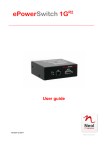
ePowerSwitch 8XS User guide Version 02 2011 www.neol.com ePowerSwitch 8XS © Copyright by NEOL S.A.S - 4 Rue Nationale, 67800 BISCHHEIM, France Printed in France All rights reserved. No part of this documentation, accompanying software or other components of the described product may be reproduced or transmitted in any form or by any means, electronic or mechanical, including photocopying and recording, for any purpose other than the personal use of the purchaser without the express written permission of NEOL S.A.S. This documentation, the ePowerSwitch 8M+R2, its peripherals, accessories and accompanying software were produced with great care, yet errors are possible. NEOL S.A.S assumes no responsibility for errors within the documentation, the hardware or the software. NEOL S.A.S reserves the right to change programs or the documentation from time to time without informing the user, errors and omissions excepted. Trademarks Neol and ePowerSwitch are registered trademarks of NEOL S.A.S. All other brand names and product names used in this book are trade names, service marks, trademarks, or registered trademarks of their respective owners. Page | 1 User Guide CONTENTS SAFETY INSTRUCTIONS: To be read before use! ...................................................................................... 3 Consignes de sécurité : à lire avant utilisation ! ............................................................................................ 4 1. DESCRIPTION .......................................................................................................................................... 5 1.1. Package list ........................................................................................................................................ 5 1.2 Compatibility tables ............................................................................................................................. 5 3. Diagram ..................................................................................................................................................... 6 3.1. Front panel ......................................................................................................................................... 6 3.2. Back .................................................................................................................................................... 7 4. Connection to a Master ............................................................................................................................. 8 5. Controlling the Satellite power outlets through the Master Web Server.................................................. 10 6. Controlling the Satellite power outlets using a Terminal Connection ...................................................... 11 6.1. Using the RS232 port ....................................................................................................................... 11 6.2. Using the RS485 port ....................................................................................................................... 11 6.3. Commands ....................................................................................................................................... 11 6.3.1. Controlling of the power outlet(s) ........................................................................................... 12 6.3.2. Reading out the power outlet status....................................................................................... 13 6.3.3. Setting of the power up delays ............................................................................................... 14 6.3.4. Reading out of the power up delay(s) .................................................................................... 14 6.3.5. Setting the restart delays ....................................................................................................... 15 6.3.6. Reading out of the restart delays ........................................................................................... 15 6.3.7. Setting the power up default status ........................................................................................ 16 6.3.8. Reading out the power up default status ............................................................................... 16 6.3.9. Reading out the switching counter values of the relays ......................................................... 17 6.3.10. Resetting the switching counter values of the relays ........................................................... 18 6.3.11. Restoring to factory settings................................................................................................. 18 Technical Data ............................................................................................................................................. 19 Statement of Conformity .............................................................................................................................. 20 Page | 2 ePowerSwitch 8XS SAFETY INSTRUCTIONS: To be read before use! NOTE • The ePowerSwitch devices can only be installed by qualified people with the following installation and use instructions. The manufacturer disclaims all responsibility in case of a bad utilization of the ePowerSwitch devices and particularly any use with equipments that may cause personal injury or material damage. • This equipment is designed to be installed on a dedicated circuit that must have a circuit breaker or fuse protection. • The electrical power sockets used to plug the power cords of the ePowerSwitch devices must be close to the ePowerSwitch devices and easily accessible. • Check that the power cords, plugs and sockets are in good condition. • The ePowerSwitch devices can only be connected to three-wire 230 VAC (50-60Hz) sockets. • Always plug the ePowerSwitch devices into properly grounded power sockets (two poles plus ground). • • Never exceed 10 Amp total load for each group of 4 power outlets of an ePowerSwitch device. The ePowerSwitch devices are intended for indoor use only. Do NOT install them in an area where excessive moisture or heat is present. • Always disconnect the 2 (two) power cords of the ePowerSwitch device if you want to intervene on the ePowerSwitch device or on the equipment powered from the ePowerSwitch device. • The power outlets of the ePowerSwitch devices are not circuit breakers! If you want to intervene on equipments connected to an ePowerSwitch device you must disconnect these equipments from the ePowerSwitch device. • Do NOT attempt to disassemble the ePowerSwitch devices, they contain potentially hazardous voltages. • The ePowerSwitch devices contain no user serviceable parts and repairs are to be performed by factory trained service personnel only. • Always use a shielded cable for the Ethernet connection. Page | 3 User Guide Consignes de sécurité : à lire avant utilisation ! Français Remarque • Les équipements ePowerSwitch ne peuvent être installés que par un personnel qualifié. Le fabricant décline toute responsabilité en cas de mauvaise utilisation des équipements ePowerSwitch et tout particulièrement en cas d’utilisation avec des équipements pouvant occasionner des blessures corporelles ou des dommages matériels. • Les équipements ePowerSwitch sont destinés à être installés sur un ou plusieurs circuits électriques dédiés protégés par des disjoncteurs ou des fusibles. Les prises secteur utilisées pour brancher les cordons secteur d’alimentation des équipements ePowerSwitch doivent être à proximité des équipements ePowerSwitch et facilement accessibles. • Vérifiez que les cordons secteur d’alimentation, les connecteurs et les prises secteur sont en bon état.Les équipements ePowerSwitch ne peuvent être connectés qu’à des prises secteur à 3 conducteurs (2 prises + terre) 230 VAC (50-60Hz). • N’utilisez que des prises secteur correctement mises à la terre (deux prises + terre) pour brancher les câbles secteur des équipements ePowerSwitch. • Ne jamais dépasser un courant total de 10 Amp pour chaque entrée secteur des équipements ePowerSwitch. • Les équipements ePowerSwitch sont destinés à une utilisation intérieure. NE les installez JAMAIS dans un endroit où règne une humidité ou une chaleur excessive. • Débranchez TOUJOURS les 2 cordons secteur d’alimentation des équipements ePowerSwitch si vous souhaitez intervenir sur les équipements ePowerSwitch ou sur les appareils alimentés au travers des équipements ePowerSwitch. • Les prises secteur des équipements ePowerSwitch ne sont PAS des coupe-circuits ! Si vous souhaitez intervenir sur les appareils alimentés au travers des équipements ePowerSwitch vous devez IMPERATIVEMENT débrancher ces appareils des équipements ePowerSwitch. • Ne démontez JAMAIS l'ePowerSwitch, il y a risque de choc électrique ! • Les équipements ePowerSwitch ne contiennent pas de pièces nécessitant une maintenance. Les éventuelles réparations ne peuvent être faites que par un personnel habilité et formé par le fabricant. • Utilisez toujours un câble blindé pour la connexion Ethernet. Page | 4 ePowerSwitch 8XS 1. DESCRIPTION ePowerSwitch 8XS is a power distribution and control unit that enables power management of 8 devices through an RS-232 or RS-485 connection. The ePowerSwitch 8XS has two separate power inputs of 10 Amp to increase the security and the load available on the power outlets. This device is intended to be connected to an ePowerSwitch Master or to the VizioGuard Environmental Monitoring Systems. Thanks to the RS232 and RS485 interfaces and its easy to use ASCII protocol, the ePowerSwitch Satellite is also the ideal solution to control power outlets through the serial connection of a KVM switch, a console server or a PC. The number of the controlled power outlets can be extended by connecting the ePowerSwitch Satellite unit to an ePowerSwitch Master 4M+, 8M+, 8M+R2, 8M+/32 or VizioGuard. 1.1. Package list The following items are included: 1 ePowerSwitch Satellite 8XS 2 power cables, 230 V / 10 Amp, length 1.80 Meter 1 RJ45 M/M, 0.50 Meter 1 serial cable SUB-D 9 points male/female, length 1.80 Meter CD including this user guide 1 quick installation guide 1.2 Compatibility tables Up to 4 ePowerSwitch 8XS Satellite from V. 2.05 can be connected to: Up to 16 ePowerSwitch 8XS Satellite from V. 2.05 can be connected to: Page | 5 ePowerSwitch M8 from V.1.1.0.0 ePowerSwitch 4M+ from V.2.1.0.0 ePowerSwitch 8M+ from V.1.0.0.3 ePowerSwitch 8M+R2 from V.2.1.0.0 ePowerSwitch 8M+/32 from V.1.0.0.0 VizioGuardTiny from V. ePowerSwitch 8XM from V.2.0.1.3 VizioGuard from V.3.0.0.1 User Guide 3. Diagram 3.1. Front panel LEDs A = Power supply A B = Power supply B 1 - 8 = Status of outlets 1 - 8 SUB-D9F Connector Terminal connection Dip Switches 1 - 4: physical address of device RJ45 Connectors xBus RS485 Cascading connection 5 - 6: xBus termination A B 1 2 3 4 5 6 7 8 (LEDs) A Green. Lights up when power applied on Group A B Green. Lights up when power applied on Group B 1 Red. Status of power outlet 1 (On/Off) 2 Red. Status of power outlet 2 (On/Off) 3 Red. Status of power outlet 3 (On/Off) 4 Red. Status of power outlet 4 (On/Off) 5 Red. Status of power outlet 5 (On/Off) 6 Red. Status of power outlet 6 (On/Off) 7 Red. Status of power outlet 7 (On/Off) 8 Red. Status of power outlet 8 (On/Off) Dip Switches 1 - 4: physical address of device 5 - 6: xBus termination RS232 (SUB-D 9F Connector) RS232 serial port with DB-9 female connector Pinout 2 = RxD 3 = TxD 5 = Gnd xBus (RS485) These connectors are used for cascading xBus devices together (ePowerSwitch Satellite, sensors, extension modules, etc.). Maximal TOTAL line length: 200 meters Page | 6 ePowerSwitch 8XS 3.2. Back Power outlets (Group B) Power outlets 5 – 8 230 VAC max 10 Amp Power input B 230 VAC – 10 Amp Page | 7 Power outlets (Group A) Power outlets 1 – 4 230 VAC max 10 Amp Power input A 230 VAC – 10 Amp User Guide 4. Connection to a Master Make sure that all the ePowerSwitch devices are powered off. Connection Instructions 1. Connect the appropriate link-up cable to one of the xBus connector of the ePowerSwitch Master and to one of the xBus connector of the ePowerSwitch 8XS. To cascade several Satellites, link the second xBus connector of a Satellite with one of the xBus connector of the next Satellite. Master unit Link-up cable to the first satellite EPS M8 RJ9M - DB9M (up to 4 Satellite units) (Réf RJ9-DB9M 180, must be ordered RJ45M - RJ45M or RJ11M - RJ45M separately) (see supplied cable set) EPS 4M+ EPS 8M+ EPS 8M+R2 VizioGuardTiny RJ45M - RJ45M (use supplied cable) (up to 4 Satellite units) RJ45M - RJ45M EPS 8XM VizioGuard RJ45M - RJ45M (use supplied cable) (up to 16 Satellite units) RJ45M - RJ45M Link-up cable to the next satellites Slct x Bus RS232 x Bus RS232 Power A B 1 2 3 4 5 6 7 8 Term Slct Power A B 1 2 3 4 5 6 7 8 10/100 A 1 2 3 4 RS232 x Bus Term Term I/O S B 5 6 7 8 1 2 3 4 Link 100 DC DRY CONTACTS MAX 24VDC - 20mA 12VDC AUX POWER SUPPLY Page | 8 ePowerSwitch 8XS 2. Allocate an address to each Satellite by positioning the address selection DIP-switches marked "Slct" on the front panel according to the following table. Remarks − Unplug the power cords of the ePowerSwitch 8XS before changing its DIP switches. − Do NOT use the same address for two different Satellites. Satellite Address DIP-Switch 1 DIP-Switch 2 DIP-Switch 3 DIP-Switch 4 1 2 3 4 5 6 7 8 9 10 11 12 13 14 15 16 Off [ON] Off [ON] Off [ON] Off [ON] Off [ON] Off [ON] Off [ON] Off [ON] Off Off [ON] [ON] Off Off [ON] [ON] Off Off [ON] [ON] Off Off [ON] [ON] Off Off Off Off [ON] [ON] [ON] [ON] Off Off Off Off [ON] [ON] [ON] [ON] Off Off Off Off Off Off Off Off [ON] [ON] [ON] [ON] [ON] [ON] [ON] [ON] Position Off = switch upwards, Position On = switch downwards DIP-Switch 1 is located on the left side DIP-Switch 5 and 6 are used to activate the built-in termination resistors. 3. On both devices located at the end of the xBus, switch the DIP-Switch 5 and 6 to ON to activate the built-in termination resistors. 4. Plug the 2 power cables into 2 grounded sockets. The A and B LEDs light on to confirm that power is on. Page | 9 User Guide 5. Controlling the Satellite power outlets through the Master Web Server Start your Web browser and type the IP address of your ePowerSwitch Master or your VizioGuard RMS system. The browser displays the authentication dialog box. Enter a user name and its corresponding password. If you log in as system administrator, you will be able to: - control individually all the power outlets and all the power outlets groups of the Master, - control all the power outlets and all the power outlet groups of the connected satellites, - display the values of all the connected environmental peripherals, - display the connection status of the I/O extension module and the status of the dry contact inputs. If you log in as a user, you will be able to: - control individually all the power outlets and all the power outlet groups for which you have the rights, - display the values of all the connected environmental peripherals for which you have the rights. The ON button allows you to switch to ON the corresponding power outlet or group of power outlets. The OFF button allows you to switch to OFF the corresponding power outlet or group of power outlets. The Restart button allows you to switch OFF the corresponding power outlet or group of power outlets. The power outlet(s) will then be automatically switched ON after the delay defined by the administrator during the configuration (default value is 10 sec). Page | 10 ePowerSwitch 8XS 6. Controlling the Satellite power outlets using a Terminal Connection The power outlets of the ePowerSwitch 8XS can be individually controlled and the status of each power outlet can be read out using a simple ASCII protocol through a serial connection. The connection can be done either using the RS232 or the RS485 port of the ePowerSwitch 8XS. 6.1. Using the RS232 port (SubD-9F connector marked RS232 on the front panel). In this case, use the supplied RS232 serial cable to connect the ePowerSwitch 8XS to an available serial port of your PC. 6.2. Using the RS485 port (RJ45 connector marked xBus on the front panel). In this case, you have to make a special serial cable (see pinout on Annexe). 6.3. Commands Run a terminal program such as Windows HyperTerminal or the MicroTerminal program on the CD (folder miscellaneous) and configure the appropriate serial port with the following settings: 9.600 bauds, 8 bits, no parity, 1 stop bit and no flow control. If you use the MicroTerminal program on the CD (folder miscellaneous) you only have to choose the used serial port, this program is already configured at 9600,n,8,1. Summary of the commands: Controlling of the Power Outlet(s) Reading out the Status of the Power Outlet(s) Ö § 6.3.1 Ö § 6.3.2 Setting the Power Up Delays Reading out of the Power Up Delays Ö § 6.3.3 Ö § 6.3.4 Setting the Restart Delays Reading out the Restart Delays Ö § 6.3.5 Ö § 6.3.6 Setting the Power Up Default Status Reading out the Power Up Default Status Ö § 6.3.7 Ö § 6.3.8 Reading out the Switching Counters of the Relays Ö § 6.3.9 Resetting the Switching Counters of the Relays Ö § 6.3.10 Restoring to Factory Settings Page | 11 Ö § 6.3.11 User Guide 6.3.1. Controlling of the power outlet(s) This command enables to control individually each power outlet or all power outlets of the same ePowerSwitch 8XS in one command. Command to be sent to the ePowerSwitch 8XS: Pxy=z[CR] Pxy=z,t1[CR] Pxy=z,t1,t2[CR] Reply from the ePowerSwitch 8XS: Pxy=z[CR] Pxy=z,t1[CR] Pxy=z,t1,t2[CR] Explanations: Parameter Value x address of the ePowerSwitch y number of the Power Outlet z command t1 delay to execute the command 1 to 16 0 1 to 8 0 1 r t 1 to 255 1 to 255 t2 restart delay Function/Remark specifies the address of the ePowerSwitch 8XS means all the power outlets specify the number of the Power Outlet set power outlet to OFF set power outlet to ON RESTART the power outlet(s) TOGGLE the power outlet(s) set the delay (in sec) to execute the command set the restart delay (in sec) If t2 is not specified, the used restart delay is the default value of the restart delay of the corresponding power outlet (see § 8.3.6) Examples: P11=1 P11=0 P35=r P30=1 P168=t P10=r,10,20 Switch power outlet #1 of ePowerSwitch #1 to On Switch power outlet #1 of ePowerSwitch #1 to Off Restart power outlet #5 of ePowerSwitch #3 Switch all power outlets of ePowerSwitch #3 to On Toggle power outlet #8 of ePowerSwitch #16 Execute the Restart Command (switch all power outlets of ePowerSwitch #1 to off) after a delay of 10 sec., then switch all power outlets to On after a delay of 20 sec. The ePowerSwitch 8XS accepts lower case and upper case commands. The ePowerSwitch 8XS sends its reply only after having received a valid command terminated by the character [CR]. Page | 12 ePowerSwitch 8XS 6.3.2. Reading out the power outlet status This command enables to read out the status of each power outlet. Command to be sent to the ePowerSwitch 8XS: Rxy[CR] Reply from the ePowerSwitch 8XS: Rxy=z[CR] Explanations: Parameter Value Function/Remark x address of the ePowerSwitch 1 to 16 specifies the address of the ePowerSwitch 8XS y number of the Power Outlet 1 to 8 specify the number of the power outlet z status 0 1 status of the corresponding power outlet is OFF status of the corresponding power outlet is ON Examples: R11[CR] Read status of the power outlets #1 of ePowerSwitch #1 R168[CR] Read status of the power outlets #8 of ePowerSwitch #16 The ePowerSwitch 8XS accepts lower case and upper case commands. The ePowerSwitch 8XS sends its reply only after having received a valid command terminated by the character [CR]. Page | 13 User Guide 6.3.3. Setting of the power up delays This command enables to set the Power Up Delay individually for each power outlet. The Delay value can be between 1 and 255 seconds (4 min 15 sec). Command to be sent to the ePowerSwitch 8XS: TUxy=z[CR] Reply from the ePowerSwitch 8XS: TUxy=z[CR] Explanations: Parameter Value Function/Remark x address of the ePowerSwitch 1 to 16 specifies the number of the ePowerSwitch 8XS y number of the power outlet 1 to 8 specifies the number of the power outlet z timer value 1 to 255 set the power up delay (in sec) Examples: TU12=2 Set power up delay of the power outlet #2 of ePowerSwitch #1 to 2 sec T163=10 Set power up delay of the power outlet #3 of ePowerSwitch #16 to 10 sec The ePowerSwitch 8XS accepts lower case and upper case commands. The ePowerSwitch 8XS sends its reply only after having received a valid command terminated by the character [CR]. 6.3.4. Reading out of the power up delay(s) This command enables to read out the power up delay individually for each power outlet. Command to be sent to the ePowerSwitch 8XS: TUxy[CR] Reply from the ePowerSwitch 8XS: TUxy=z[CR] Explanations: Parameter Value Function/Remark x address of the ePowerSwitch 1 to 16 specifies the number of the ePowerSwitch 8XS y number of the Power Outlet 1 to 8 specifies the number of the power outlet z timer value 1 to 255 shows the power up delay (in sec) The ePowerSwitch 8XS accepts lower case and upper case commands. The ePowerSwitch 8XS sends its reply only after having received a valid command terminated by the character [CR]. Page | 14 ePowerSwitch 8XS 6.3.5. Setting the restart delays This command enables to set the Restart Delay individually for each Power Outlet. The Delay value can be between 1 and 255 seconds (4 min 15 sec). Command to be sent to the ePowerSwitch 8XS: TRxy=z[CR] Reply from the ePowerSwitch 8XS: TRxy=z[CR] Explanations: Parameter Value Function/Remark x address of the ePowerSwitch 1 to 16 specifies the address of the ePowerSwitch 8XS y number of the Power Outlet 1 to 8 specifies the number of the Power Outlet z timer value 1 to 255 set the Restart Delay (in sec) Examples: TR31=17 Set Restart Delay of the Power Outlet #1 of ePowerSwitch #3 to 17 sec The ePowerSwitch 8XS accepts lower case and upper case commands. The ePowerSwitch 8XS sends its reply only after having received a valid command terminated by the character [CR]. 6.3.6. Reading out of the restart delays This command enables to read out the restart delay individually for each power outlet. Command to be sent to the ePowerSwitch 8XS: TRxy[CR] Reply from the ePowerSwitch 8XS: TRxy=z[CR] Explanations: Parameter Value Function/Remark x address of the ePowerSwitch 1 to 16 specifies the address of the ePowerSwitch 8XS y number of the Power Outlet 1 to 8 specifies the number of the Power Outlet z timer value 1 to 255 shows the Restart Delay (in sec) The ePowerSwitch 8XS accepts lower case and upper case commands. The ePowerSwitch 8XS sends its reply only after having received a valid command terminated by the character [CR]. Page | 15 User Guide 6.3.7. Setting the power up default status This command enables to set the power up default status individually for each power outlet. Settings can be "always On", "Always Off" or "Last memorized Status" before power failure. Command to be sent to the ePowerSwitch 8XS: DPxy=z[CR] Reply from the ePowerSwitch 8XS: DPxy=z[CR] Explanations: Parameter x y address of the ePowerSwitch number of the Power Outlet z default status after Power up Value 1 to 16 1 to 8 ON OFF LAST Function/Remark specifies the number of the ePowerSwitch 8XS specifies the number of the power Outlet set power up default status of the power outlet to ON set power up default status of the power outlet to OFF set power up default status of the power outlet to last memorized status Examples: DP37=LAST Set Power Up Default Status of the Power Outlet #7 of ePowerSwitch #3 to last memorized status DP165=OFF Set Power Up Default Status of the Power Outlet #5 of ePowerSwitch #16 to OFF The ePowerSwitch 8XS accepts lower case and upper case commands. The ePowerSwitch 8XS sends its reply only after having received a valid command terminated by the character [CR]. 6.3.8. Reading out the power up default status This command enables to read out the power up default status individually for each power outlet. Command to be sent to the ePowerSwitch 8XS: DPxy[CR] Reply from the ePowerSwitch 8XS: DPxy=z[CR] Explanations: Parameter x y address of the ePowerSwitch number of the Power Outlet z default status after Power up Value 1 to 16 1 to 8 ON OFF LAST Function/Remark specifies the address of the ePowerSwitch 8XS specifies the number of the power outlet power up default status of the power outlet is ON power up default status of the power outlet is OFF power up default status of the power outlet is last memorized status The ePowerSwitch 8XS accepts lower case and upper case commands. The ePowerSwitch 8XS sends its reply only after having received a valid command terminated by the character [CR]. Page | 16 ePowerSwitch 8XS 6.3.9. Reading out the switching counter values of the relays This command enables to read out the number of power up cycles of the ePowerSwitch 8XS and the number of switching cycles (Off to On) of each power outlet. Command to be sent to the ePowerSwitch 8XS: Cxy[CR] Reply from the ePowerSwitch 8XS: Cxy=z[CR] Explanations: Parameter x address of the ePowerSwitch y counter z counter value Value Function/Remark 1 to 16 0 specifies the address of the ePowerSwitch 8XS reads the number of power up cycles of the ePowerSwitch 8XS specifies the number of the Power Outlet switching counter shows the number of power up or switching cycles of the selected Power Outlet 1 to 8 The ePowerSwitch 8XS accepts lower case and upper case commands. The ePowerSwitch 8XS sends its reply only after having received a valid command terminated by the character [CR]. Page | 17 User Guide 6.3.10. Resetting the switching counter values of the relays This command enables to reset the switching counter values of the Relays. Command to be sent to the ePowerSwitch 8XS: /RC[CR] Reply from the ePowerSwitch 8XS: No reply The ePowerSwitch 8XS accepts lower case and upper case commands. The ePowerSwitch 8XS sends its reply only after having received a valid command terminated by the character [CR]. 6.3.11. Restoring to factory settings This command enables to restore all factory settings. Command to be sent to the ePowerSwitch 8XS: /FS[CR] Reply from the ePowerSwitch 8XS: No reply The ePowerSwitch 8XS accepts lower case and upper case commands. The ePowerSwitch 8XS sends its reply only after having received a valid command terminated by the character [CR]. Page | 18 ePowerSwitch 8XS Technical Data Network connection Max. network cable length Serial connection Connection Bus Nominal input voltage Input power outlet Output voltage Output power outlet Maximum total current LEDs Operating temperature Operating humidity Dimensions (LxDxH) Weight Approvals Page | 19 RJ-45 connector for UTP CAT5 100 meters (not included) RS232, SUB-D 9 female RS-485, RJ-45 230 V/50Hz IEC-320 230 V/50Hz IEC-320 2 x 10 A 1 for power supply A 1 for power supply B 8 for the power outlets status 0°C to +40°C 10% to 80% 437 x 107 x 42 mm 2 kg CE, EN 60950-1, EN 55022, EN 55024, RoHS User Guide Statement of Conformity STATEMENT OF CONFORMITY NEOL S.A.S. declares that this equipment is in compliance with the Electromagnetic Compatibility Directive and the Low Voltage Directive: Application of Council Directives: 2004/108/EEC Standards to Which Conformity declared: EN 60950-1, EN 55022, EN 55024 Manufacturer's Name and Address: NEOL S.A.S. 4 Rue Nationale 67800 BISCHHEIM -FRANCE Type of Equipment: Power Control Unit Type Designation: ePowerSwitch 8XS Satellite Reference: EPS 8XS Years of Manufacture: 2010 -2011 We, the undersigned, hereby declare that the equipment specified above conforms to the above directives. Bischheim, 1st February 2011 Paul REYSER, General Manager NEOL S.A.S. All modifications reserved EPS 8XS User Guide 2011 02.docx Page | 20