1
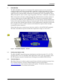
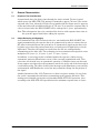
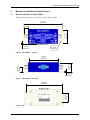
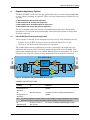
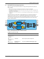
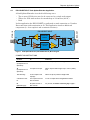
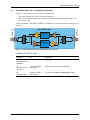
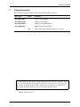
ESI-1553RPT
MIL-STD-1553/1760
Bus Repeater
User’s Manual
311 Meacham Ave ♦ Elmont
e-mail: [email protected]
♦
NY 11003
♦
tel. (516) 327-0000 ♦ fax (516) 327-4645
website: www.mil-1553.com
Copyright © 2004 – 2012 Excalibur Systems. All Rights Reserved.
Table of Contents
Table of Contents
Introduction . . . . . . . . . . . . . . . . . . . . . . . . . . . . . . . . . . . . . . . . . . . . . . . . . . . . . . . . . . .4
Unidirectional Option (-002) . . . . . . . . . . . . . . . . . . . . . . . . . . . . . . . . . . . . . . . . . . . . . . . . . . . . . . . . . 4
Technical Support . . . . . . . . . . . . . . . . . . . . . . . . . . . . . . . . . . . . . . . . . . . . . . . . . . . . . . . . . . . . . . . . . 4
General Characteristics . . . . . . . . . . . . . . . . . . . . . . . . . . . . . . . . . . . . . . . . . . . . . . . . .5
Response Time Consideration . . . . . . . . . . . . . . . . . . . . . . . . . . . . . . . . . . . . . . . . . . . . . . . . . . . . . . . 5
Output Reshaping and Symmetry . . . . . . . . . . . . . . . . . . . . . . . . . . . . . . . . . . . . . . . . . . . . . . . . . . . . 5
Mechanical and Electrical Specifications . . . . . . . . . . . . . . . . . . . . . . . . . . . . . . . . . . .6
Mechanical Outline of the ESI-1553RPT . . . . . . . . . . . . . . . . . . . . . . . . . . . . . . . . . . . . . . . . . . . . . . . 6
Connectors . . . . . . . . . . . . . . . . . . . . . . . . . . . . . . . . . . . . . . . . . . . . . . . . . . . . . . . . . . . . . . . . . . . . . . . 7
Power Requirements . . . . . . . . . . . . . . . . . . . . . . . . . . . . . . . . . . . . . . . . . . . . . . . . . . . . . . . . . . . . . . . 7
Weight . . . . . . . . . . . . . . . . . . . . . . . . . . . . . . . . . . . . . . . . . . . . . . . . . . . . . . . . . . . . . . . . . . . . . . . . . . . 7
Repeater Application Options . . . . . . . . . . . . . . . . . . . . . . . . . . . . . . . . . . . . . . . . . . . .8
ESI-1553RPT-BUS: Bus Repeater Application . . . . . . . . . . . . . . . . . . . . . . . . . . . . . . . . . . . . . . . . . . 8
ESI-1553RPT-STUB: Stub Repeater Application. . . . . . . . . . . . . . . . . . . . . . . . . . . . . . . . . . . . . . . . . 9
ESI-1553RPT-SPLIT: Stub Splitter/Extender Application. . . . . . . . . . . . . . . . . . . . . . . . . . . . . . . . . 10
ESI-1553RPT-S2S: Stub to Stub Repeater Application . . . . . . . . . . . . . . . . . . . . . . . . . . . . . . . . . . 11
Ordering Information. . . . . . . . . . . . . . . . . . . . . . . . . . . . . . . . . . . . . . . . . . . . . . . . . . .12
ESI-1553RPT: User’s Manual
page 3
Introduction
1
Introduction
The ESI-1553RPT repeater was developed for customers who need to extend the
existing length of their bus or provide the capability to utilize long stubs or to connect
a number of devices to a single stub. The repeater was implemented using simple
signal detection and switching techniques to minimize the delay through the device.
Delay through the unit is in the range of typically of 700 nsec. to 900 nsec. maximum.
Each connection to the bus is made through the implementation of a bus coupler in
various configurations. Standard MIL-STD-1553 transceivers and digital signal
processing are utilized to steer and shape the received signals, and retransmit them
in the correct direction. Each of the two connections (J1 and J2) is bi-directional. Its
type of connection is defined specifically in each configuration as marked on top of the
box. A signal received at either connector will enable the signal to flow through
towards the other connector.
P1 provides the power connection to the device which is 12-36 VDC (28V nominal).
The unit is intended to operate within the temperature range of -40º to 85º C.
Figure 1 ESI-1553RPT Repeater – 3D View
1.1
Unidirectional Option (-002)
The ESI-1553RPT-xxxx-002 repeater implements one direction only, J1 to J2. The
opposite path, J2 to J1, is blocked. This application can be used, for example, when
the RT responses must be blocked from reaching the main MIL-STD-1553 bus.
1.2
Technical Support
Excalibur Systems is ready to assist you with any technical questions you may have.
For technical support, see the Technical Support section of our website:
www.mil-1553.com. You can also contact us by phone. To find the location nearest
you, see the Contact Us section of our website.
page 4
Excalibur Systems
General Characteristics
2
General Characteristics
2.1
Response Time Consideration
As mentioned above the delay time through the unit is around 700 nsec typical,
which causes the MIL-STD-1553 message Command to appear 700 nsec later on the
repeated side. Now, when the 1553 devices responds with its Status word, it appears
on the main bus with an additional delay of 700 nsec. So in total the response time of
a device located after the ESI-1553RPT will be enlarged by 1.4 µsec. approximately.
Note This enlargement has to be considered for devices with response times close to
the system’s upper limit before adding the repeater.
2.2
Output Reshaping and Symmetry
As a limitation of the 1553 Transceiver device, used within the ESI-1553RPT, the
signal transmitted by the repeater has to be symmetrical in order to ensure that no
DC offset is introduced onto the system bus. A symmetrical signal means that each
bi-phase sync or data bit pattern must have an equal period of high & low or low &
high times. Therefore the signals received from one side are reshaped before
transmitting to the other side. The reshaping circuit reconstructs the signals in exact
multiples of 0.5 µsec. (i.e. 0.5 µsec., 1 µsec., 1.5 µsec., 2 µsec.).
In addition, a correcting circuit is included within the repeater, which corrects
asymmetric patterns (Manchester errors) of the currently transmitted word. This
correction is activated once an asymmetric quantity of 4 half bit times was detected.
It may appear anywhere after the asymmetry started or at the end of the last word in
a continuous string. The effect of this is that messages with Manchester errors will be
retransmitted with Manchester errors but may somewhat change the bit pattern of
the signal.
Another limitation of the 1553 Transceiver is that it requires waiting 1.3 µsec from
the end of a transmitted word before transmitting in the opposite direction. This
waiting period should not interfere with standard MIL-STD-1553 operation, since
according to the MIL-STD-1553 specification the minimum response time is 2 µsec.
ESI-1553RPT: User’s Manual
page 5
Mechanical and Electrical Specifications
3
Mechanical and Electrical Specifications
3.1
Mechanical Outline of the ESI-1553RPT
All measurements have a tolerance of ±0.1 mm (0.004").
(4.724")
120.0 mm
(1.772")
45.0 mm
(0.492")
12.5 mm
(0.177")
Ø 4.5 mm
4 Places
(0.142")
3.6 mm
Figure 2 ESI-1553RPT – Top View
(0.591")
15.0 mm
(1.063")
27.0 mm
(3.543")
90.0 mm
(0.098")
2.5 mm
Figure 3 ESI-1553RPT – Side View
(1.142")
29.0 mm
(4.370")
111.0 mm
Figure 4 ESI-1553RPT – Bottom View
page 6
Excalibur Systems
Mechanical and Electrical Specifications
3.2
Connectors
BUS CONNECTORS [J1 AND J2]
The J1 and J2 connectors are Trompeter BJ77 or equivalent. The connector’s pin
assignments are:
Pin Name
Signal Name
Description
CENTER PIN
BUS_Hi
MIL-STD-1553 bus high connection
INNER SHEATH
BUS_Lo
MIL-STD-1553 bus low connection
BODY
ASSEMBLY
SHIELD
Cable shield connection
Connectors J1 and J2 mate with a Trompeter PL75 connector or equivalent (not
included).
POWER CONNECTOR [P1]
The P1 connector is DB9 male connector. The P/N is CONEC 163A11319X. The
connector’s pin assignments are:
Pin #
Signal Name
Description
1
PWR+
DC power source ‘+’
3
PWR-
DC power source ‘-’
5
SHIELD
Case connection
Connector P1 mates with a standard DB9 female connector. A DB9 female connector
and a plastic hood are included.
3.3
Power Requirements
The power requirements for the repeater are:
•
•
3.4
Voltage: 28VDC nominal (12–36VDC).
Power: 4.0 Watts maximum at full loading
and 100% duty cycle. In a typical application with 50% duty cycle, the power consumption is approximately 2.5 Watts.
Weight
The unit weighs 175 grams.
ESI-1553RPT: User’s Manual
page 7
Repeater Application Options
4
Repeater Application Options
The ESI-1553RPT can be used for any application where increased signal amplitude
or wave shape reforming is required. There are four configurations available for the
repeater:
4.1 ESI-1553RPT-BUS: Bus Repeater Application
4.2 ESI-1553RPT-STUB: Stub Repeater Application
4.3 ESI-1553RPT-SPLIT: Stub Splitter/Extender Application
4.4 ESI-1553RPT-S2S: Stub to Stub Repeater Application
The key to making either an existing, or modified bus architecture functionally
operational, is to test the design thoroughly. This would also include a design that
includes a repeater.
4.1
ESI-1553RPT-BUS: Bus Repeater Application
A bus repeater is needed if your design meets one or more of the following criteria:
•
•
If there are many RTs on the bus and as a result the signal level is low.
The bus is 100 meters long and needs to be extended.
TX
RESHAPING
CIRCUIT
RX
J2
78 Ω
J1
BUS - OUT
ESI-1553RPT-BUS
78 Ω
BUS - IN
The standard bus repeater application is used to extend the bus length up to an
additional 100 meters (300 ft.) from the maximum specified in the standard. This
application assumes the bus is cut and an additional bus section added. The remote
terminals can either be existing or new equipment that are added or relocated.
RX
RESHAPING
CIRCUIT
TX
Figure 5 Bus Repeater (ESI-1553RPT-BUS) Block Diagram
CONNECTION INSTRUCTIONS
Connect
To
Comment
J1
(Trompeter BJ77 or
equivalent)
End of existing bus
Termination resistor is already included within the
repeater
J2
(Trompeter BJ77 or
equivalent)
New bus extension
Termination resistor is already included within the
repeater
Note
The new bus extension should be maximum 100 m. (300 ft.) in length and includes all the couplers
required to connect the various 1553 devices with a termination resistor at the other end.
P1
(DB9 male type)
page 8
DC power source of
28V nominal
For pinouts, see Power Connector [P1] on page 7
Excalibur Systems
Repeater Application Options
4.2
ESI-1553RPT-STUB: Stub Repeater Application
There are many factors that determine if a longer than specified stub will work.
These include:
•
•
•
How heavily the bus is loaded (total number of remote terminals).
Proximity to the Bus Controller (the closer the stub is to the BC, the higher the
probability of operating).
Architecture of the bus (whether it was designed utilizing lumped or distributed
couplers).
TX
RESHAPING
CIRCUIT
RX
J2
RX
RESHAPING
CIRCUIT
TX
78 Ω
J1
STUB - OUT
ESI-1553RPT-STUB
78 Ω
STUB - IN
The Stub repeater is used where a stub length has to be excessively long due to
routing or the need to locate it a considerable length from the bus connection.
Although the specification states that the maximum length of a stub is 20 feet it is
not necessarily assumed that by exceeding this length that all such connections
require a stub repeater.
1.14 : 1
Figure 6 Stub Repeater (ESI-1553RPT-STUB) Block Diagram
CONNECTION INSTRUCTIONS
Connect
To
Comment
J1
(Trompeter BJ77 or
equivalent)
Available stub output
With a 6m (20 ft.) maximum length cable
J2
(Trompeter BJ77 or
equivalent)
1553 device
With a 6m (20 ft.) maximum length cable
P1
(DB9 male type)
DC power source of
28V nominal
For pinouts, see Power Connector [P1] on page 7
ESI-1553RPT: User’s Manual
page 9
Repeater Application Options
4.3
ESI-1553RPT-SPLIT: Stub Splitter/Extender Application
A Stub Splitter/Extender is needed in following cases:
•
•
•
Two or more 1553 devices need to be connected to a single stub output.
Where the 1553 stub needs to be extended up to 100 meters (300 ft.)
Both
TX
J1
RESHAPING
CIRCUIT
RX
J2
BUS - OUT
ESI-1553RPT-SPLIT
78 Ω
STUB - IN
In this application the ESI-1553RPT is configured as stub connection at J1 and as
Bus connection with termination at J2. This application involves additional
components (i.e. bus coupler/s and termination resistor).
RX
RESHAPING
CIRCUIT
TX
Figure 7 Stub Splitter/Extender (ESI-1553RPT-SPLIT) Block Diagram
CONNECTION INSTRUCTIONS
page 10
Connect
To
Comment
J1
(Trompeter BJ77 or
equivalent)
Available stub output
With a 6m (20 ft.) maximum length cable
J2
(Trompeter BJ77 or
equivalent)
A coupler’s bus input
With a required cable length of up to 100 m. (300 ft.)
max.
1553 device(s)
To the coupler’s stub
output(s)
With a 6m (20 ft.) maximum length cable
A terminator resistor
The coupler’s second
bus connection
Or use a coupler with an integrated termination
P1
(DB9 male type)
DC power source of
28V nominal
For pinouts, see Power Connector [P1] on page 7
Excalibur Systems
Repeater Application Options
4.4
ESI-1553RPT-S2S: Stub to Stub Repeater Application
A stub to stub repeater is needed in following cases:
•
•
Two stub outputs need to be connected together.
Bus A stub output needs to be connected temporarily to Bus B stub output for
diagnostic tests.
ESI-1553RPT-S2S
TX
J1
RX
RESHAPING
CIRCUIT
RESHAPING
CIRCUIT
RX
STUB - IN
STUB - IN
In this application the ESI-1553RPT is configured as stub input both connections, J1
and J2.
J2
TX
Figure 8 Stub to Stub Repeater (ESI-1553RPT-S2S) Block Diagram
CONNECTION INSTRUCTIONS
Connect
To
Comment
J1
(Trompeter BJ77 or
equivalent)
Available stub output
With a 6m (20 ft.) maximum length cable
J2
(Trompeter BJ77 or
equivalent)
A second available
stub output
With a 6m (20 ft.) maximum length cable
P1
(DB9 male type)
DC power source of
28V nominal
For pinouts, see Power Connector [P1] on page 7
ESI-1553RPT: User’s Manual
page 11
Ordering Information
5
Ordering Information
Use the following part numbers when ordering the bus repeater:
Basic Part #
Option
Description
ESI-1553RPT-BUS
Single bus, bus repeater
ESI-1553RPT-STUB
Single bus, stub repeater
ESI-1553RPT-SPLIT
Single bus, stub splitter/extender
ESI-1553RPT-S2S
Single bus, stub to stub repeater
-002
Same as above with unidirectional option, J1 to J2 only
The information contained in this document is believed to be accurate. However, no responsibility is assumed by Excalibur Systems, Inc. for its use and
no license or rights are granted by implication or otherwise in connection
therewith. Specifications are subject to change without notice.
January 2012, Rev A-3
page 12
Excalibur Systems