1
User’s Manual Series DRF
2-INSTALLATION____________________________________________
Before installing the instrument check the
characteristics label attached to the side of
the unit. Specially check that the value of
the power supply needed, matches the power
supply available on your installation.
The characteristics label also indicates the
input/output signal relation for the instrument.
Remember to take note of the new input/
output relation if you proceed to readjust the
instrument.
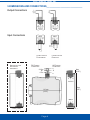
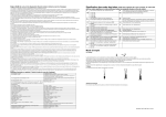
The instrument must be installed in such a
way that it remains in vertical position as
indicated on Figure4.
To help dissipate the heat, a free space of
2mm must be left available on both sides of
the instrument.
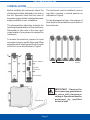
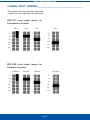
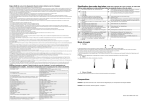
To access the selection jumpers for input
and output ranges, and the Span and Offset
potentiometers, slightly press the A-A points
of the front cover as indicated on Figure1.
J1
J2
J3
J4
J5
J6
OUTPUT JUMPERS
2 mm
FIGURE 4
POT. SPAN
POT. OFFSET
J7
J8
J9
J10
J11
J12
INPUT JUMPERS
FIGURE 2
FIGURE 1
FRONT COVER
FIGURE 3
Page 5
IMPORTANT - Opening the
front cover may grant access
to areas with dangerous
voltages. Operations must be
performed by qualified
technical staff.