1
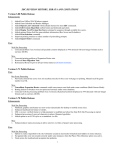
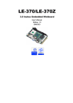
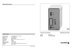
Specifications General Specifications Embedded CPU + Chipset : ZFx86 Failsafe 586 32-bit CPU core operating at 133, 100, 66 and 33 MHz with 32-bit 33MHz PCI rev 2.1 compliant Northbridge and Southbridge FailSafe internal Boot ROM that allows execution of multiple instruction sets: DRAM clear, Flash erase, executable load and run, Provides permanent and fail-safe mechanism External BIOS : Phoenix Embedded PC BIOS with RS-232 console redirection for headless BIOS access DRAM Memory : 32 MB Synchronous DRAM on board Bus Interfaces : ISA bus - 8.3 MHz (PC/104) PCI 32 bit 33MHz rev. 2.1 compliant (internal) Enhanced IDE : supports two ports and up to four ATAPI devices with Ultra DMA (ATA-4) support two 44-pin IDE connector for 2.5" (laptop-size) HDD/Flash IDE drive including power Watchdog Timer : Embedded application Dual Watchdog Timer (WDT) with SW and HW control of the WDT event 16 bit counter primary watchdog connected to SW IRQ/NMI/SMI reset by Watch Dog Timer Input (WDI). Second 8 bit counter output connected to H/W reset line enabled by primary counter output Real-time Clock : Built-in chipset with lithium battery backup for 10 years of data retention. Digital I/O : 16-bit GPIO, 8 independent GPI and 8 independent GPO programamble by software. Dual Network Controller Chipset : Dual RTL8139C, 10/100 Mbps, autoswitching Connector : two 10-pin onboard headers High Speed Multi I/O Serial Ports : three high speed RS-232C ports (COM1/3/4) and one jumper selectable RS-232C/422/485 (COM2) with 16C550 compatible UART and 16 byte FIFO, all provide jumper selecable +5V/+12V DC power USB : 2 ports USB 1.1 and OpenHCL compl. Floppy Disk Drive Interface : supports ome 3‰" floppy disk drive Bi-directional Parallel Port : supports SPP, EPP and ECP mode.BIOS enabled/disabled Keyboard and Mouse Connectors : onboard 10-pin mini header for AT Keyboard and PS2 Mouse EmCORE-i411 User's Manual 1 Inside the ZFx86 Chip Inside the ZFx86™ Chip 32-BIT X86 Processor, FPU, 8K L1 WB Cache 4-256 MB SDRAM SELECTABLE 16/32 BIT BUS NORTH BRIDGE Full PCI Bus SOUTH BRIDGE ZF FAILSAVE Boot ROM (12K Byte Update ROM) Full ISA Bus 2 USB Devices 2 EIDE Devices Floppy Disk Parallel Port 2 Serial Ports IrDA PS2 Keyboard PS2 Mouse Real-time Clock I²C Bus 8 GPIO DMA IRQ ZF LOGIC Z-tag Interface External Memory & IO Decode Logic Watchdog Timer Scratch Registers PWM Generator Flash Disk DiskOnChipfi2000 Package : Single Chip Flash Disk in 32-pin DIP JEDEC SSD Interface SSD Type : One compact flash Socket supports Type I/II Compact flash Cards (CFC) VGA Interface Chipset : SMI SM712G4AA LynxEM4+ 33 MHz PCI bus with 4 MB memory on dye Display Type : CRT, TFT, DSTN, VGA, VGA, SVGA, XGA and SXGA Environmental and Power Power Requirements : based on 32 MB DRAM and 8 MB Flash disk 33 Mhz -> 5 V @ 0.9 A 66 Mhz -> 5 V @ 0.95 A 100 Mhz -> 5 V @ 1 A (default) 133 Mhz -> 5 V @ 1.2 A (over-clocked) Board Dimensions : 145 x 102 mm. Board Weight : 0.24 Kg Operating Temperature : 0 to 60°C (32 to 140°F) OS Compatibility : Linux, DOS, VxWorks, many RTOS, Windows CE, Windows 9x, and Windows NT 2 EmCORE-i411 User's Manual Warning Single Board Computers and Miniboards contain very delicate Integrated Circuits (IC). To protect these components against damage from static electricity, always follow the following precautions when handling them : 1. Disconnect your board from the power source when you want to work on the inside 2. Hold the board by the edges and try not to touch the IC chips, leads or circuitry 3. Use a grounded wrist strap when handling computer components. 4. Place the board on a grounded antistatic pad or on the bag that came with the it, whenever it is separated from the system. Ordering Codes EmCORE-i411DVL2: 3‰" Embedded ZFx86 Miniboard with Flat Panel Display Controller, Dual Ethernet, DiskOnChip socket and CompactFlash socket (includes 32 MB onboard SDRAM) EmCORE-i411 User's Manual 3 Product Image 4 EmCORE-i411 User's Manual Dimensions EmCORE-i411 with passive cooling element EmCORE-i411 User's Manual 5 Board Layout Front PWR2 JP1 JP6 EmCORE-i411 REV : 1.0 DiskOnChip 2000 JIDE1 JIDE2 JDIO1 JIR1 JV1 ~ JV8 JLPT1 JCOM4 JCOM3 CMOS1 JCOM2 JCOM1 JP7 JKBMS1 LINUX DEVICES 14.318 MachZ™ X86 PC FailSafe JP4 JFDD1 JP5 JVGA1 JLCD1 LAN-LED JLAN2 TQ25.000 LynxEM4+ RTL8319 JLAN1 JINV1 Realtek JFRT1 JV9 1 2 3 4 ON SW1 PWR1 6 EmCORE-i411 User's Manual Jumper/Connector Quick Reference Jumpers JP6 1-2 on off on off CPU Clock select 3-4 on -> 33 MHz on -> 66 MHz off -> 133 Mhz off -> 100 MHz JP7 on off CPU Core select -> 2.7 -> D8000h CMOS1 RTC/CMOS Operation 1-2 -> Normal Operation 2-3 -> Clear CMOS JP1 1-2 2-3 3-4 COM2 -> -> -> Mode Select RS-232 RS-485 RS-422 JV8 1-2 2-3 COM1 Pin 1 Voltage -> RS-232 signal DCD# -> 5 V JP4 on off CF Card Select -> Master -> Slave JP5 1-2 2-3 LAN Enable/Disable on off LAN1 enabled LAN1 disabled LAN2 enabled LAN1 disabled JV9 1-2 2-3 LCD Voltage -> 5 V -> 3.3 V Connectors IDE1 Primary IDE (44-pin) IDE2 Secondary IDE (44-pin) JFDD1 FDD interface JCOM1 COM 1 (RS-232) JCOM2 COM 2 (RS-232) JCOM3 COM 3 (RS-232) COM 4 (RS-232) JKBMS1 Keyboard/Mouse JV7 1-2 2-3 COM1 Pin 9 Voltage -> RS-232 signal RI# -> 12 V JCOM4 JLPT1 Primary Parallel Port JV6 1-2 2-3 COM2 Pin 1 Voltage -> RS-232 signal DCD# -> 5 V JVGA1 CRT SVGA JLCD1 LCD SVGA (34-pin) JV5 1-2 2-3 COM2 Pin 9 Voltage -> RS-232 signal RI# -> 12 V JINV1 LCD Inverter Control JLAN1 LAN1 10/100 Mbps JLAN2 LAN2 10/100 Mbps 16-bit Digital I/O JUSB1 Dual USB Port JV4 1-2 2-3 COM1 Pin 1 Voltage -> RS-232 signal DCD# -> 5 V JDIO1 JV3 1-2 2-3 COM1 Pin 9 Voltage -> RS-232 signal RI# -> 12 V JAUDIO1 Audio Port PWR1 Power Connector PWR2 Power Connector JV4 1-2 2-3 COM1 Pin 1 Voltage -> RS-232 signal DCD# -> 5 V JIR1 IrDA Header JV3 1-2 2-3 COM1 Pin 9 Voltage -> RS-232 signal RI# -> 12 V EmCORE-i411 User's Manual 7 CPU and CMOS Settings CPU Speed and Voltage Onboard jumpers are provided to set the CPU’s speed and adjust the CPU voltage fpr speed selection. Altough it is possible to let the CPU run at 133 MHz this is actually overclocking whereby additional cooling is needed ! Connector:JP6 (speed selection) Type:onboard 4-pin header Connector:JP7 (voltage selection) Type:onboard 2-pin header Mode 1-2 3-2 33 Mhz JP6 on on on (2.28 V) 66 Mhz 100 Mhz off off on off on on (2.28 V) (2.28 V) 133 Mhz default setting on off off (2.75 V) JP6 4 3 2 1 JP7 1-2 2 JP7 1 LINUX DEVICES ON 1 2 3 4 RTL8319 FailSafe TQ25.000 MachZ™ X86 PC Realtek DiskOnChip 2000 LynxEM4+ 14.318 3 JCMOS1 2 EmCORE-i411 REV : 1.0 1 CMOS Operation(CMOS1) If the EmCORE-i411 refuses to boot due to inappropriate CMOS settings here is how to proceed to clear (reset) the CMOS to its default values Connector:JCMOS1 Type:onboard 3-pin header Mode Normal Operation JCMOS1 1-2 Clear CMOS default setting 2-3 8 EmCORE-i411 User's Manual Dual Watchdog Timer The watchdog timer checks against possible failures and bugs in the application program or operating system that make the system uncontrollable. Both watchdog timers generate events to notify the system of an error condition. These timers are individually initialized to a preset value. After initialization, WD1 begins a countdown that is reset to the initial value by software writing into the watchdog control register (tickle function). If WD1 reaches zero, it indicates that the software has been unable to reset the timer in the allotted time and an event is generated to take corrective actions or to reset the device. Once the first watchdog timer (WD1) expires, the software can attempt to gain control of the system using an interrupt handler routine triggered by any of the events connected to the WD1 output line. If the software is successful, the program can resume as normal. The expired WD1 counter also enables the second watchdog counter (WD2). The second WDT is used to monitor the success of the software recovery mechanism initialized by WD1. If the second watchdog timer also expires it triggers a hardware system reset. 60, 10, '0; 6&, 5(6(7 :'ELW :'ELW 5(6(7 .+] Operation of the Watchdog timer is desciribed in the : "ZF86 System-on-a-Chip Databook". to be found on your support CDROM. Note that the EmCORE-i411 design deviates from the generic watchdog timer function as specified in the Databook in that it does not support a hardware watchdog initialization pin. The EmCORE-i411 only (re)initialization by software. Further the watchdog hardware output line is not implemented. EmCORE-i411 User's Manual 9 DiskOnChip® 2000 Flash Disk Installation Instructions 1. Make sure the EmCORE-i411 is powered OFF. 1 2 3 4 LINUX DEVICES ON MachZ™ X86 PC LynxEM4+ DiskOnChip 2000 RTL8319 FailSafe Realtek EmCORE-i411 REV : 1.0 TQ25.000 14.318 2. Plug the DOC (DiskOnChip 2000) device into its socket. Verify the direction is correct (pin 1 of the DiskOnChip 2000 is aligned with pin 1 of the socket) 3. Power up the system 4. Press F2 to Enter the Phoenix BIOS Setup go to Advanced Advanced Chipset Control ISA Memory Chip Select Setup In this window configure the second entry called : Memory Window - mem_cs1 Base address options are D4000, D8000 or DC000 all with size of 8K (1000h) Save the settings and continue booting. 5. During power up you may observe a message displayed by the DOC when its drivers are automatically loaded into systems memory 6. At this stage the DOC can be accessed as any disk in the system 7. If the DOC is the only disk in the system, it will appear as the first disk (drive C: in DOS) 8. If there are more disks besides the DOC, the DOC will appear by default as the last drive, unless it was programmed as first drive. (please refer to the DOC utilities user manual) 9. If you want the DOC to be bootable: a - copy the operating system files into the DOC by using the standard DOS command (for example: sys d:) b - The DOC should be the only disk in the systems or should be configured as the first disk in the system (c: ) using the DUPDATE utility For more information on DiskOnChip2000, visit M-Systems Web site at http:// www.m-sys.com where you can find Utilities Manual, Data Sheets and Application Notes. In addition, you can find the latest DiskOnChip 2000 S/W Utilities 10 EmCORE-i411 User's Manual Compact Flash Slot Compact Flash Card are small, removable flash memory card, highly suitable for rugged environments. TQ25.000 Realtek RTL8319 Compact Flash Cards are the smallest ATA compatible solutions available and are offered in various capacities. The Compact Flash Card is a low power consumption card, operating from a single 5 or 3.3 Volt power supply. ® Winbond 83977EF-AW Backside of EmCORE-i411 Master / Slave Selection on IDE1 (JP4) IDE Mode Master JP4 on Slave default setting off EmCORE-i411 REV : 1.0 2 1 1 2 3 4 LINUX DEVICES ON MachZ™ X86 PC LynxEM4+ DiskOnChip 2000 RTL8319 FailSafe TQ25.000 Realtek JP4 14.318 EmCORE-i411 User's Manual 11 Serial Port Configuration The first and second serial port are handled by the BIOS. The third and fourth port are not handled by the BIOS and can only be used after being initialized by a small program that should be exceuted during boot time. RS-232/422/485 Mode on COM2 (JP1) The onboard COM2 port can be configured to operate in RS-485 mode or in four different RS-422 modes. RS-422 modes differ in the way RX/TX is being handled. Jumper JCOM1 determines between RS-232 or RS-422/485 and assigns the different RS-422 modes. 1 2 3 4 LINUX DEVICES ON MachZ™ X86 PC LynxEM4+ DiskOnChip 2000 RTL8319 FailSafe Realtek EmCORE-i411 REV : 1.0 TQ25.000 JP1 1 2 3 4 5 6 14.318 COM2 Mode Selection (JP1) RS-232C 1-2 on 3-4 off RS-485 off on off RS-422 default setting off off on 12 5-6 off EmCORE-i411 User's Manual RS-232c Standard and POS Modes (JV2~JV9) All onboard COM ports can be configured to operate in standard RS-232c mode or in POS (Point-of-Sale) RS-232c mode. POS devices normally need an additional power supply signal (5V or 12V) to be able to power the device (LCD, cash drawer or printer) without additional wiring. There are three seperate POS modes : - RS-232 with 5V on pin 1 - RS-232 with 12V on pin 9 - RS-232 with 5V on pin 1 and 12V on pin 9 1 2 3 4 LINUX DEVICES ON MachZ™ X86 PC LynxEM4+ DiskOnChip 2000 RTL8319 FailSafe Realtek EmCORE-i411 REV : 1.0 JV1 JV2 JV3 JV4 JV5 JV6 JV7 JV8 TQ25.000 1 2 3 14.318 COM1 RS-232 Mode Standard JV2 1-2 JV3 1-2 POS : 12 V on pin 9 1-2 2-3 POS : 5 V on pin 1 2-3 1-2 POS : 5 V on pin 1 and 12 V on pin 9 2-3 2-3 COM2 RS-232 Mode Standard JV4 1-2 JV5 1-2 POS : 12 V on pin 9 1-2 2-3 POS : 5 V on pin 1 2-3 1-2 POS : 5 V on pin 1 and 12 V on pin 9 2-3 2-3 COM3 RS-232 Mode Standard JV6 1-2 JV7 1-2 POS : 12 V on pin 9 1-2 2-3 POS : 5 V on pin 1 2-3 1-2 POS : 5 V on pin 1 and 12 V on pin 9 2-3 2-3 COM4 RS-232 Mode Standard JV8 1-2 JV9 1-2 POS : 12 V on pin 9 1-2 2-3 POS : 5 V on pin 1 2-3 1-2 POS : 5 V on pin 1 and 12 V on pin 9 2-3 2-3 default setting EmCORE-i411 User's Manual 13 Power Connectors The EmCORE-i411 has to power connectors. Altough the board itself can run on a 5 Volt power source only the LCD power inverter supply source needs an addtional 12 Volt. When not using the inverter source a 5 Volt power source is sufficient ! 1 2 3 4 LINUX DEVICES ON MachZ™ X86 PC LynxEM4+ DiskOnChip 2000 RTL8319 FailSafe Realtek EmCORE-i411 REV : 1.0 TQ25.000 14.318 PWR1 +5 V GND GND +12 V PWR2 +5 V GND 14 EmCORE-i411 User's Manual Switches and Indicators 1 2 3 4 LINUX DEVICES ON MachZ™ X86 PC LynxEM4+ DiskOnChip 2000 RTL8319 FailSafe Realtek EmCORE-i411 REV : 1.0 TQ25.000 14.318 JFRT1 Reset Switch RESET GND HDD LED (+) Vcc Active (+)Vcc Speaker NC NC SPKIN EmCORE-i411 User's Manual (+)Vcc NC GND Power LED 15 Interface Connectors HDD, FDD Floppy Disk Drive (JFDD1) 33 34 1 2 Connector : JFDD1 Type : Onboard 34-pin header Pin Description Pin Description 1 GND 2 DRIVE DENSITY SELECT 0 3 GND 4 DRIVE DENSITY SELECT 1 5 GND 6 N/C 7 GND 8 INDEX- 9 GND 10 MOTOR ENABLE A- 11 GND 12 DRIVER SELECT B- 13 GND 14 DRIVER SELECT A- 15 GND 16 MOTOR ENABLE B- 17 GND 18 DIRECTION- 19 GND 20 STEP- 21 GND 22 WRITE DATA- 23 GND 24 WRITE GATE- 25 GND 26 TRACK 0- 27 GND 28 WRITE PROTECT- 29 GND 30 READ DATA- 31 GND 32 HEAD SELECT- 33 GND 34 DISK CHANGE- 16 EmCORE-i411 User's Manual Enhanced IDE Connector (JIDE1 / JIDE2) 43 44 1 2 44-pin (2.0 pitch) box header for 2.5" (laptop-size) HDD/Flash IDE drive includinging power signals Connectors : JIDE1 / JIDE2 Type : onboard 44-pin box header, secondary IDE Pin Description Pin 1 RESET 2 GND 3 D7 4 D8 5 D6 6 D9 7 D5 8 D10 9 D4 10 D11 11 D3 12 D12 13 D2 14 D13 15 D1 16 D14 17 D0 18 D15 19 GND 20 N/C 21 REQ 22 GND 23 IOW-/STOP 24 GND 25 IOR-/HDMARDY 26 GND 27 IORDY/DDMARDY 28 IDESEL 29 DACK- 30 GND 31 IRQ 32 N/C 33 A1 34 CBLID 35 A0 36 A2 37 CS0(MASTER CS) 38 CS1(SLAVE CS) 39 LED ACT- 40 GND 41 Vcc 42 Vcc 43 GND 44 GND EmCORE-i411 User's Manual Description 17 Peripheral Ports Parallel Port (JLPT1) 13 26 1 14 Connector : JLPT1 Type : Onboard 26-pin header Pin Description Pin Description 1 STROBE- 14 AUTO FEED- 2 DATA0 15 ERROR- 3 DATA1 16 INITIALIZE- 4 DATA2 17 SELECT INPUT- 5 DATA3 18 GND 6 DATA4 19 GND 7 DATA5 20 GND 8 DATA6 21 GND 9 DATA7 22 GND 10 ACKNOWLEDGE- 23 GND 11 BUSY 24 GND 12 PAPER EMPTY 25 GND 13 SELECT+ 26 N/C Dual USB Port (JUSB1) 9 7 5 3 1 Connector: JUSB1 Type:onboard 10-pin header for two USB ports Pin Description Pin Description 1 VCC 2 VCC 3 DATA0- 4 DATA1- 5 DATA0+ 6 DATA1+ 7 GND 8 GND 9 GND 10 GND 10 8 6 4 2 IrDA (JIR1) 1 2 3 4 5 Connector : JIR1 Type : onboard 5-pin header 18 Pin Description Pin Description 1 2 4 Vcc NC GND 3 5 IRRX IRTX EmCORE-i411 User's Manual Onboard RS-232 Serial Ports (JCOM1/2/3/4) 9 10 Connector : JCOM1, JCOM2, JCOM3, JCOM4 Type : onboard 10-pin boxheaders COM1 Pin Description Pin 1 DCD (or +5 V) 2 RXD 3 TXD 4 DTR 1 2 Description 5 GND 6 DSR 7 RTS 8 CTS 9 RI (or +12 V) 10 N/C 1 DCD (or +5 V) 2 RXD 3 TXD 4 DTR COM2 5 GND 6 DSR 7 RTS 8 CTS 9 RI (or +12 V) 10 N/C 1 DCD (or +5 V) 2 RXD 3 TXD 4 DTR COM3 5 GND 6 DSR 7 RTS 8 CTS 9 RI (or +12 V) 10 N/C 1 DCD (or +5 V) 2 RXD 3 TXD 4 DTR 5 GND 6 DSR 7 RTS 8 CTS 9 RI (or +12 V) 10 N/C COM4 JCOM2 Port in RS-422/485 mode (set by JP1 !) Connector : JCOM2 Type : onboard 10-pin header (COM2) COM2 9 10 Pin RS-422 mode RS-485 mode 1 TXD+ RTXD+ 2 TXD- RTXD- 3 RXD+ RTXD+ 4 RXD- RTXD- 1 2 all other pins are not connected EmCORE-i411 User's Manual 19 Flat Panel VGA (JLCD1) 33 34 1 2 Connector : JLCD1 Type : Onboard 34-pin box header Pin 1 Description GND Pin 2 Description GND 3 GND 4 Vcc (3.3 V or 5 V) 5 FPD0 6 FPD1 7 FPD2 8 FPD3 9 FPD4 10 FPD5 11 FPD6 12 FPD7 13 FPD8 14 FPD9 15 FPD10 16 FPD11 17 FPD12 18 FPD13 19 FPD14 20 FPD15 21 FPD16 22 FPD17 23 FPD18 24 FPD19 25 FPD20 26 FPD21 27 FPD22 28 FPD23 29 FPEN 30 M 31 FSCLK 32 FLM 33 GND 34 NP Inverter Connector (JINV1) 1 2 3 4 5 Connector : JINV1 Type : Onboard 5-pin mini boxheader Pin Description Pin Description 1 3 5 +12 V on/off GND 2 4 GND brightness control 20 EmCORE-i411 User's Manual CRT SVGA (JVGA1) 15 16 1 2 Connector : JVGA1 Type : onboard 16-pin header Pin Description Pin Description 1 RED 2 GREEN 3 BLUE 4 N/C 5 GROUND 6 GROUND 7 GROUND 8 GROUND 9 N/C 10 GROUND 11 N/C 12 VDDAT 13 HSYNC 14 VSYNC 15 VDCCLK 16 N/C Keyboard (JKBMS1) 9 7 5 3 1 Connector : JKBMS1 Type : Onboard 10-pin header 10 8 6 4 2 Pin Description Pin Description 1 3 5 7 9 KB-DATA N/C GND Vcc KB-CLK 2 4 6 8 10 MS-DATA NC GND Vcc MS-CLK EmCORE-i411 User's Manual 21