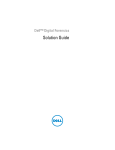
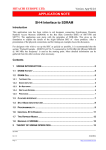
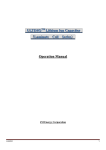
1
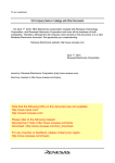
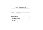
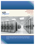
To our customers, Old Company Name in Catalogs and Other Documents On April 1st, 2010, NEC Electronics Corporation merged with Renesas Technology Corporation, and Renesas Electronics Corporation took over all the business of both companies. Therefore, although the old company name remains in this document, it is a valid Renesas Electronics document. We appreciate your understanding. Renesas Electronics website: http://www.renesas.com April 1st, 2010 Renesas Electronics Corporation Issued by: Renesas Electronics Corporation (http://www.renesas.com) Send any inquiries to http://www.renesas.com/inquiry. Notice 1. 2. 3. 4. 5. 6. 7. All information included in this document is current as of the date this document is issued. Such information, however, is subject to change without any prior notice. Before purchasing or using any Renesas Electronics products listed herein, please confirm the latest product information with a Renesas Electronics sales office. Also, please pay regular and careful attention to additional and different information to be disclosed by Renesas Electronics such as that disclosed through our website. Renesas Electronics does not assume any liability for infringement of patents, copyrights, or other intellectual property rights of third parties by or arising from the use of Renesas Electronics products or technical information described in this document. No license, express, implied or otherwise, is granted hereby under any patents, copyrights or other intellectual property rights of Renesas Electronics or others. You should not alter, modify, copy, or otherwise misappropriate any Renesas Electronics product, whether in whole or in part. Descriptions of circuits, software and other related information in this document are provided only to illustrate the operation of semiconductor products and application examples. You are fully responsible for the incorporation of these circuits, software, and information in the design of your equipment. Renesas Electronics assumes no responsibility for any losses incurred by you or third parties arising from the use of these circuits, software, or information. When exporting the products or technology described in this document, you should comply with the applicable export control laws and regulations and follow the procedures required by such laws and regulations. You should not use Renesas Electronics products or the technology described in this document for any purpose relating to military applications or use by the military, including but not limited to the development of weapons of mass destruction. Renesas Electronics products and technology may not be used for or incorporated into any products or systems whose manufacture, use, or sale is prohibited under any applicable domestic or foreign laws or regulations. Renesas Electronics has used reasonable care in preparing the information included in this document, but Renesas Electronics does not warrant that such information is error free. Renesas Electronics assumes no liability whatsoever for any damages incurred by you resulting from errors in or omissions from the information included herein. Renesas Electronics products are classified according to the following three quality grades: “Standard”, “High Quality”, and “Specific”. The recommended applications for each Renesas Electronics product depends on the product’s quality grade, as indicated below. You must check the quality grade of each Renesas Electronics product before using it in a particular application. You may not use any Renesas Electronics product for any application categorized as “Specific” without the prior written consent of Renesas Electronics. Further, you may not use any Renesas Electronics product for any application for which it is not intended without the prior written consent of Renesas Electronics. Renesas Electronics shall not be in any way liable for any damages or losses incurred by you or third parties arising from the use of any Renesas Electronics product for an application categorized as “Specific” or for which the product is not intended where you have failed to obtain the prior written consent of Renesas Electronics. The quality grade of each Renesas Electronics product is “Standard” unless otherwise expressly specified in a Renesas Electronics data sheets or data books, etc. “Standard”: 8. 9. 10. 11. 12. Computers; office equipment; communications equipment; test and measurement equipment; audio and visual equipment; home electronic appliances; machine tools; personal electronic equipment; and industrial robots. “High Quality”: Transportation equipment (automobiles, trains, ships, etc.); traffic control systems; anti-disaster systems; anticrime systems; safety equipment; and medical equipment not specifically designed for life support. “Specific”: Aircraft; aerospace equipment; submersible repeaters; nuclear reactor control systems; medical equipment or systems for life support (e.g. artificial life support devices or systems), surgical implantations, or healthcare intervention (e.g. excision, etc.), and any other applications or purposes that pose a direct threat to human life. You should use the Renesas Electronics products described in this document within the range specified by Renesas Electronics, especially with respect to the maximum rating, operating supply voltage range, movement power voltage range, heat radiation characteristics, installation and other product characteristics. Renesas Electronics shall have no liability for malfunctions or damages arising out of the use of Renesas Electronics products beyond such specified ranges. Although Renesas Electronics endeavors to improve the quality and reliability of its products, semiconductor products have specific characteristics such as the occurrence of failure at a certain rate and malfunctions under certain use conditions. Further, Renesas Electronics products are not subject to radiation resistance design. Please be sure to implement safety measures to guard them against the possibility of physical injury, and injury or damage caused by fire in the event of the failure of a Renesas Electronics product, such as safety design for hardware and software including but not limited to redundancy, fire control and malfunction prevention, appropriate treatment for aging degradation or any other appropriate measures. Because the evaluation of microcomputer software alone is very difficult, please evaluate the safety of the final products or system manufactured by you. Please contact a Renesas Electronics sales office for details as to environmental matters such as the environmental compatibility of each Renesas Electronics product. Please use Renesas Electronics products in compliance with all applicable laws and regulations that regulate the inclusion or use of controlled substances, including without limitation, the EU RoHS Directive. Renesas Electronics assumes no liability for damages or losses occurring as a result of your noncompliance with applicable laws and regulations. This document may not be reproduced or duplicated, in any form, in whole or in part, without prior written consent of Renesas Electronics. Please contact a Renesas Electronics sales office if you have any questions regarding the information contained in this document or Renesas Electronics products, or if you have any other inquiries. (Note 1) “Renesas Electronics” as used in this document means Renesas Electronics Corporation and also includes its majorityowned subsidiaries. (Note 2) “Renesas Electronics product(s)” means any product developed or manufactured by or for Renesas Electronics. APPLICATION NOTE H8S Family DRAM Control Introduction This sample task connects the DRAM to the H8S microcomputer by using the DRAM control function of the bus controller. Target Device H8S/2377R Contents 1. Specifications .................................................................................................................................... 2 2. Configuration..................................................................................................................................... 2 3. Description of Functions ................................................................................................................... 3 4. Description of Operation ................................................................................................................... 4 5. Description of Sample Program ........................................................................................................ 8 6. Flowchart........................................................................................................................................... 9 REJ06B0489-0200/Rev.2.00 June 2007 Page 1 of 12 H8S Family DRAM Control 1. Specifications This sample task connects the DRAM to the H8S microcomputer by using the DRAM control function of the bus controller. 2. Configuration Table 1 shows the configuration of this sample task. Table 1 Configuration of This Sample Task Component H8S/2377 CPU board Part no.: HSB8S2377F (Manufactured by Hokuto Denshi Co., Ltd.) EDO DRAM Part no.: MT4LC1M16E5TG6 (manufactured by Micron Technology, Inc.) Debugger High-performance Embedded Workshop Compiler H8S, H8/300, C/C++ compiler On-chip debugging emulator E10A-USB Part no.: HS0005KCU02H Specification Board power supply input: 3.3 V DC Operating frequency: 19.6608 MHz MCU operating mode: 4 Power supply for operation: 3.3 V DC Capacity: 1 Mwords × 16 bits Refresh cycle: 16 ms/1024 cycles Version 4.02.00.022 Version 6.01.02 1 Mword × 16 bits Note: * Connections of address pins DRAM MT4LC1M16E5TG6 H8S/2377R H8S/2377R DRAM A10 A9 A9 A8 WE A8 A7 OE A7 A6 A6 A5 A5 A4 A4 A3 A3 A2 A2 A1 A1 A0 LCAS CASL UCAS CASH RAS2 RAS HWR OE A[10:01] VCC VSS A[9:0]* I/O[15:00] VCC I/O[15:00] Address space: Area 2 0x400000 to 0x5FFFFF Figure 1 Connections between H8S/2377R and DRAM REJ06B0489-0200/Rev.2.00 June 2007 Page 2 of 12 H8S Family DRAM Control 3. Description of Functions By using the DRAM control function of the bus controller, this sample task directly links the DRAM to the H8S microcomputer, writes the fixed value 0x12345678 to address 0x400000, reads the address, and store it in the on-chip RAM area read_data. On-Chip RAM Area Name read_data REJ06B0489-0200/Rev.2.00 Data Size unsigned long Function Area to store data read from the DRAM June 2007 Page 3 of 12 H8S Family DRAM Control 4. Description of Operation 4.1 Initialization Processing Before the DRAM can be accessed, appropriate settings must be performed in order to connect the DRAM. (1) Initial Values Register Name DRAMCR Bit Name 10 to 8 RMTS2 to RMTS0 Value 001 DRAMCR 2 to 0 MXC2 to MXC0 010 PBDDR PCDDR ABWCR 7 to 0 7 to 0 2 ABW2 0x07 0xFF 0 PFCR0 2 CS2E 1 PFCR2 DRAMCR DRAMCR 1 15 12 OES OEE CAST 1 1 0 DRAMCR 14 RAST 0 DRACCR 9, 8 RCD1, RCD0 00 DRACCR 13, 12 TPC1, TPC0 00 ASTCR 2 AST2 0 DRAMCR DRAMCR 7 6 BE RCDM 1 0 RTCNT RTCOR 7 to 0 7 to 0 REFCR REFCR 7 RFSHE 10 to 8 RTCK2 to RTCK0 REJ06B0489-0200/Rev.2.00 0x00 152 1 1 Description DRAM Space Setting Areas 3 to 5: Regular space Area 2: DRAM space Address Multiplexing Setting (Sets the amount of row-address shift.) Sets to 10 bits. Address Bus Setting Sets address output for A10 to A0 Data Bus Width Setting Sets to 16 bits. RAS2 Pin Setting Sets the PG2 pin as the RAS2 pin. OE Pin Setting Sets the PH3 pin as the OE pin. Column Address Output Setting Sets to 2 states Row Address Output State Setting (Sets the RAS assertion timing) Asserts the signal at the falling edge of φ in a Tr cycle. Row Address Output State Setting (Controls wait between RAS and CAS) Sets to no wait. Precharge State Count Setting Sets to 1 state Wait Control Setting Sets area 2 to 2-state access space with no wait. Burst Access Mode Setting Enables burst mode. Sets to RAS-up mode Refresh Control Setting Resets the counter. Sets the refresh interval to within 16 ms/1024 cycles. Enables refresh. Counts on φ/2 June 2007 Reference Section 4.1 (2) 4.1 (3) 4.1 (4) 4.1 (5) 4.1 (6) 4.1 (7) 4.1 (8) Page 4 of 12 H8S Family DRAM Control (2) DRAM Space Setting The address space for the H8S microcomputer is divided into eight areas in units of 2 Mbytes. A bus can be set for each area. The DRAM can be connected to Areas 2 to 5. The following areas can be assigned to the DRAM space: Area 2 if the space is 2 Mbytes or less; Areas 2 to 3 if the space if 4 Mbytes or less; or Areas 2 to 5 if the space is more than 4 Mbytes and up to 8 Mbytes. The sample task in this application note uses 2-Mbyte DRAM and assigns Area 2 to the DRAM space with an available address range of 0x400000 to 0x5FFFFF. (3) Address Multiplexing Setting The DRAM space is multiplexed in terms of row and column addresses. Therefore, the amount of a row-address shift needs to be set according to the address width (memory capacity) of the DRAM to be used. Because the DRAM used in this application note has an address width of 10 bits, the row-address shift amount is also set to 10 bits. (4) Address Bus Setting To use as an address bus, the output mode must be set using the DDR register of the I/O port. (5) Data Bus Setting The data width (16 bits) for the DRAM used in the application note must be set. Note that because access is made in units of 16 bits, the least significant bit of an address is not connected, and that connections are shifted by 1 bit. (See the connection diagram in section 2, Configuration.) (6) Signal Timing Adjustment Appropriate settings must be provided according to the AC characteristic of the DRAM to be connected and the operating frequency of the microcomputer. The figure below shows fundamental access timing. REJ06B0489-0200/Rev.2.00 June 2007 Page 5 of 12 H8S Family DRAM Control Tp Tr Tc1 Tc2 φ Address bus Row address Column address tRAH RASn (CSn) tRCD tCAS UCAS, LCAS WE (HWR) For reading High level OE (RD) Data bus WE (HWR) For writing OE (RD) High level tDS Data bus Note: n = 2 to 5 Figure 2 Fundamental Access Timing of DRAM Register to Adjust Timing Min. 10 ns Min. 14 ns Microcomputer Access Timing 19.6608 MHz, 50.86 ns φ/2 = 25.43 ns 1.5φ = 76.29 ns Min. 10 ns φ = 50.86 ns Min. 0 ns Min. 40 ns φ = 50.86 ns φ = 50.86 ns DRAMCR (CAST), AST (AST2) AST (AST2) DRACCR (TPC) Symbol φ Description Access cycle DRAM Specification tRAH tRCD tCAS Row address hold time Delay time between RAS and CAS CAS pulse width tDS Tp Data-in setup time Precharge time DRAMCR (RAST) DRACCR (RCD) As indicated in the above table, the DRAM used in the application note can be accessed at fundamental access timing. If a given access timing cannot meet the DRAM specifications, it can be modified using the timing adjustment register. For details, refer to the hardware manual. REJ06B0489-0200/Rev.2.00 June 2007 Page 6 of 12 H8S Family DRAM Control (7) Burst Access Mode Setting A burst access mode can be set when connecting DRAM that supports the burst mode. The burst mode refers to a mode that permits high-speed access when identical row addresses are encountered in succession, by simply changing column addresses after the row address is output. In the RAS-up mode, bust operations are performed only when the DRAM space is contiguous, such that if access to another external space occurs in the midst of access to the DRAM space, the burst operations cease. In the RAS-down mode, burst operations continue even if access to another external space occurs in the midst of access to the DRAM space. The figure below illustrates examples of burst mode operation timing. Because DRAM with a fast page mode feature is used in this application note, a RAS-up mode with a burst mode will be set. Tp Tr Tc1 Tc2 Tc1 Tc2 φ Address bus Row address Column address 1 Column address 2 RASn (CSn) UCAS, LCAS WE (HWR) For reading High level OE (RD) Data bus WE (HWR) For writing OE (RD) High level Data bus Figure 3 Burst Mode Operation Timing (8) Refresh Control Setting In accordance with DRAM specifications, a CBR refresh can be issued at fixed intervals. The refresh interval is set to 15.563 µs in this application note. Refreshing of DRAM: 16 ms/1024 cycles = 15.625 µs Refresh timing in this application note: Operating frequency 19.6608 MHz = 50.86 ns Counting at φ/2, 15.625 µs/(50.86 ns × 2) ≅ 153 cycles 50.86 ns × 2 × 153 ≅ 15.563 µs Since 15.563 µs < 15.625 µs, set the RTCOR register to 152 (153-1). 4.2 DRAM Access The above settings enable access to the DRAM. For this application, the DRAM space is 0x400000 to 0x5FFFFF, with an access unit of 4 bytes. REJ06B0489-0200/Rev.2.00 June 2007 Page 7 of 12 H8S Family DRAM Control 5. Description of Sample Program 5.1 File Configuration Table 2 shows file configuration of this sample task. Table 2 Description of Functions File Name resetprg.c intprg.c dbsct.c H8S_2377_1.c Iodefine.h stacksct.h 5.2 Specification Executed from reset vector address 0 if the MCU is reset. Executed if an interrupt other than a reset occurs. Sets start and end addresses of the section used by _INITSCT function in resetprg.c to section initialization table. For details, refer to sections 9 and 10 in the H8S, H8/300H Series C/C++ Compiler, Assembler, and Optimization Linkage Editor User’s Manual. Main routine of this sample task. Configuration definition file of internal registers. Defines stack size. Linkage The linkage addresses of each section are as follows. In the HEW project files, the linkage addresses can be referenced and set by Category: section of Link/librarq tab in option – Standard Toolchain. Section PResetPRG PIntPRG P C$DSEC C$BSEC D B R S Start Address 0x000400 0x000800 0xFF6000 0xFFBDF0 REJ06B0489-0200/Rev.2.00 June 2007 Page 8 of 12 H8S Family DRAM Control 6. Flowchart Reset Start Set interrupt mask. set_imask_ccr (1) Initialize sections. - Initialize the uninitialized data area (area B). - Copy initialization data area (area D) from the ROM to RAM (area R). INITSCT () Provide initial settings to internal registers for SDRAM. For the setting values, refer to section 4.1, Initialization Processing. Clear interrupt mask. set_imask_ccr (0) DRAM 0x400000 ← 0x12345678 DRAM write read_data = Contents of 0x400000 in the DRAM DRAM read loop REJ06B0489-0200/Rev.2.00 June 2007 Page 9 of 12 H8S Family DRAM Control References Document Name H8S/2378, H8S/2378R Group Hardware Manual REJ06B0489-0200/Rev.2.00 How to Get the Document Download from the website of Renesas Technology Corp. June 2007 Page 10 of 12 H8S Family DRAM Control Website and Support Renesas Technology Website http://www.renesas.com/ Inquiries http://www.renesas.com/inquiry [email protected] Revision Record Rev. 1.00 2.00 Date Mar.09.05 Jun.15.07 Description Page — Page 2 Page 2 Page 2 Page 2 Page 3 Pages 3, 7, 9 Page 4 Page 7 Page 8 Page 8 Page 9 REJ06B0489-0200/Rev.2.00 Summary First edition issued Correction to the DRAM refresh cycle in table 1 Addition of three components to table 1 Correction to the vocabulary used as “product code” to “Part no.”, in table 1. Correction to the pin name in figure 1 from “CS2” to “RAS2” Correction on the data size “unsigned int” to “unsigned long”, in the table Correction on the fixed value of address “0x400000” to “0x12345678 and an access unit to “4 bytes” Correction on the content in “(1) Initial Values” Correction on the content in “(8) Refresh Control Setting” Deletion of URL under table 2 Correction on the text of “5.1 File Configuration” Correction on the content in “6 Flowchart” June 2007 Page 11 of 12 H8S Family DRAM Control Notes regarding these materials 1. 2. 3. 4. 5. 6. 7. 8. 9. 10. 11. 12. 13. This document is provided for reference purposes only so that Renesas customers may select the appropriate Renesas products for their use. Renesas neither makes warranties or representations with respect to the accuracy or completeness of the information contained in this document nor grants any license to any intellectual property rights or any other rights of Renesas or any third party with respect to the information in this document. Renesas shall have no liability for damages or infringement of any intellectual property or other rights arising out of the use of any information in this document, including, but not limited to, product data, diagrams, charts, programs, algorithms, and application circuit examples. You should not use the products or the technology described in this document for the purpose of military applications such as the development of weapons of mass destruction or for the purpose of any other military use. When exporting the products or technology described herein, you should follow the applicable export control laws and regulations, and procedures required by such laws and regulations. All information included in this document such as product data, diagrams, charts, programs, algorithms, and application circuit examples, is current as of the date this document is issued. Such information, however, is subject to change without any prior notice. Before purchasing or using any Renesas products listed in this document, please confirm the latest product information with a Renesas sales office. Also, please pay regular and careful attention to additional and different information to be disclosed by Renesas such as that disclosed through our website. (http://www.renesas.com) Renesas has used reasonable care in compiling the information included in this document, but Renesas assumes no liability whatsoever for any damages incurred as a result of errors or omissions in the information included in this document. When using or otherwise relying on the information in this document, you should evaluate the information in light of the total system before deciding about the applicability of such information to the intended application. Renesas makes no representations, warranties or guaranties regarding the suitability of its products for any particular application and specifically disclaims any liability arising out of the application and use of the information in this document or Renesas products. With the exception of products specified by Renesas as suitable for automobile applications, Renesas products are not designed, manufactured or tested for applications or otherwise in systems the failure or malfunction of which may cause a direct threat to human life or create a risk of human injury or which require especially high quality and reliability such as safety systems, or equipment or systems for transportation and traffic, healthcare, combustion control, aerospace and aeronautics, nuclear power, or undersea communication transmission. If you are considering the use of our products for such purposes, please contact a Renesas sales office beforehand. Renesas shall have no liability for damages arising out of the uses set forth above. Notwithstanding the preceding paragraph, you should not use Renesas products for the purposes listed below: (1) artificial life support devices or systems (2) surgical implantations (3) healthcare intervention (e.g., excision, administration of medication, etc.) (4) any other purposes that pose a direct threat to human life Renesas shall have no liability for damages arising out of the uses set forth in the above and purchasers who elect to use Renesas products in any of the foregoing applications shall indemnify and hold harmless Renesas Technology Corp., its affiliated companies and their officers, directors, and employees against any and all damages arising out of such applications. You should use the products described herein within the range specified by Renesas, especially with respect to the maximum rating, operating supply voltage range, movement power voltage range, heat radiation characteristics, installation and other product characteristics. Renesas shall have no liability for malfunctions or damages arising out of the use of Renesas products beyond such specified ranges. Although Renesas endeavors to improve the quality and reliability of its products, IC products have specific characteristics such as the occurrence of failure at a certain rate and malfunctions under certain use conditions. Please be sure to implement safety measures to guard against the possibility of physical injury, and injury or damage caused by fire in the event of the failure of a Renesas product, such as safety design for hardware and software including but not limited to redundancy, fire control and malfunction prevention, appropriate treatment for aging degradation or any other applicable measures. Among others, since the evaluation of microcomputer software alone is very difficult, please evaluate the safety of the final products or system manufactured by you. In case Renesas products listed in this document are detached from the products to which the Renesas products are attached or affixed, the risk of accident such as swallowing by infants and small children is very high. You should implement safety measures so that Renesas products may not be easily detached from your products. Renesas shall have no liability for damages arising out of such detachment. This document may not be reproduced or duplicated, in any form, in whole or in part, without prior written approval from Renesas. Please contact a Renesas sales office if you have any questions regarding the information contained in this document, Renesas semiconductor products, or if you have any other inquiries. 2007. Renesas Technology Corp., All rights reserved. REJ06B0489-0200/Rev.2.00 June 2007 Page 12 of 12