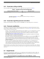
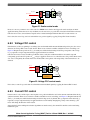
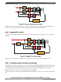
1
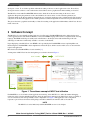
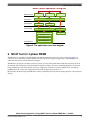
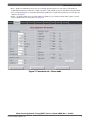
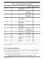
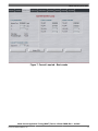
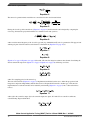
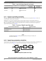
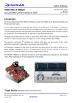
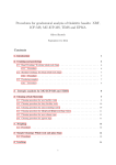
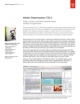
Freescale Semiconductor
Application Note
Document Number:AN4642
Rev. 1, 01/2013
Motor Control Application Tuning
(MCAT) Tool for 3-Phase PMSM
by:
Marek Stulrajter, Pavel Sustek
Contents
1 Introduction
1
Introduction................................................................1
This application note describes a Freescale motor control
tuning solution known as Motor Control Application Tuning
(MCAT) tool. MCAT is a graphical tool dedicated to motor
control developers and the operators of modern electrical
drives. The main feature of proposed approach is automatic
calculation and real-time tuning of selected control structure
parameters. Connecting and tuning new electric drive setup
becomes easier because the MCAT tool offers a possibility to
split the control structure and consequently to control the
motor at various levels of cascade control structure.
2
Motivation..................................................................1
3
Software Concept......................................................2
4
Key Features..............................................................3
5
Target Applications...................................................3
6
MCAT tool for 3-phase PMSM................................5
7
References...............................................................35
2 Motivation
An electric drive is known as a set of several subsystems such
as electric motor with load, controlled supply source, control
unit and wide range of sensors, which provide a conversion of
electric energy to a specific mechanical movement.
Performing the mechanical movement according to certain
specifications requires a suitable control strategy of the
electric motor. Based on the motor type and the application
requirements there are several dedicated control methods. In
general, the control techniques are very complex and require
knowing of controlled system parameters and control structure
parameters. This is a matter of experience in the motor control
theory which can cause difficulties to motor control
© 2013 Freescale Semiconductor, Inc.
Software Concept
developers or users. To avoid these problems and make the tuning of the motor control applications easier, Freescale has
developed software solution to control and tune the electrical drives from a graphical environment running on a host PC.
The MCAT tool runs under FreeMASTER online monitor, which allows the real-time tuning of the motor control
application. Respecting the parameters of the controlled drive, the correct values of control structure parameters are
calculated, which can be directly updated to the application or stored in an application static configuration file. The electrical
subsystems are modeled using physical laws and the parameters estimation algorithms are based on Pole-placement method.
The given solution is a graphical user-friendly tool that allows tuning of the application within minutes and will save the user
much of the work.
3 Software Concept
The MCAT tool is a user-friendly graphical plug-in tool for Freescale’s FreeMASTER dedicated to debugging the motor
control application. The environment of MCAT tool is based on HTML language whereas the tool engine is based on Jscript
language. The HTML and Jscript are widely used on the Internet so the design can be made with the help of the webauthoring tools which are commercially available or even free on the Internet.
Proper displaying of the MCAT tool as an HTML code is provided by the FreeMASTER software exploiting Microsoft
Internet Explorer. FreeMASTER software implements an ActiveX object, which is used to enable access to and control the
target board application.
More details about FreeMASTER tool can be found in [1 ].
An integration of MCAT tool into the development process chain is shown in Figure 1.
Figure 1. The software concept of MCAT tool utilization
FreeMASTER, as a tool for hard-real time applications monitoring, allows MCAT tool to utilize the runtime debugging
features in order to tune the embedded application. Once the application is tuned properly, MCAT tool offers a possibility to
store all constants in a file and export them as static configuration, see Figure 1. The application static configuration
represents a part of Freescale reference S/W package and will be added into the reference S/W as a header file.
NOTE
The MCAT tool can be linked only with FreeMASTER version 1.3.16 or higher.
Motor Control Application Tuning (MCAT) Tool for 3-Phase PMSM, Rev. 1, 01/2013
2
Freescale Semiconductor, Inc.
Key Features
4 Key Features
The given approach is designed to tune the motor control applications, in other words it provides the support for embedded
applications. The application meets the following performance specifications:
•
•
•
•
•
•
•
•
•
•
•
Supports up to three motor applications. Keeping an independent access to each motor.
Supports embedded applications that are compliant with MCAT tool standards
Utilizes a Pole Placement method for control parameters estimation
Real-time tuning and updating of control parameters
Offers a preview of the static configuration of tuned parameters
Generates an output file with static configuration of tuned parameters
MCU independent. It supports platforms such as Kinetis, MPC and DSC.
Applicable for Freescale microcontrollers only
Plug-in tool for FreeMASTER, not available as a stand-alone tool
Offers basic and expert tuning mode
Modular S/W concept, easily configurable
5 Target Applications
In recent times, there are plenty of servo-drive applications employing various types of electric motors. Freescale, based on
its experiences, mainly focuses on permanent magnet types of electric drives such as Permanent Magnet Synchronous Motor
(PMSM) and Brushless Direct Current (BLDC) motor. Both of them are very popular in wide variety of the motor control
applications due to their performance, efficiency, reliability, easy controlling and so on. Another type of motors Asynchronous Induction Motor (ACIM) or Switched Reluctance Motor (SRM) are not widely used as servo-drives, however
they are still popular due to their absence of expensive permanent magnets.
The application note describes the PMSM application tuning variant as a first motor module of MCAT tool.
From a wide spectrum of PMSM control techniques the most common one has been chosen for the purpose of electric drives
tuning by using MCAT tool. The most popular and widely used control strategy for PMSM motors is Field Oriented Control
(FOC) which is characterized by smooth rotation over the entire speed range of the motor, full torque control at zero speed,
and fast acceleration/deceleration.
5.1 PMSM Field Oriented Control
Field Oriented Control [2 ] also called vector control, is based on the cascade structure with inner current loop and outer
speed loop, Figure 2. The control loops arranged in series represents hierarchical structure which is characteristic by a
feedback, hence the name closed loop system. Proportional-integral (PI) controllers are the most commonly used as feedback
controllers, that provide an “error” calculation as the difference between a measured process variable and desired “reference”
variable. The PI controller attempts to minimize the control loop error by adjusting the actuating signal in other words the
controller output signal.
Motor Control Application Tuning (MCAT) Tool for 3-Phase PMSM, Rev. 1, 01/2013
Freescale Semiconductor, Inc.
3
Target Applications
Figure 2. Cascade structure, speed FOC of PMSM
There are two types of PI controllers mostly used in the control algorithms. We distinguish between parallel and recurrent
form of the PI controller. Based on the form, the PI controller algorithm involves two separate constant parameters: the
proportional component KP and integral component KI for parallel form or their equivalents CC1 and CC2 for recurrent form.
Setting of these constants depends on the required control loop behavior such as the loop bandwidth or attenuation.
As seen in Figure 2, the control structure can be extended by additional optional blocks placed in the feed-forward path of the
control loop. They are called Zero Cancellation blocks and play an important role in term of compensation of a closed loop
“zero” introduced by a PI controller. Ramp block modifies the edges of speed step change command and introduces a slope
behavior to the reference speed request.
Proposed MCAT tool helps the user to properly calculate the constants of the control structure with respecting the overall
system parameters as well as the parameters of the control.
5.2 Application cases tree
The MCAT tool was designed to tune and control the applications employing up to three motors. Such a strategy covers wide
range of the multiple motor applications with different conditions. Cascade control approach allows the PMSM motor to be
controlled by following the FOC principles. Additional feature of the MCAT tool is an open loop scalar control of PMSM
motor. The last but definitely not least feature of the MCAT tool is position/speed feedback option. In recent times, there are
plenty of various sensors such as resolver or encoder demanded. Very popular and often required is also sensorless design of
a PMSM control. All main MCAT tool features reflecting the possible application cases are summarized in Figure 3.
Motor Control Application Tuning (MCAT) Tool for 3-Phase PMSM, Rev. 1, 01/2013
4
Freescale Semiconductor, Inc.
MCAT tool for 3-phase PMSM
Motor Control Application Tuning tool
Number of motors
Control strategy
Three motors
PMSM motor
Type of motor
Speed feedback
Two motors
One motor
Sensor based
Sensorless
Field Oriented Control
Scalar Control
Cascade structure
Open Loop
Voltage FOC Control
Current FOC Control
Control Structure
Speed FOC Control
Figure 3. The application cases tree diagram
6 MCAT tool for 3-phase PMSM
The MCAT tool is a graphical tool with friendly environment and intuitive control. As can be seen in Figure 4, the tool
consists of motor selector bar, tab menu and the workspace. The proposed approach supports up to three PMSM motors,
while each motor has its own tab menu and workspace.
The MCAT tool represents a modular concept that consists of several sub-modules. Each sub-module represents one tab in
the tab menu. The arrangement of the sub-modules is flexible according to the needs of embedded application. Several tab
menu combinations can be created based on the type of application, for instance sensorless applications do not need any
POSPE Sensors tab, torque control applications do not need any Speed Loop tab and so on.
Based on this, the initial setting of the MCAT tool will be provided by Freescale team developing the motor control reference
designs.
Motor Control Application Tuning (MCAT) Tool for 3-Phase PMSM, Rev. 1, 01/2013
Freescale Semiconductor, Inc.
5
MCAT tool for 3-phase PMSM
Figure 4. MCAT tool environment
Predefined MCAT tool will be a part of reference software for dedicated MCU. Since the tuning tool cannot be used as a
standalone, it will be included in the FreeMASTER project by default.
The MCAT tool workspace is unique for each tab and detailed overview of each available tab is provided in the following
chapters.
6.1 Introduction tab
An Introduction tab can be considered as a voluntary tab. It provides a room for describing or introducing the targeted MC
application, Figure 4.
6.2 Parameters tab
A Parameters tab is dedicated for entering the input application parameters. It is a mandatory tab due to its high level of
dependency with other tabs. To ensure proper MCAT tool functionality and control parameter calculation accuracy an
attention must be paid when entering the input application parameters into required cells. An impact of each required input is
shown in Table 1. Number of input parameters that need to be filled depends on the selected application tuning mode. The
application tuning mode can be changed on the right side of motor selector bar and offers two options: basic and expert
mode.
Application tuning modes available in Parameters tab are as follows:
Motor Control Application Tuning (MCAT) Tool for 3-Phase PMSM, Rev. 1, 01/2013
6
Freescale Semiconductor, Inc.
MCAT tool for 3-phase PMSM
• Basic – highly recommended for users who are not enough experienced in motor control theory. The number of
required input parameters is reduced according to the Table 1. The mandatory cells are with white background while
the rest of input parameters are calculated automatically by MCAT tool engine. These parameters are read-only and
shadowed, see Figure 5 .
• Expert – all inputs parameters are accessible and freely editable by a user. However, their setting requires a certain
level of expertise in motor control theory, see Figure 6.
Figure 5. Parameters tab – Basic mode
Motor Control Application Tuning (MCAT) Tool for 3-Phase PMSM, Rev. 1, 01/2013
Freescale Semiconductor, Inc.
7
MCAT tool for 3-phase PMSM
Figure 6. Parameters tab – Expert mode
The Table 1 shows the list of the MCAT tool input parameters with their physical units, brief description, the impacted
algorithms and accessibility status in basic mode.
Table 1. Inputs of the Parameter tab
Parameter Name
Units
Description
Use in constant
calculation
Basic mode
accessibility
pp
[-]
Motor pole pairs
Speed and Position
module
Yes
Rs
[Ω]
Resistance of one
motor phase
Current PI controller
Yes
Ld
[H]
Direct Inductance of
one motor phase
Current PI controller
Lq
[H]
BEMF Observer
Yes
BEMF Observer
Quadrature Inductance Current PI controller
of one motor phase
Yes
BEMF Observer
ke
[V.sec/rad]
Back-EMF constant
BEMF Observers
Yes
J
[Kg.m2]
Drive Inertia
Speed PI controller
Yes
Iph nom
[A]
Nominal phase current
Current scale
calculation
Yes
Uph nom
[V]
Nominal phase voltage
Voltage scale
calculation
Yes
Table continues on the next page...
Motor Control Application Tuning (MCAT) Tool for 3-Phase PMSM, Rev. 1, 01/2013
8
Freescale Semiconductor, Inc.
MCAT tool for 3-phase PMSM
Table 1. Inputs of the Parameter tab (continued)
Parameter Name
Units
Description
Use in constant
calculation
Basic mode
accessibility
N required max
[rpm]
Maximal required speed Speed scale calculation Yes
in the application. It is
not a speed scale!
Imax
[A]
HW current sensing
scale
Current PI controller
HW DC-Bus voltage
scale
Current PI controller
U DCB max
[V]
No
BEMF Observer
Speed Controller
No
BEMF Observer
Speed Controller
U DCB trip
[V]
Trigger value that
Fault protection
switches an external
DC-Bus braking resistor
on
No
U DCB under
[V]
Voltage value that
generates DC-Bus
UNDER VOLTAGE
fault
Fault protection
No
U DCB over
[V]
Voltage value that
generates DC-Bus
OVER VOLTAGE fault
Fault protection
No
N max
[rpm]
Speed scale – maximal Speed and position
value of electrical
BEMF Observer
angular velocity
No
U max
[V]
Voltage scale –
maximal value of FOC
Current PI Controller
No
Tracking Observer
BEMF Observer
E max
[V]
Back-EMF voltage
scale
BEMF Observer
No
kt
[Nm/A]
Torque constant
Speed PI controller
No
Align current / voltage
[A] / [V]
DC value of current or
voltage for rotor
alignment
Rotor alignment
No
Align duration
[sec]
Duration of rotor
alignment
Rotor alignment
No
The parameters of the controlled motor can be acquired from a motor datasheet provided by motor manufacturer or from
laboratory measurement.
6.2.1 Parameter modification
All parameter cells are filled automatically with predefined data downloaded from an external file. The input parameter cells
are freely accessible for editing in accordance to the selected tuning mode, as it is shown in Table 1. There are four user
buttons on the page with the following functionality:
• Update FRM – the DC voltage or current and the duration of applied alignment state can be updated by using this
button. The button is disabled in basic tuning mode.
Motor Control Application Tuning (MCAT) Tool for 3-Phase PMSM, Rev. 1, 01/2013
Freescale Semiconductor, Inc.
9
MCAT tool for 3-phase PMSM
• Calculate – the button is disabled by default. In case that the tuning mode has changed from an expert to a basic mode
and at least one of the input application parameters has changed as well, a new set of application scales have to be
recalculated. The Calculate button provides calculation and update of application scales values.
• Reload Data – the button is disabled by default. If the value in a particular field has changed, the background of the cell
is changed from white to pink color for the purpose of signalization the changes and the button becomes enabled. By
pressing the Reload Data button all modified cells will be filled with original values taken from the file. After
successful data reload, the background of the cells becomes white and the button gets disabled
• Store Data – the button is disabled by default. If the value in a particular field has changed, the background of the cell
is changed from white to pink color for the purpose of signalization the changes and the button becomes enabled. By
pressing the Store Data button all new values from modified cells will be saved into the file. After successful data
saving, the background of the cells becomes white and the button gets disabled.
The editing fields accept only numeric characters. The parameter values are fully under a user responsibility and no
additional checking is applied to those items. The typical range of the parameter value appears when the mouse pointer is in a
parameter name focus.
6.3 Current Loop tab
The Current Loop (CL) is a tab designed for tuning of the current control loop. The current control loop is the most inner
loop in the cascade control structure of vector controlled PMSM. One of the FOC features is separate controlling of the flux
(d axis) and torque (q axis) components of the current, Figure 2. Due to this, PMSM control structure has two current loops
and each of them consists of a PI controller and an optional zero-cancellation block.
The CL tab is logically divided into two parts. The first part represents an input data field with required control loop
parameters needed for PI controller parameter calculation. The second one is an output data field which displays the
calculated parameters of PI controllers in both d and q axis. All PI controller constants are calculated from the motor
parameters, application scales and current loop parameters.
Application tuning modes available in Current Loop tab:
• Basic – highly recommended for users who are not experienced enough in motor control theory. There are no input
parameters required in this mode. All input parameters of the CL are estimated from the motor and application
parameters automatically by MCAT tool engine. The cells requiring these parameters are shadowed with the status
read-only, Figure 7.
• Expert – all input parameters cells of the CL are accessible and freely editable by the user, as given in Figure 8.
However, their setting requires a certain level of expertise in motor control theory.
Motor Control Application Tuning (MCAT) Tool for 3-Phase PMSM, Rev. 1, 01/2013
10
Freescale Semiconductor, Inc.
MCAT tool for 3-phase PMSM
Figure 7. Current Loop tab – Basic mode
Motor Control Application Tuning (MCAT) Tool for 3-Phase PMSM, Rev. 1, 01/2013
Freescale Semiconductor, Inc.
11
MCAT tool for 3-phase PMSM
Figure 8. Current Loop tab – Expert mode
The Table 2 shows the list of the current loop input parameters with their physical units, brief description, the impacted
algorithms and accessibility status in basic mode.
Table 2. Inputs of the Current Loop tab
Parameter Name
Sample Time
Units
[sec]
Description
CL sampling time
Use in Constant
Calculation
Current PI controller
Basic Mode
Accessibility
NO
Zero-compensator
F0
[Hz]
Current loop bandwidth Current PI controller
NO
Zero-compensator
ξ
Output limit
[-]
[%]
Current loop
attenuation
Limit of the current PI
controllers
Current PI controller
NO
Zero-compensator
NO
6.3.1 Current Loop Setting Variability
Two types of PI controllers and optional zero-cancellation blocks (Figure 2 )lead to several variations of current control loop
structure.
Motor Control Application Tuning (MCAT) Tool for 3-Phase PMSM, Rev. 1, 01/2013
12
Freescale Semiconductor, Inc.
MCAT tool for 3-phase PMSM
The MCAT tool covers both options, it means it supports both types of PI controllers and offers an opportunity to use the
optional zero-cancellation blocks. Moreover, including the variability of data type representation, there are several modes
available that are required to be supported by the current loop tab, see Table 3.
Table 3. Summary of Current Loop setting modes
The control loop available mode
Applicable changes
PI controllers
Parallel / Recurrent form
Zero-cancellation blocks
Allowed / Non allowed
Data type representation
FIX, FLOAT arithmetic
NOTE
All settings shown in Table 3 will be predefined by Freescale developer according to the
MC reference application.
6.3.2 Current loop parameters calculation
The parameters of the PI controllers in current loop are calculated by exploiting the pole placement (PP) method. Pole
placement method is an approach of the feedback control system theory to place the closed-loop poles of a plant in predetermined locations. The PP method applied to the closed-loop system leads to desired controlled system behavior.
A simplified closed current control loop shown in Figure 9, is used for deriving the PI controller parameters calculation
process.
Zero cancellation
ireq
PI controller
ireq_ZC
RL circuit
ureq
ireal
Tel
ireal
Figure 9. Simplified current control loop
Considering a general form of closed loop with RL model as a plant of first order and PI controller:
Equation 1.
Equation 2.
where L is the stator inductance and R is a stator resistance. The closed loop transfer function is derived in Laplace domain as
follows:
Equation 3.
The PI controller however, introduced a zero to the closed loop transfer function for command changes, located at -KI_I/KP_I.
This derivative characteristic of the loop increases the system overshoot, lowering the potential closed loop bandwidth. Due
to this, the zero of the PI controller must be compensated. This can be done by introducing a zero-cancellation block in the
feed-forward path, which has the following transfer function:
Motor Control Application Tuning (MCAT) Tool for 3-Phase PMSM, Rev. 1, 01/2013
Freescale Semiconductor, Inc.
13
MCAT tool for 3-phase PMSM
Equation 4.
The current loop transfer function with the zero-cancellation block in feed-forward is then:
Equation 5.
Having the closed loop with canceled zero (Equation 5 on page 14), the PI controller can be designed by comparing the
closed loop characteristic polynomial with that of a standard second order system as:
Equation 6.
where ω0 is the natural frequency of the closed loop system (loop bandwidth) and ξ is the loop attenuation. The proportional
and integral gains of the PI controller can be therefore calculated from (Equation 6 on page 14) as:
Equation 7.
Equation 8.
(Equation 7 on page 14, Equation 8 on page 14) describe a PI controller design in continuous time domain. Considering the
discrete domain the expressions (Equation 7 on page 14, Equation 8 on page 14) will change as follows:
Equation 9.
Equation 10.
where TS is sampling period of the current loop.
The form of PI controller (Equation 1 on page 13) implementation which allows the user to define the proportional and
integration components independently without interaction is called parallel PI controller. Another type of PI controller
implementation is recurrent form that can be reached by transforming (Equation 1 on page 13) into a discrete domain as
follows:
Equation 11.
where u(k) is the controller output, e(k) is the controller input error signal, CC1 and CC2 are controller coefficients
calculated using Trapezoidal method:
Equation 12.
Motor Control Application Tuning (MCAT) Tool for 3-Phase PMSM, Rev. 1, 01/2013
14
Freescale Semiconductor, Inc.
MCAT tool for 3-phase PMSM
Equation 13.
The zero cancellation transfer function (Equation 4 on page 14) can be also transformed into Z domain using Backward Euler
method. Then the discrete implementation is therefore given by:
Equation 14.
It is clear that (Equation 14 on page 15) is a simplified form of 1st order Butterworth LP filter in IIR implementation. So the
zero cancellation block physically behaves as a low pass filter, smoothing the input command. It therefore allows increasing
of the loop gain, achieving higher bandwidth.
In depends on the PI controller implementation, the controller constants (Equation 9 on page 14, Equation 10 on page 14) or
(Equation 12 on page 14, Equation 13 on page 15) are used in case of floating point data representation. The discrete
implementation of PI controllers in the fixed point arithmetic platform requires the scaling approach to keep all signals in the
range <-1, 1). Detailed description of proper PI controller’s parameters scaling is in [3 ] , [4 ].
6.3.3 Parameter modification
All parameter cells are filled automatically with predefined data downloaded from an external file. The parameter cells are
freely accessible for editing according to the selected tuning mode, as shown in Table 2. There are four user buttons on the
page with the following functionality:
• Calculate – the button is disabled by default. The button becomes enabled as soon as one of the input Loop Parameters
is changed. The background of the cell is changed from white to pink color for the purpose of change signalization. By
pressing the Calculate button all PI controller parameters are recalculated according to the Current loop parameters
calculation.
• Update FRM – the button is enabled by default. By pressing the button, the application PI controller parameters on the
embedded side are updated with the ones displayed in output field data.
• Reload Data – the button is disabled by default. The button becomes enabled as soon as one of the input Loop
Parameters is changed. The background of the cell is changed from white to pink color for the purpose of change
signalization. By pressing the Reload Data button all the modified cells will be rewritten with original values taken
from the file. After successful data reload, the background of the cells becomes again white and the button gets
disabled.
• Store Data – the button is disabled by default. The button becomes enabled as soon as one of the input Loop Parameters
is changed. The background of the cell is changed from white to pink color for the purpose of change signalization. By
pressing the Store Data button all new values from modified cells will be saved into the file. After successful data
saving, the background of the cells becomes white and the button gets disabled.
The editing fields accept only numeric characters. The parameter values are fully under user responsibility and no additional
checking is applied to those items. The typical range of the parameter value appears when the mouse pointer is in a parameter
name focus.
6.4 Speed Loop Tab
The Speed Loop (SL) is a tab designed for tuning the speed control loop. The speed control loop is an outer loop in the
cascade control structure of vector controlled PMSM. Speed loop consists of a PI controller and optional blocks like zerocancellation or ramp function.
Motor Control Application Tuning (MCAT) Tool for 3-Phase PMSM, Rev. 1, 01/2013
Freescale Semiconductor, Inc.
15
MCAT tool for 3-phase PMSM
The SL tab is logically divided into two parts. The first part represents input data fields with required control loop parameters
needed for PI controller parameter calculation. The second one is an output data field which displays the calculated
parameters of the speed controller. The PI controller constants are calculated from the motor parameters, application scales
and speed loop parameters.
Application tuning modes available in Speed Loop tab are as follows:
• Basic – highly recommended for users which are not enough experienced in motor control theory. There are no input
parameters required in this mode. All input parameters of the SL are estimated from the motor and application
parameters automatically by MCAT tool engine. The cells requiring these parameters are shadowed with the status
read-only, as in Figure 10.
• Expert – all input parameters cells of the SL are accessible and freely editable by an user, as in Figure 11. However,
their setting requires a certain level of expertise in motor control theory.
Figure 10. Speed Loop tab – Basic mode
Motor Control Application Tuning (MCAT) Tool for 3-Phase PMSM, Rev. 1, 01/2013
16
Freescale Semiconductor, Inc.
MCAT tool for 3-phase PMSM
Figure 11. Speed Loop tab – Expert mode
The Table 4 shows the list of the speed loop input parameters with their physical units, brief description, the impacted
algorithms and accessibility status in basic mode.
Table 4. Input of the Speed Loop tab
Parameter Name
Sample time
Units
[sec]
Description
CL sampling time
Use in constant
calculation
Current PI controller
Basic mode
accessibility
NO
Zero-compensator
F0
[Hz]
Current loop bandwidth Current PI controller
NO
Zero-compensator
ξ
[-]
Current loop
attenuation
Current PI controller
Inc Up
[rpm/sec]
Speed increasing with
the increment
Ramp function
NO
Inc Down
[rpm/sec]
Speed decreasing with
the increment
Ramp function
NO
Filter points
[points #]
Moving Average Filter
Samples
NO
Zero-compensator
NO
Table continues on the next page...
Motor Control Application Tuning (MCAT) Tool for 3-Phase PMSM, Rev. 1, 01/2013
Freescale Semiconductor, Inc.
17
MCAT tool for 3-phase PMSM
Table 4. Input of the Speed Loop tab (continued)
Parameter Name
Units
Description
Use in constant
calculation
Basic mode
accessibility
Upper Limit
[A]
Required current upper
limit
NO
Lower limit
[A]
Required current lower
limit
NO
6.4.1 Speed Loop Setting Variability
Two types of speed PI controller and optional blocks as zero-cancellation block or ramp function (Figure 2) lead to the
several variations of speed control loop structure.
The MCAT tool covers all above mentioned options, it means it supports both types of PI controllers and offers an
opportunity to use different approach in speed feed-forward path as the optional zero-cancellation blocks or ramp function.
Moreover, including the variability of data type representation, there are available several modes that are required to be
supported by the speed loop tab, see Table 5.
Table 5. Summary of Speed Loop setting modes
The control loop available mode
Applicable changes
PI controllers
Parallel / Recurrent form
Zero-cancellation blocks
Allowed / Non allowed
Ramp function
Allowed / Non allowed
Ramp function
FIX, FLOAT arithmetic
NOTE
All settings shown in Table 5 will be predefined by Freescale developer according to the
MC reference application.
6.4.2 Speed loop parameters calculation
Again the pole placement approach is used for parameters calculation of all speed loop control elements. A simplified closed
speed control loop, shown in Figure 12, is used for deriving the parameters of all blocks of speed control loop.
Zero cancellation
ωreq
PI controller
ωreq_ZC
Motor
ωreal
iq_real
Tmec
ωreal
Ramp
ωreq
Dec
Inc
Figure 12. Simplified speed control loop
Motor Control Application Tuning (MCAT) Tool for 3-Phase PMSM, Rev. 1, 01/2013
18
Freescale Semiconductor, Inc.
MCAT tool for 3-phase PMSM
In most cases the electrical time constant of the RL circuit Tel is much smaller than the mechanical time constant of the motor
Tmec. Small Tel requires the current control loop running at higher sampling frequency, hence the name fast loop. On the
contrary, the speed loop regarding the higher time constant can run in slower control loop with lower sampling frequency.
Such approach gives enough time to control the current between two speed samples. Based on this, the behavior of the
current loop can be considered as a torque gain from speed loop perspective.
The speed loop is closed by a PI controller, which enables speed control with zero steady state error. Considering a general
form of closed loop with a first order plant and PI controller:
Equation 15.
Equation 16.
where KT represents torque constant, J is a moment of inertia and B is a friction. Then the speed closed loop transfer function
is derived in Laplace domain as follows:
Equation 17.
Similar to the approach described in the current loop parameters calculation (Current loop parameters calculation), the speed
PI controller introduces a zero to the closed loop transfer function. The zero can be compensated by introducing a zero
cancellation block into the speed feed-forward path, which has the following transfer function:
Equation 18.
The speed loop transfer function with the zero-cancellation block in feed-forward path is then:
Equation 19.
Then the proportional and integral gains of the PI controller as well as the zero-cancellation block parameters can be derived
as follows:
Equation 20.
Equation 21.
where TS is sampling period of the speed loop, ω0 is the natural frequency of the closed loop system (loop bandwidth) and ξ
is the speed loop attenuation. The constants (Equation 20 on page 19, Equation 21 on page 19 ) represent a parallel form of PI
controller, whereas the recurrent type of PI controller utilizes CC1 and CC2 constants:
Motor Control Application Tuning (MCAT) Tool for 3-Phase PMSM, Rev. 1, 01/2013
Freescale Semiconductor, Inc.
19
MCAT tool for 3-phase PMSM
Equation 22.
Equation 23.
The zero cancellation transfer function (Equation 18 on page 19) can be also transformed into Z domain using Backward
Euler method. Then the discrete implementation is therefore given by:
Equation 24.
The discrete implementation of speed zero-cancellation block represents a simplified form of 1st order Butterworth LP filter
in IIR implementation.
It depends on the PI controller implementation, the controller constants (Equation 20 on page 19, Equation 21 on page 19,
Equation 22 on page 20, Equation 23 on page 20) are used in case of floating point data representation. The discrete
implementation of PI controllers in the fixed point arithmetic platform requires the scaling approach to keep all signals in the
range <-1, 1). Detailed description of proper PI controller’s parameters scaling is in [3 ] [4 ] .
As can be seen, to get the constants of the speed loop a very sensitive parameter – moment of inertia is required. However,
there is plenty of motor control applications where this parameter is either completely unknown or rapidly changed during the
operation in depends on the load torque behavior. In such case, the ramp function placed in the speed feed-forward path can
be used instead of zero-cancellation block. The ramp behavior of the required speed can partly suppress the impact of the
inaccurate calculated PI controller parameters caused by a difference in estimated moment of inertia. More details about ramp
function can be found in [3 ] [4 ] .
6.4.3 Parameter modification
All parameter cells are filled automatically with predefined data downloaded from an external file. The parameter cells are
freely accessible for editing according to the selected tuning mode, as shown in Table 4. There are four user buttons on the
page with the following functionality:
• Calculate – the button is disabled by default. The button becomes enabled as soon as one of the input Loop Parameters
is changed. The background of the cell is changed from white to pink color for the purpose of changes signalization. By
pressing the Calculate button all PI controller parameters are recalculated according to the Speed loop parameters
calculation
• Update FRM – the button is enabled by default. By pressing the button, the application PI controllers on the embedded
side are updated with the ones displayed in output field data.
• Reload Data – the button is disabled by default. The button becomes enabled as soon as one of the input Loop
Parameters is changed. The background of the cell is changed from white to pink color for the purpose of change
signalization. By pressing the Reload Data button all the modified cells will be rewritten with original values taken
from the file. After successful data reload, the background of the cells becomes white again and the button gets
disabled.
• Store Data – the button is disabled by default. The button becomes enabled as soon as one of the input Loop Parameters
is changed. The background of the cell is changed from white to pink color for the purpose of change signalization. By
pressing the Store Data button all new values from modified cells will be saved into the file. After successful data
saving, the background of the cells becomes white and the button gets disabled.
The editing fields accept only numeric characters. The parameter values are fully under user responsibility and no additional
checking is applied to those items. The typical range of the parameter value appears when the mouse pointer is in a parameter
name focus.
Motor Control Application Tuning (MCAT) Tool for 3-Phase PMSM, Rev. 1, 01/2013
20
Freescale Semiconductor, Inc.
MCAT tool for 3-phase PMSM
6.5 POSPE sensors tab
The most important signals in the PMSM FOC control scheme are speed and position feedbacks. The POSPE sensors (PS)
tab deals with the algorithm for the speed and position signals estimation. An angle tracking observer (ATO) represents a
Freescale SW solution for obtaining the actual angle and speed of the resolver and encoder sensors.
Similar to previous tabs, the PS tab is also divided into two parts. The first part represents an input data field with required
sensor parameters and ATO loop parameters needed for ATO PI controller parameters calculation. The second one is an
output data field displaying the calculated parameters of the ATO algorithm. The ATO PI controller constants are calculated
from the application scales and ATO loop parameters.
Application tuning modes available in POSPE sensors tab:
• Basic – highly recommended for users who are not enough experienced in motor control theory. Only sensor
parameters are required as an input in this mode. Position observer input parameters of the PS tab are estimated from
the motor and application parameters automatically by MCAT tool engine. The cells requiring these parameters are
shadowed with the status read-only, as shown in Figure 13.
• Expert – all input parameter cells of the PS tab are accessible and freely editable by a user, as shown in Figure 14.
However, their setting requires a certain level of expertise in motor control theory.
Figure 13. POSPE sensor tab - Basic mode
Motor Control Application Tuning (MCAT) Tool for 3-Phase PMSM, Rev. 1, 01/2013
Freescale Semiconductor, Inc.
21
MCAT tool for 3-phase PMSM
Figure 14. POSPE sensor tab - Expert mode
Table 6 shows the list of the POSPE Sensors tab inputs with their physical units, brief description, the impacted algorithms
and accessibility status in basic mode.
Table 6. Inputs of the POSPE Sensors tab
Parameter Name
Units
Description
Use in Constant
calculation
Basic mode
accessibility
Encoder
[pulses]
Pulses of an encoder
ATO PI controller
YES
Resolver
[-]
Pole pairs of resolver
ATO PI controller
YES
Sample Time
[sec]
Observer sampling time ATO PI controller
NO
F0
[Hz]
Observer bandwidth
ATO PI controller
NO
ξ
[-]
Observer attenuation
ATO PI controller
NO
Motor Control Application Tuning (MCAT) Tool for 3-Phase PMSM, Rev. 1, 01/2013
22
Freescale Semiconductor, Inc.
MCAT tool for 3-phase PMSM
6.5.1 POSPE sensors setting variability
The PI controller within an ATO algorithm can be implemented by both parallel and recurrent way. The MCAT tool supports
both types of PI controllers as well as respects the variability of data type representation. The available setting modes
supported by the POSPE sensors tab can be seen in Table 7.
Table 7. Summary of POSPE sensors setting modes
Position and Speed Sensor module
Applicable changes
PI controllers
Parallel/Recurrent form
Data type representation
FIX, FLOAT arithmetic
NOTE
All settings shown inTable 7 will be predefined by Freescale developer according to the
MC reference application.
6.5.2 POSPE sensors parameter calculation
Angle Tracking Observer algorithm is used for the estimation of the rotor angle and the angular speed. The ATO approach
yields smooth and accurate estimations. As in any common closed-loop systems, the intent is to minimize observer error. The
observer error is given here by subtraction of the estimated resolver rotor angle өest from the actual rotor angle өr, see Figure
15 .
LPF
ωest
sin(Θr )
PI controller
Integration
Θest
cos(Θr )
sin(Θest)
cos(Θest)
Figure 15. Block scheme of the Angle Tracking Observer
The position tracking structure according to the scheme Figure 15 can be expressed by the following transfer function:
Equation 25.
The observer error corresponds to the formula of the difference of two angles:
Equation 26.
The ATO PI controller can be designed by comparing the closed loop characteristic polynomial (Equation 25 on page 23)
with that of a standard second order system and the angle tracking observer coefficients KP_ATO and KI_ATO can by
calculated using:
Motor Control Application Tuning (MCAT) Tool for 3-Phase PMSM, Rev. 1, 01/2013
Freescale Semiconductor, Inc.
23
MCAT tool for 3-phase PMSM
Equation 27.
Equation 28.
where ξ is the required attenuation, f0 required bandwidth (in Hz) and TS is sampling time. The constants (Equation 27 on
page 23,Equation 28 on page 24) represent a parallel form of PI controller, whereas the recurrent type of PI controller utilizes
CC1 and CC2 constants:
Equation 29.
Equation 30.
The PI controller coefficients (Equation 27 on page 23, Equation 28 on page 24, Equation 29 on page 24, Equation 30 on
page 24) are used in case of floating point data representation. The discrete fixed point arithmetic implementation of PI
controllers requires the scaling approach to keep all signals in the range <-1, 1). Detailed description of proper PI controller’s
parameters scaling is in [3 ], [4 ].
6.5.3 Parameter modification
All parameter cells are filled automatically with predefined data downloaded from an external file. The parameter cells are
freely accessible for editing in accordance to the selected tuning mode, as it is shown in Table 6. There are four user buttons
on the page with the following functionality:
• Calculate – the button is disabled by default. The button becomes enabled as soon as one of the input sensor or observer
parameters is changed. The background of the cell is changed from white to pink color for the purpose of changes
signalization. By pressing the Calculate button PI controller parameters and integral coefficient are recalculated
according to the POSPE sensors parameter calculation.
• Update FRM – the button is enabled by default. By pressing the button, the application PI controllers on the embedded
side are updated with those ones displayed in output field data.
• Reload Data – the button is disabled by default. The button becomes enabled as soon as one of the input sensor or
observer parameters is changed. The background of the cell is changed from white to pink color for the purpose of
changes signalization. By pressing the Reload Data button the all modified cells will be rewritten with original values
taken from the file. After successful data reload, the background of the cells becomes again white and the button gets
disabled.
• Store Data – the button is disabled by default. The button becomes enabled as soon as one of the input sensor or
observer parameters is changed. The background of the cell is changed from white to pink color for the purpose of
changes signalization. By pressing the Store Data button all new values from modified cells will be saved into the file.
After successful data saving, the background of the cells becomes white and the button gets disabled.
The editing fields accept only numeric characters. The parameter values are fully under a user responsibility and no
additional checking is applied to those items. The typical range of the parameter value appears when the mouse pointer is in a
parameter name focus.
Motor Control Application Tuning (MCAT) Tool for 3-Phase PMSM, Rev. 1, 01/2013
24
Freescale Semiconductor, Inc.
MCAT tool for 3-phase PMSM
6.6 Sensorless tab
As it has been mentioned, the most important signals in the PMSM FOC control scheme are speed and position feedbacks.
They can be acquired from either physical speed sensors or some advanced observer algorithms. The Sensorless (SLS) tab
deals with a Back Emf (BEMF) observer as a sensorless algorithm for the speed and position signals estimation.
Similar to previous tabs, the SLS tab is also divided into two parts. The first part represents an input data field with required
sensorless parameters and parameters for open loop start-up. The second one is an output data field displaying the calculated
parameters of BEMF observer, tracking observer (TO) and open loop start-up.
Application tuning modes available in Sensorless tab:
• Basic – highly recommended for users who are not enough experienced in motor control theory. Only open loop startup parameters are required as an input in this mode. The BEMF observer and tracking observer input parameters are
estimated from the motor and application parameters automatically by MCAT tool engine. The cells requiring these
parameters are shadowed with the status read-only, as in Figure 16.
• Expert – all input parameter cells of the SLS tab are accessible and freely editable by an user, as in Figure 17.
However, their setting requires a certain level of expertise in motor control theory.
Figure 16. Sensorless tab – Basic mode
Motor Control Application Tuning (MCAT) Tool for 3-Phase PMSM, Rev. 1, 01/2013
Freescale Semiconductor, Inc.
25
MCAT tool for 3-phase PMSM
Figure 17. Sensorless tab – Expert mode
The Table 8 shows the list of the Sensorless tab inputs with their physical units, brief description, the impacted algorithms
and accessibility status in basic mode.
Table 8. Inputs of the Sensorless tab
Parameter Name
Units
Description
Use in Constant
calculation
Basic mode
accessibility
F0
[Hz]
BEMF loop natural
frequency
BEMF observer
NO
ξ
[-]
BEMF loop attenuation
BEMF observer
NO
F0
[Hz]
TO loop natural
frequency
Tracking observer
NO
ξ
[-]
TO loop attenuation
Tracking observer
NO
Start-up ramp
[rpm/sec]
The slope of risen
current
Open loop start-up
YES
Start-up current
[A]
Current limit for start-up Open loop start-up
process
YES
Merging speed
[rpm]
Switch open– to closed Open loop start-up
loop at given speed
NO
Merging speed
[%]
How fast switch open – Open loop start-up
to closed loop position
NO
Motor Control Application Tuning (MCAT) Tool for 3-Phase PMSM, Rev. 1, 01/2013
26
Freescale Semiconductor, Inc.
MCAT tool for 3-phase PMSM
6.6.1 Sensorless setting variability
The only variability within the Sensorless tab is given by a different data type representation, as in Table 9.
Table 9. Summary of Sensorless setting modes
Position and Speed Sensor module
Data type representation
Applicable changes
FIX32, FIX16
NOTE
All settings shown in Table 9 will be predefined by Freescale developer according to the
MC reference application.
6.6.2 Sensorless algorithm parameter calculation
Detailed overview describing the coefficient calculation of Back EMF observer and Tracking observer is shown in [4 ].
6.6.3 Parameter modification
All parameter cells are filled automatically with predefined data downloaded from an external file. The parameter cells are
freely accessible for editing in accordance to the selected tuning mode, as it is shown in Table 8. There are four user buttons
on the page with the following functionality:
• Calculate – the button is disabled by default. The button becomes enabled as soon as one of the input sensor or observer
parameters is changed. The background of the cell is changed from white to pink color for the purpose of change
signalization. By pressing the Calculate button PI controller parameters and integral coefficient are recalculated
according to the Sensorless algorithm parameter calculation.
• Update FRM – the button is enabled by default. By pressing the button, the application algorithms on the embedded
side are updated with the ones displayed in output field data.
• Reload Data – the button is disabled by default. The button becomes enabled as soon as one of the input BEMF, TO or
open loop start-up parameter is changed. The background of the cell is changed from white to pink color for the
purpose of changes signalization. By pressing the Reload Data button the all modified cells will be rewritten with
original values taken from the file. After successful data reload, the background of the cells becomes again white and
the button gets disabled.
• Store Data – the button is disabled by default. The button becomes enabled as soon as one of the input sensor or
observer parameters is changed. The background of the cell is changed from white to pink color for the purpose of
change signalization. By pressing the Store Data button all new values from modified cells will be saved into the file.
After successful data saving, the background of the cells becomes white and the button gets disabled.
The editing fields accept only numeric characters. The parameter values are fully under user responsibility and no additional
checking is applied to those items. The typical range of the parameter value appears when the mouse pointer is in a parameter
name focus.
6.7 Output file tab
Previous tabs are mainly dedicated to tuning the motor control applications. Once the application is tuned according to the
requirements, it might be useful to store the coefficients that correspond to the overall electrical drive. For this purpose, an
Output File tab has been designed and it is a part of tab menu.
Motor Control Application Tuning (MCAT) Tool for 3-Phase PMSM, Rev. 1, 01/2013
Freescale Semiconductor, Inc.
27
MCAT tool for 3-phase PMSM
The Output File (OF) tab serves a preview of the application coefficients that correspond to the tuned motor control
application, as in Figure 18. The coefficients are thematically divided into the groups according to selected control tabs as
follows:
•
•
•
•
•
•
•
•
Application scales
Mechanical alignment
Current loop parameters
Speed loop parameters
Position and Speed Sensors module parameters (if required)
Sensorless BEMF DQ observer (if required)
Cascade control structure parameters (if required)
FreeMASTER scale variables
There are no application tuning modes available for this tab.
Motor Control Application Tuning (MCAT) Tool for 3-Phase PMSM, Rev. 1, 01/2013
28
Freescale Semiconductor, Inc.
MCAT tool for 3-phase PMSM
Figure 18. Output File tab example
In other words, the Output File tab shows a content of the file that can be generated by MCAT tool. The coefficients that
correspond to the tuned application represent the static configuration of the PMSM FOC application. Static configuration file
is a part of the S/W package, as seen in Figure 1, and it is linked with the application source code as a header file.
Motor Control Application Tuning (MCAT) Tool for 3-Phase PMSM, Rev. 1, 01/2013
Freescale Semiconductor, Inc.
29
MCAT tool for 3-phase PMSM
6.7.1 Output file generation
To generate the content of the Output File tab, Generate Configuration File button needs to be pressed. The header file
PMSM_appconfig.h is generated and will be saved to the default path.
6.8 Cascade tab
Cascade tab deals with the control structure of the PMSM motor. Assuming that the embedded application is based on the
cascade control structure, depicted in Figure 2, the Cascade tab might be very helpful. Connecting and tuning new electric
drive setup becomes easier because the MCAT tool via Cascade tab offers a possibility to split the control structure and
consequently to control the motor at various levels of cascade control structure. Such cascade control loops arrangement
results to four optional control modes:
•
•
•
•
scalar control mode
voltage FOC control
current FOC control
speed FOC control
The Cascade tab contains ON/OFF switch that can run the application, a window for displaying the current application state,
Update FRM button that provides an update of reference variables on embedded application side and finally the window with
separately distributed control buttons for each available level of control structure. The functionality of each control mode will
be described in the following topics.
Application tuning modes available in Cascade tab:
• Basic – highly recommended for users who are not enough experienced in motor control theory, as in Figure 19. The
inputs availability in basic mode depends on the selected control mode and will be described in the related topics.
• Expert – all input parameter cells of the Cascade tab are accessible and freely editable by an user, as in Figure 20.
However, their setting requires a certain level of expertise in motor control theory.
Motor Control Application Tuning (MCAT) Tool for 3-Phase PMSM, Rev. 1, 01/2013
30
Freescale Semiconductor, Inc.
MCAT tool for 3-phase PMSM
Figure 19. Cascade tab – Basic mode
Motor Control Application Tuning (MCAT) Tool for 3-Phase PMSM, Rev. 1, 01/2013
Freescale Semiconductor, Inc.
31
MCAT tool for 3-phase PMSM
Figure 20. Cascade tab – Expert mode
Despite the tool deals with the common cascade control structure, getting a full support of Cascade tab requires software
switches in the embedded FOC implementation. Such modification will be an integral part of Freescale reference source
code. Then the toggling control mode can be used.
6.8.1 Scalar Control
It is the simplest type of electric drives control strategy. The motor is supplied with the set of voltages given by the following
expression:
Equation 31
Equation 32
The ratio between the magnitude of the voltage and the frequency (frequency information is hidden in the Nreq) has to be
kept at the nominal ratio. Therefore, attention must be paid during entering required voltage and speed in expert tuning mode.
The ratio will be automatically kept constant in basic tuning mode and user does not have to take care about that. The only
required input will be required speed.
As can be seen from the Figure 21, there is no feedback in the control structure hence the name open loop control.
Motor Control Application Tuning (MCAT) Tool for 3-Phase PMSM, Rev. 1, 01/2013
32
Freescale Semiconductor, Inc.
MCAT tool for 3-phase PMSM
VDC
uα_req
dq
Ud_req = 0
Um = Uq_req
VSI
SVM
PMSM
uβ_req
αβ
θe
Nrequired
2π
60
ωe
sensor
Integrator
Figure 21. Scalar control mode
In fact, it is not very common to use scalar control for PMSM motors. Such control approach can be used just for initial
application tuning. Since there are no any feedbacks, it is the easiest way to get the motor run just hooked with new inverter.
Once the motor rotates, sensor/estimator signals can be evaluated and aligned with the direction of rotation and so on.
If it is done, the control loop can be closed with the rotor position signal by toggling Voltage FOC Control method.
6.8.2 Voltage FOC control
If the direction of the rotor spinning is according to the user demand and the measured/estimated position gives also correct
direction, the Voltage FOC control can be chosen. There are two reference variables available for motor controlling, as in
Figure 22. Required voltage in d axis Ud_req is actually not enabled in basic tuning mode. The q-component of the voltage
Uq_req represents a torque component and by its application the motor will run.
Once the motor runs, few tests should be provided in order to verify the conditions needed for successful torque and
consequently speed control. If positive Uq_req voltage is applied to the motor, rotor should rotate to the positive direction and
vice versa. Consequently the currents have to be checked. The correct phases order and polarity of the currents have to be
checked.
VDC
Ud_req
uα_req
dq
Uq_req
αβ
SVM
VSI
uβ_req
PMSM
θe
Position & Speed
evaluation
sensor
Figure 22. Voltage FOC control mode
If it is done, a control loop can be then closed with the current feedback signals by toggling the Current FOC Control.
6.8.3 Current FOC control
Current control or also called torque control requires rotor position feedback as well as the currents transformed into the dq synchronous frame. There are two reference variables available for motor controlling, as in Figure 23. Required current in d
axis Id_req is actually not enabled in basic tuning mode and is kept at zero by default. The q-component of the current Iq_req
represents a torque component and by its application the motor will run. By changing the polarity of the current Iq_req the
motor will change the direction of the rotation.
Supposing the Position and Speed evaluation algorithms are tuned correctly, the current PI controllers can be tuned using
Current Loop tab.
Motor Control Application Tuning (MCAT) Tool for 3-Phase PMSM, Rev. 1, 01/2013
Freescale Semiconductor, Inc.
33
MCAT tool for 3-phase PMSM
VDC
Id_req
ud_req
PI controller uq_req
Iq_req
uα_req
dq
αβ
VSI
SVM
PMSM
uβ_req
θe
id_real
PI controller
iq_real
iα_real
dq
αβ
iβ_real
ia_real
αβ
sensor
ib_real
ic_real
abc
θe
Position & Speed
evaluation
Figure 23. Current (torque) control mode
If the motor runs correctly and the Position/Speed evaluation algorithm provides correct information about the speed, the
current control loop can be then closed with an outer speed loop by toggling the Speed FOC Control.
6.8.4 Speed FOC control
Speed control loop requires information about the actual rotor speed. This can be provided by physical sensor or sensorless
algorithm.
VDC
Id_req
ud_req
PI controller uq_req
ωe_req
Iq_req
uα_req
dq
αβ
SVM
VSI
PMSM
uβ_req
θe
id_real
PI controller
iq_real
PI controller
iα_real
dq
αβ
iβ_real
αβ
abc
ia_real
sensor
ib_real
ic_real
θe
Position & Speed
evaluation
ωe_real
Figure 24. Speed FOC control mode
Supposing the current controllers are tuned correctly, the speed PI controller can be tuned using Speed Loop tab.
6.8.5 Cascade control structure controlling
The variables are entered to the white boxes of the selected control method. The cells disabled due to the basic tuning mode
are shadowed. Selected method is marked with a red colored button with a title ENABLED. To change the control structure
safety the application must be OFF. Toggling the control strategy the related red colored button has to be pressed.
Each change of reference value has to be confirmed by a button Update FRM.
If there is more than one source of the position/speed information, the proper sensor type can be selected from the list Sensor
type.
Motor Control Application Tuning (MCAT) Tool for 3-Phase PMSM, Rev. 1, 01/2013
34
Freescale Semiconductor, Inc.
References
6.9 Application control tab
The last tab available from the menu is App Control tab. It is a voluntary tab that offers a possibility to display an optional
application control HTML-based page. This option will be fully supported by a Freescale developer and will depend on the
application type as well as the target MCU.
As an example of possible application control pages can be found [5 ] [6 ].
7 References
1.
2.
3.
4.
5.
6.
FreeMASTER user’s manual, freescale.com/FreeMASTER
AN4518, Dual 3-Phase PMSM Development Kit with MPC5643L, freescale.com/AutoMCDevKits
Automotive Math and Motor Control Library Set, fixed-point arithmetic, freescale.com/AutoMCLib
Embedded Software and Motor Control Libraries
AN4561, 3-Phase PMSM Motor Control Kit with the MPC5604P, page 24
DRM110, Sensorless PMSM Control for an H-axis Washing Machine Drive, page 6-65
Motor Control Application Tuning (MCAT) Tool for 3-Phase PMSM, Rev. 1, 01/2013
Freescale Semiconductor, Inc.
35
How to Reach Us:
Home Page:
www.freescale.com
Web Support:
http://www.freescale.com/support
USA/Europe or Locations Not Listed:
Freescale Semiconductor
Technical Information Center, EL516
2100 East Elliot Road
Tempe, Arizona 85284
+1-800-521-6274 or +1-480-768-2130
www.freescale.com/support
Europe, Middle East, and Africa:
Freescale Halbleiter Deutschland GmbH
Technical Information Center
Schatzbogen 7
81829 Muenchen, Germany
+44 1296 380 456 (English)
+46 8 52200080 (English)
+49 89 92103 559 (German)
+33 1 69 35 48 48 (French)
www.freescale.com/support
Japan:
Freescale Semiconductor Japan Ltd.
Headquarters
ARCO Tower 15F
1-8-1, Shimo-Meguro, Meguro-ku,
Tokyo 153-0064
Japan
0120 191014 or +81 3 5437 9125
[email protected]
Asia/Pacific:
Freescale Semiconductor China Ltd.
Exchange Building 23F
No. 118 Jianguo Road
Chaoyang District
Beijing 100022
China
+86 10 5879 8000
[email protected]
Document Number: AN4642
Rev. 1, 01/2013
Information in this document is provided solely to enable system and software
implementers to use Freescale Semiconductors products. There are no express or implied
copyright licenses granted hereunder to design or fabricate any integrated circuits or
integrated circuits based on the information in this document.
Freescale Semiconductor reserves the right to make changes without further notice to any
products herein. Freescale Semiconductor makes no warranty, representation, or
guarantee regarding the suitability of its products for any particular purpose, nor does
Freescale Semiconductor assume any liability arising out of the application or use of any
product or circuit, and specifically disclaims any liability, including without limitation
consequential or incidental damages. "Typical" parameters that may be provided in
Freescale Semiconductor data sheets and/or specifications can and do vary in different
applications and actual performance may vary over time. All operating parameters,
including "Typicals", must be validated for each customer application by customer's
technical experts. Freescale Semiconductor does not convey any license under its patent
rights nor the rights of others. Freescale Semiconductor products are not designed,
intended, or authorized for use as components in systems intended for surgical implant
into the body, or other applications intended to support or sustain life, or for any other
application in which failure of the Freescale Semiconductor product could create a
situation where personal injury or death may occur. Should Buyer purchase or use
Freescale Semiconductor products for any such unintended or unauthorized application,
Buyer shall indemnify Freescale Semiconductor and its officers, employees, subsidiaries,
affiliates, and distributors harmless against all claims, costs, damages, and expenses, and
reasonable attorney fees arising out of, directly or indirectly, any claim of personal injury
or death associated with such unintended or unauthorized use, even if such claims alleges
that Freescale Semiconductor was negligent regarding the design or manufacture of
the part.
RoHS-compliant and/or Pb-free versions of Freescale products have the functionality and
electrical characteristics as their non-RoHS-complaint and/or non-Pb-free counterparts.
For further information, see http://www.freescale.com or contact your Freescale
sales representative.
For information on Freescale's Environmental Products program, go to
http://www.freescale.com/epp.
Freescale™ and the Freescale logo are trademarks of Freescale Semiconductor, Inc.
All other product or service names are the property of their respective owners.
© 2013 Freescale Semiconductor, Inc.