1
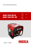
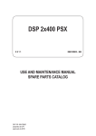
CT 350 LSX 0111 373129003 - GB USE AND MAINTENANCE MANUAL DRAFT © MOSA- 19/01/11 37312M00 preparato da UPT approvato da DITE REV.0-06/10 DESCRIPTION OF THE MACHINE M 0 CT 350 LSX CT 350 LSX CC/CV The CT 350 engine driven welder is a unit which ensures the function as: a) a current source for are welding b) a current source for the auxiliary generation The welding generator set is a source of DC electric power, driven by an internal combustion engine, which allows to perform arc welding processes with different types of electrodes and, with the CC/CV version, also wire welding. Besides, the generation set can provide ac 50 Hz auxiliary power, both three-phase and single phase, usable for the various needs associated with the welding. The engine which drives the generator set is a two-cylinder diesel type, air cooled, while the alternator is an asynchronous three-phase type. The welding current control is performed by means of a high frequency (20 kHz) “chopper” technique, while the regulation board is implemented with analogue technology. From a mechanical viewpoint, the machine is composed of a bunded basement and a roll-bar, which support the engine-alternator assembly. The canopy includes a protection cover for the front panel and two lateral doors intended to allow the routine maintenance operations. For the extraordinary maintenance the canopy can be removed in a fairly simple way. On the front panel there are the engine protection unit (EP7) and the welding control unit (WAC). Located on EP7 there are the start key and a few indicator lights which monitor the engine status. The WAC hosts the regulation knob of the welding current (which regulates also the welding voltage in the CC/CV version) and the arc force knob. The auxiliary power sockets and the welding sockets are also placed on the front panel. ENGINE PROTECTION EP7 FRONT PANEL ENGINE BASE ALTERNATOR WELDING ANALOG CONTROL WAC ROLL-BAR © MOSA REV.3-02/09 M Quality system 01 UNI EN ISO 9001 : 2008 The certifying institute, ICIM, which is a member ofthe International Certification Network IQNet, awarded the official approval to MOSA after anexamination of its operations at the head office andplant in Cusago (MI), Italy. This certification is not a point of arrival but a pledgeon the part of the entire company to maintain a levelof quality of both its products and services whichwill continue to satisfy the needs of its clients, aswell as to improve the transparency and thecommunications regarding all the company’s activesin accordance with the official procedures and inharmony with the MOSA Manual of Quality. The advantages for MOSA clients are: ·Constant quality of products and services at thehigh level which the client expects; ·Continuous efforts to improve the products andtheir performance at competitive conditions; ·Competent support in the solution of problems; ·Information and training in the correct applicationand use of the products to assure the security ofthe operator and protect the environment; ·Regular inspections by ICIM to confirm that therequirements of the company’s quality systemand ISO 9001 are being respected. All these advantages are guaranteed by the CERTIFICATE OF QUALITY SYSTEM No.0192 issued by ICIM S.p.A. - Milano (Italy ) - www.icim.it 10/10/02 M01-GB MOSA has certified its quality system according to UNI EN ISO 9001:2008 to ensure a constant, highquality of its products. This certification covers thedesign, production and servicing of engine drivenwelders and generating sets. REV.0-01/11 Index CT 350 LSX M 1 03/06/10 37310-GB M0 DESCRIPTION OF THE MACHINE M 01 QUALITY SYSTEM M 1.01 COPYRIGHT M 1.1 NOTES M 1.4 CE MARK M 1.4.1 DECLARATION OF CONFORMITY M 1.5 TECHNICAL DATA M 1.6 TECHNICAL DATA M 2 SAFETY PRECAUTIONS M 2.1 SYMBOLS M 2.5 -…. INSTALLATION AND ADVICE BEFORE USE M 2.6 INSTALLATION AND ADVICE M 2.7 INSTALLATION AND DIMENSIONS M3 UNPACKING M 4 - 4.1 TRANSPORT AND DISPLACEMENTS M 6.17 MONTAGE CTM/CTL 330 M 20 SET-UP FOR OPERATION M 21 STARTING THE ENGINE M 22 STOPPING THE ENGINE M 30 CONTROLS LEGEND M 31 CONTROLS M 33 ... WELDING ANALOG CONTROL (WAC) M 34 USE AS A WELDER M 37 USE AS A GENERATOR M 38.10 REMOTE CONTROL RC2 M 38.12 REMOTE CONTROL TC7 M 40.1 TROUBLE SHOOTING M 43... MAINTENANCE M 45 STORAGE M 46 CUST OFF M 55 RECOMMENDED ELECTRODES M 60 LEGEND ELECTRICAL SYSTEM M 61 ELECTRICAL SYSTEM Copyright © MOSA GE_, MS_, TS_, EAS M 1.01 1.0-10/02 ATTENTION This use and maintenance manual is an important part of the machines in question. The assistance and maintenance personel must keep said manual at disposal, as well as that for the engine and alternator (if the machine is synchronous) and all other documentation about the machine. We advise you to pay attention to the pages concerning the security (see page M1.1). © All rights are reserved to said Company. It is a property logo of MOSA division of B.C.S. S.p.A. All other possible logos contained in the documentation are registered by the respective owners. ➠ The reproduction and total or partial use, in any form and/or with any means, of the documentation is allowed to nobody without a written permission by MOSA division of B.C.S. S.p.A. To this aim is reminded the protection of the author’s right and the rights connected to the creation and design for communication, as provided by the laws in force in the matter. In no case MOSA division of B.C.S. S.p.A. will be held responsible for any damaga, direct or indirect, in relation with the use of the given information. 10/10/02 M1-01-GB MOSA division of B.C.S. S.p.A. does not take any responsibility about the shown information on firms or individuals, but keeps the right to refuse services or information publication which it judges discutible, unright or illegal. Notes © MOSA GE_, MS_, TS_, EAS_ M 1-1 1.0-10/02 INFORMATION Dear Customer, We wish to thank you for having bought from MOSA a high quality set. Our sections for Technical Service and Spare Parts will work at best to help you if it were necessary. To this purpose we advise you, for all control and overhaul operations, to turn to the nearest authorized Service Centre, where you will obtain a prompt and specialized intervention. ☞ In case you do not profit on these Services and some parts are replaced, please ask and be sure that are used exclusively original MOSA parts; this to guarantee that the performances and the initial safety prescribed by the norms in force are re-established. ☞ The use of non original spare parts will cancel immediately any guarantee and Technical Service obligation from MOSA. NOTES ABOUT THE MANUAL Before actioning the machine please read this manual attentively. Follow the instructions contained in it, in this way you will avoid inconveniences due to negligence, mistakes or incorrect maintenance. The manual is for qualified personnel, who knows the rules: about safety and health, installation and use of sets movable as well as fixed. INFORMATION OF GENERAL TYPE In the envelope given together with the machine and/or set you will find: the manual for Use Maintenance and Spare Parts, the manual for use of the engine and the tools (if included in the equipment), the guarantee (in the countries where it is prescribed by law). Our products have been designed for the use of generation for welding, electric and hydraulic system; ANY OTHER DIFFERENT USE NOT INCLUDED IN THE ONE INDICATED, relieves MOSA from the risks which could happen or, anyway, from that which was agreed when selling the machine; MOSA excludes any responsibility for damages to the machine, to the things or to persons in this case. Our products are made in conformity with the safety norms in force, for which it is advisable to use all these devices or information so that the use does not bring damage to persons or things. While working it is advisable to keep to the personal safety norms in force in the countries to which the product is destined (clothing, work tools, etc.). Do not modify for any motive parts of the machine (fastenings, holes, electric or mechanical devices, others..) if not duly authorized in writing by MOSA: the responsibility coming from any potential intervention will fall on the executioner as in fact he becomes maker of the machine. You must remember that, in case you have difficulties for use or installation or others, our Technical Service is always at your disposal for explanations or interventions. You must take into account that some figures contained in it want only to identify the described parts and therefore might not correspond to the machine in your possession. ☞ Notice: this manual does not engage MOSA, who keeps the faculty, apart the essential characteristics of the model here described and illustrated, to bring betterments and modifications to parts and accessories, without putting this manual uptodate immediately. 10/10/02 M 1-1 GB The manual for Use Maintenance and Spare Parts is an integrant part of the product. It must be kept with care during all the life of the product. In case the machine and/or the set should be yielded to another user, this manual must also given to him. Do not damage it, do not take parts away, do not tear pages and keep it in places protected from dampness and heat. © MOSA REV.4-10/07 M 1.4 CE MARK Any of our product is labelled with CE marking attesting its conformity to appliable directives and also the fulfillment of safety requirements of the product itself; the list of these directives is part of the declaration of conformity included in any machine standard equipment. Here below the adopted symbol: CE marking is clearly readable and unerasable and it can be either part of the data-plate (A) or placed as a sticker near the data-plate (B) A B The indication is shown in a clear, readable and indeleble way on a sticker. 10/10/02 M1-4 GB Furthermore, on each model it is shown the noise level value; the symbol used is the following: REV.0-06/10 Dichiarazione conformità Declaration of conformity Déclaration de conformité BCS S.p.A. Konformitätserklärung Declaración de conformidad CT 350 LSX CC/CV Stabilimento di Cusago, 20090 (MI) - Italia V.le Europa 59 Tel.: +39 02 903521 Fax: +39 02 90390466 Sede legale: Via Marradi 1 20123 Milano - Italia DICHIARAZIONE DI CONFORMITA' Déclaration de Conformité – Declaration of Conformity – Konformitätserklärung Conformiteitsverklaring – Declaración de Conformidad BCS S.p.A. dichiara sotto la propria responsabilità che la macchina: BCS S.p.A. déclare, sous sa propre responsabilité, que la machine: BCS S.p.A. declares, under its own responsibility, that the machine: BCS S.p.A. erklärt, daß die Aggregate: BCS S.p.A. verklaard, onder haar eigen verantwoordelijkheid, dat de machine: BCS S.p.A. declara bajo su responsabilidad que la máquina: GRUPPO ELETTROGENO DI SALDATURA / WELDING GENERATOR GRUPPO ELETTROGENO / POWER GENERATOR Marchio / Brand : _MOSA_____________________________________________ Modello / Model : ______________________________________________ Matricola / Serial number : ______________________________ è conforme con quanto previsto dalle Direttive Comunitarie e relative modifiche: est en conformité avec ce qui est prévu par les Directives Communautaires et relatives modifications: conforms with the Community Directives and related modifications: mit den Vorschriften der Gemeinschaft und deren Ergänzungen übereinstimmt: in overeenkomst is met de inhoud van gemeenschapsrichtlijnemen gerelateerde modificaties: comple con los requisítos de la Directiva Comunitaria y sus anexos: 2006/42/CE - 2006/95/CE - 2004/108/CE Nome e indirizzo della persona autorizzata a costituire il fascicolo tecnico : Nom et adresse de la personne autorisée à composer le Dossier Technique : Person authorized to compile the technical file and address : Name und Adresse der zur Ausfüllung der technischen Akten ermächtigten Person : Persoon bevoegd om het technische document , en bedrijf gegevens in te vullen Nombre y dirección de la persona autorizada a componer el expediente técnico : ing. Benso Marelli - Amministratore Delegato / CEO; V.le Europa 59, 20090 Cusago (MI) - Italy Cusago, _______________ Ing. Benso Marelli Amministratore Delegato CEO MM 083.0 M 1.4.1 REV.0-01/11 Technical data CT 350 LSX Technical data CT 350 LSX CC/CV Three-phase generation Single-phase generation Single-phase generation Single-phase generation Frequency Cos ϕ ALTERNATOR 10 kVA / 400 V / 14.4 A 5 kVA / 230 V / 21.7 A 2.5 kVA / 110 V / 22.7 A 5 kVA / 48 V / 104 A 50 Hz 0.9 Self-excited, self-regulated Type Insulating class ENGINE three-phase, asynchronous H Mark / Model Type / Cooling system Cylinders / Displacement Output max Speed Fuel consumption Engine oil capacity Starter GENERAL SPECIFICATIONS Lombardini / 12LD477.2 Diesel 4-tempi / aria 2 / 954 cm3 14 kW (19 HP) 3000 giri/min 2.5 l/h 3l Elettrico GENERATOR Tank capacity Running time (at duty cycle 60%) Protection Dimensions / max. Lxwxh (mm) * Weight * Measured acoustic power LwA (pressure LpA)* Guaranteed acoustic power LwA (pressure LpA)* 38 l 15.2 h IP 23 1230x690x925 345 Kg 94 dB(A) (69 dB(A) @ 7 m) 95 dB(A) (70 dB(A) @ 7 m) M 1.5 2000 / 14 / CE * Dimensions and weight are inclusive of all parts without wheels and towbar (CTM). POWER Declared power according to ISO 3046-1 (temperature 25°C, 30% relative humidity, altitude 100 m above sea level). It’s admitted overload of 10% each hour every 12 h. In an approximative way one reduces: of 1% every 100 m altitude and of 2.5% for every 5°C above 25°C. Lp a 1 meter = 95 dB(A) - 8 dB(A) = 87 dB(A) Lp a 4 meters = 95 dB(A) - 20 dB(A) = 75 dB(A) Lp a 7 meters = 95 dB(A) - 25 dB(A) = 70 dB(A) Lp a 10 meters = 95 dB(A) - 28 dB(A) = 67 dB(A) 03/06/10 37310-GB ACOUSTIC POWER LEVEL ATTENTION: The concrete risk due to the machine depends on the conditions in which it is used. Therefore, it is up to the enduser and under his direct responsibility to make a correct evaluation of the same risk and to adopt specific precautions (for instance, adopting a I.P.D. -Individual Protection Device) Acoustic Noise Level (LWA) - Measure Unit dB(A): it stands for acoustic noise released in a certain delay of time. This is not submitted to the distance of measurement. Acoustic Pressure (Lp) - Measure Unit dB(A): it measures the pressure originated by sound waves emission. Its value changes in proportion to the distance of measurement. The here below table shows examples of acoustic pressure (Lp) at different distances from a machine with Acoustic Noise Level (LWA) of 95 dB(A) PLEASE NOTE: the symbol when with acoustic noise values, indicates that the device respects noise emission limits according to 2000/14/CE directive. 2000 / 14 / CE REV.0-01/11 Technical data Technical data M 1.6 CT 350 LSX CT 350 LSX C.C. WELDING Duty cycle Welding current electronic regulation Open circuit voltage 350A/35% - 300A/60% - 250A/100% 20 - 350A 70V C.C. STATIC CHARACTERISTICS SIMULTANEOUS UTILISATION LIMITS WELDING CURRENT (CC) [A] 0 50 100 150 200 250 300 350 AUXILIARY POWER 3-PHASE [Kw] 8.0 8.0 7.0 5.5 3.5 2.0 0 0 AUXILIARY POWER SINGLE PHASE [Kw] 4.0 4.0 4.0 4.0 3.5 2.0 0 0 SYMBOLS AND SAFETY PRECAUTIONS © MOSA M 2 1.0-11/99 SYMBOLS IN THIS MANUAL - The symbols used in this manual are designed to call your attention to important aspects of the operation of the machine as well as potential hazards and dangers for persons and things. IMPORTANT ADVICE - Advice to the User about the safety: ☞ GE_, MS_, TS_ N.B.: The information contained in the manual can be changed without notice. Potential damages caused in relation to the use of these instructions will not be considered because these are only indicative. Remember that the non observance of the indications reported by us might cause damage to persons or things. It is understood, that local dispositions and/or laws must be respected. WARNING Situations of danger - no harm to persons or things SAFETY PRECAUTIONS DANGEROUS This heading warns of an immediate danger for persons as well for things. Not following the advice can result in serious injury or death. WARNING This heading warns of situations which could result in injury for persons or damage to things. CAUTION To this advice can appear a danger for persons as well as for things, for which can appear situations bringing material damage to things. IMPORTANT NOTE ATTENTION These headings refer to information which will assis you in the correct use of the machine and/or accessories. Do not use without protective devices provided Removing or disabling protective devices on the machine is prohibited. 26/11/99 M2GB Do not use the machine if it is not in good technical condition The machine must be in good working order before being used. Defects, especially those which regard the safety of the machine, must be repaired before using the machine. REV.2-06/10 SYMBOLS STOP - Read absolutely and be duly attentive Read and pay due attention ! GENERAL ADVICE - If the advice is not respected damage can happen to persons or things. HIGH VOLTAGE - Attention High Voltage. There can be parts in voltage, dangerous to touch. The non observance of the advice implies life danger. FIRE - Danger of flame or fire. If the advice is not respected fires can happen. HEAT - Hot surfaces. If the advice is not respected burns or damage to things can be caused. EXPLOSION - Explosive material or danger of explosion. in general. If the advice is not respected there can be explosions. WATER - Danger of shortcircuit. If the advice is not respected fires or damage to persons can be caused. SMOKING - The cigarette can cause fire or explosion. If the advice is not respected fires or explosions can be caused. ACIDS - Danger of corrosion. If the advice is not respected the acids can cause corrosions with damage to persons or things. PROHIBITIONS No harm for persons Use only with safety clothing It is compulsory to use the personal protection means given in equipment. Use only with safety clothing It is compulsory to use the personal protection means given in equipment. Use only with safety protections It is a must to use protection means suitable for the different welding works. Use with only safety material It is prohibited to use water to quench fires on the electric machines. Use only with non inserted voltage It is prohibited to make interventions before having disinserted the voltage. No smoking It is prohibited to smoke while filling the tank with fuel. No welding It is forbidden to weld in rooms containing explosive gases. ADVICE No harm for persons and things Use only with safety tools, adapted to the specific use It is advisable to use tools adapted to the various maintenance works. Use only with safety protections, specifically suitable It is advisable to use protections suitable for the different welding works. Use only with safety protections It is advisable to use protections suitable for the different daily checking works. WRENCH - Use of the tools. If the advice is not respected damage can be caused to things and even to persons. Use only with safety protections It is advisable to use all protections while shifting the machine. PRESSION - Danger of burns caused by the expulsion of hot liquids under pressure. Use only with safety protections It is advisable to use protections suitable for the different daily checking works.and/or of maintenance. ACCES FORBIDDEN to non authorizad peaple. 26/11/99 M2-1GB © MOSA M 2-1 SYMBOLS AND SAFETY PRECAUTIONS INSTALLATION AND ADVICE BEFORE USE © MOSA GE_, MS_, TS_ M 2-5 1.0-06/00 The installation and the general advice concerning the operations, are finalized to the correct use of the machine, in the place where it is used as generator group and/or welder. Stop engine when fueling Do not touch electric devices if you are barefoot or with wet clothes. ENGINE Unscrew the cap slowly to let out the fuel vapours. Slowly unscrew the cooling liquid tap if the liquid must be topped up. The vapor and the heated cooling liquid under pressure can burn face, eyes, skin. Do not fill tank completely. Wipe up spilled fuel before starting engine. Shut off fuel of tank when moving machine (where it is assembled). Avoid spilling fuel on hot engine. Sparks may cause the explosion of battery vapours CHECKING BOARD Do not smoke, avoid flames, sparks or electric tools when fueling. Always keep off leaning surfaces during work operations Static electricity can demage the parts on the circuit. An electric shock can kill ☞ FIRST AID. In case the operator shold be sprayed by accident, from corrosive liquids a/o hot toxic gas or whatever event which may cause serious injuries or death, predispose the first aid in accordance with the ruling labour accident standards or of local instructions. Skin contact Eyes contact Ingestion Suction of liquids from lungs Inhalation Wash with water and soap Irrigate with plenty of water, if the irritation persists contact a specialist Do not induce vomit as to avoid the intake of vomit into the lungs, send for a doctor If you suppose that vomit has entered the lungs (as in case of spontaneous vomit) take the subject to the hospital with the utmost urgency In case of exposure to high concentration of vapours take immediately to a non polluted zone the person involved ☞ FIRE PREVENTION. In case the working zone,for whatsoever cause goes on fire with flames liable to cause severe wounds or death, follow the first aid as described by the ruling norms or local ones. WARNING WARNING CAUTION THE MACHINE MUST NOT BE USED IN AREAS WITH EXPLOSIVE ATMOSPHERE 10/06/00 M2-5I Particular protection Useful warnings EXTINCTION MEANS Carbonate anhydride (or carbon dioxyde) powder, foam, nebulized water Avoid the use of water jets Cover eventual shedding not on fire with foam or sand, use water jets to cool off the surfaces close to the fire Wear an autorespiratory mask when heavy smoke is present Avoid, by appropriate means to have oil sprays over metallic hot surfaces or over electric contacts (switches,plugs,etc.). In case of oil sprinkling from pressure circuits, keep in mind that the inflamability point is very low. DANGEROUS Appropriated Not to be used Other indications PRECAUTION (ENGINE DRIVEN WELDER) © MOSA GE_, MS_, TS_ M 2-5- 1 1.0-03/00 INSTALLATION AND ADVICE BEFORE USE The operator of the welder is responsible for the security of the people who work with the welder and for those in the vicinity. The security measures must satisfy the rules and regulations for engine driven welders. The information given below is in addition to the local security norms. Estimate possible electromagnetic problems in the work area taking into account the following indications. 1. Telephonic wirings and/or of communication, check wirings and so on, in the immediate vicinity. 2. Radio and television receptors and transmettors. 3. Computer and other checking devices. 4. Critical devices for safety and/or for industrial checks. 5. Peapol who, for instance, use pace-maker, hearing-aid for deaf or something and else. 6. Devices used for rating and measuring. 7. The immunity of other devices in the operation area of the welder. Make sure that other used devices are compatible. If it is the case, provide other additional measures of protection. 8. The daily duration of the welding time. ATTENTION Make sure that the area is safe before starting any welding operation. ➠ ➠ ➠ ➠ ➠ ➠ ➠ ➠ ➠ ➠ ➠ ➠ ➠ ➠ operating. Do not touch any electrical parts or the electrode while standing in water or with wet hands, feet or clothes. Insulate yourself from the work surface while welding. Use carpets or other insulating materials to avoid physical contact with the work surface and the floor. Always wear dry, insulating glovers, without holes, and body protection. Do not wind cables around the body. Use ear protections if the noise level is high. Keep flamable material away from the welding area. Do not weld on containers which contain flamable material. Do not weld near refuelling areas. Do not weld on easily flamable surfaces. Do not use the welder to defrost (thaw) pipes. Remove the electrode from the electrode holder, when not welding. Avoid inhaling fumes by providing a ventilation system or, if not possible, use an approved air breather. Do not work in closed areas where there is no fresh air flow. Protect face and eyes (protective mask with suitable dark lens and side screens), ears and body (nonflamable protective clothers). 30/03/00 M2-5GB not touch any bare wires, leads or contacts as they may be live and there is danger of electric shock ➠ Do which can cause death or serious burns. The electrode and welding cables, etc. are live when the unit is © MOSA REV.1-06/07 M 2.6 INSTALLATION AND ADVICE INSTALLATION AND ADVICE BEFORE USE GASOLINE ENGINES + Use in open space, air swept or vent exhaust gases, which contain the deathly carbone oxyde, far from the work area. Check that the air gets changed completely and the hot air sent out does not come back inside the set so as to cause a dangerous increase of the temperature. 1,5 m DIESEL ENGINES + Use in open space, air swept or vent exhaust gases far from the work area. 1,5 1,5 m m UT P UICTO AOR TC DISS SU GHAA EX + Make sure that the machine does not move during the work: block it possibly with tools and/or devices made to this purpose. MOVES OF THE MACHINE + At any move check that the engine is off, that there are no connections with cables which impede the moves. PLACE OF THE MACHINE ! POSITION Place the machine on a level surface at a distance of at least 1,5 m from buildings or other plants. ATTENTION For a safer use from the operator DO NOT fit the machine in locations with high risk of flood. Please do not use the machine in weather conditions which are beyond IP protection shown both in the data plate and on page named "technical data" in this same manual. 26/11/99 M2-6GB Maximum leaning of the machine (in case of dislevel) Luftzirkulation und abmessungen Instalación y dimensiones CT 350 LSX CC/CV M 2.7 03/06/10 37310-I REV.0-06/10 Installazione e dimensioni Installation and dimensions Installation et dimensions M 3 UNPACKING 1.1-02/04 NOTE ☞ Be sure that the lifting devices are: correctly mounted, adequate for the weight of the machine with it’s packaging, and conforms to local rules and regulations. When receiving the goods make sure that the product has not suffered damage during the transport, that there has not been rough handling or taking away of parts contained inside the packing or in the set. In case you find damages, rough handling or absence of parts (envelopes, manuals, etc.), we advise you to inform immediately our Technical Service. For eliminating the packing materials, the User must keep to the norms in force in his country. 1) Take the machine (C) out of the shipment packing. Take out of the envelope (A) the user’s manual (B). 2) Read: the user’s manual (B), the plates fixed on the machine, the data plate. 30/03/00 M3GB © MOSA © MOSA REV.1-06/10 TRANSPORT AND DISPLACEMENTS COVERED UNITS ! M 4 NOTE Transportation must always take place with the engine off, electrical cables and starting battery disconnected and fuel tank empty. Be sure that the lifting devices are: correctly mounted, adequate for the weight of the machine with it’s packaging, and conform to local rules and regulations. Only authorized persons involved in the transport of the machine should be in the area of movement. DO NOT LOAD OTHER PARTS WHICH CAN MODIFY WEIGHT AND BARICENTER POSITION. IT IS STRICTLY FORBIDDEN TO DRAG THE MACHINE MANUALLY OR TOW IT BY ANY VEHICLE (model with no CTL accessory). If you did not keep to the instructions, you could damage the structure of the machine. LIFT ONLY THE MACHINE ! DANGER: LIFTING EYE IS NOT DESIGNED TO SUPPORT ADDED WEIGHT OF ROAD TOW TRAILER 30/03/00 M4GB DO NOT LIFT THE MACHINE AND TRAILER © MOSA REV.1-06/10 TRANSPORT AND DISPLACEMENTS COVERED UNITS ! M 4-1 NOTE Transportation must always take place with the engine off, electrical cables and starting battery disconnected and fuel tank empty. Be sure that the lifting devices are: correctly mounted, adequate for the weight of the machine with it’s packaging, and conform to local rules and regulations. Only authorized persons involved in the transport of the machine should be in the area of movement. DO NOT LOAD OTHER PARTS WHICH CAN MODIFY WEIGHT AND BARICENTER POSITION. IT IS STRICTLY FORBIDDEN TO DRAG THE MACHINE MANUALLY OR TOW IT BY ANY VEHICLE (model with no CTM accessory). If you did not keep to the instructions, you could damage the structure of the machine. 15/01/01 M4GB Weight max. per person: 35 kg Total max. weight; 140 kg REV.0-06/10 M 6.17 CTM330 CTL330 ASSEMBLY ! ATTENTION The CTL accessory cannot be removed from the machine and used separately (actioned manually or following vehicles) for the transport of loads or anyway for used different from the machine movements. TRAILERS The machines provided for assembling the accessory (slow towing trolley) can be towed up to a maximum speed of 40 Kms/hour on asphalted surfaces. Towing on public roads or turnpikes of any type IS EXCLUDED, because not in possesion of the requirements by national and foreign traffic norms. Nota: Lift the machine and assemble the parts as shown in the drawing CTM330 CTL330 For assembling the generating set on the trolley CTL330 please keep to following instructions: ! 3 4V 4L 4I 9 7 7A ATTENTION Do not substitute the original tires with other types. 4S 8D 8A 8C 10/06/00 M6GB 1) - Lift the generating set (by means of suitable hook). 2) - Slightly fix the jaw (3) of the parking foot to the barwith the M10x20 screws, the M10 nuts and the washers (so as to let the foot sprag go through). 3) - Split (unscrewing them) the two parts of the foot (4S-4I) to be able later to assemble them on the jaw. 4) - Introduce into the jaw (3) the upper part (4S) of the foot and screw again the lower part (4I), then tighten the screws (4V) of the jaw to the towbar and block momentaneously with the lever (4L) the whole foot. 5) - Assemble on the machine the towbar (5) complete of foot with the M10x20 screws, nuts and washers. 6) - Assemble the axle (7) to the base of the machine with the M8x20 screws and relative washers (two per part) so that their supports coincide. 7) - Introduce on the axle the antidust ring (7A) with folded edges turned toward the machine. 8) - Insert the wheel (9) on the axle paying attention to the spacer (8D) which is between the two bearings, then insert the self blocking nut (8A) and finally assemble the shutting cap (8C). 9) - Pump the tyre (9) bringing the pressure to three atms. 10) - Lower the machine to the ground and place the parking foot definitively (regulating at the best height). © MOSA 1.1-09/05 Set-up for operation (Engine diesel) Air cooled systems OIL BATH AIR FILTER BATTERY WITHOUT MAINTENANCE Connect the cable + (positive) to the pole + (positive) of the battery (after having taken away the protection), by properly tightening the clamp. Fill the air filter using the same engine oil up to the level indicated on the filter. FUEL Check the state of the battery from the colour of the warning light which is in the upper part. ! - Green colour: battery OK - Black colour: battery to be recharged - White colour: battery to be replaced DO NOT OPEN THE BATTERY. LUBRICANT RECOMMENDED OIL MOSA recommends selecting AGIP engine oil. Refer to the label on the motor for the recommended products. M 20 ATTENTION Do not smoke or use open flames during refuelling operations, in order to avoid explosions or fire hazards. Fuel fumes are highly toxic; carry out operations outdoors only, or in a wellventilated environment. Avoid accidentally spilling fuel. Clean any eventual leaks before starting up motor. Refill the tank with good quality diesel fuel, such as automobile type diesel fuel, for example. For further details on the type of diesel fuel to use, see the motor operating manual supplied. Do not fill the tank completely; leave a space of approx. 10 mm between the fuel level and the wall of the tank to allow for expansion. ! ATTENTION It is dangerous to fill the motor with too much oil, as its combustion can provoke a sudden increase in rotation speed. DRY AIR FILTER Check that the dry air filter is correctly installed and that there are no leaks around the filter which could lead to infiltrations of non-filtered air to the inside of the motor. In rigid environmental temperature conditions, use special winterized diesel fuels or specific additives in order to avoid the formation of paraffin. GROUNDING CONNECTION The grounding connection to an earthed installation is obligatory for all models equipped with a differential switch (circuit breaker). In these groups the generator star point is generally connected to the machine’s earthing; by employing the TN or TT distribution system, the differential switch guarantees protection against indirect contacts. In the case of powering complex installations requiring or employing additional electrical protection devices, the coordination between the protection devices must be verified. For the grounding connection, use the terminal (12); comply to local and/or current regulations in force for electrical installations and safety. 16/07/03 M20-R-A-GB Please refer to the motor operating manual for the recommended viscosity. REFUELLING AND CONTROL: Carry out refuelling and controls with motor at level position. 1. Remove the oil-fill tap (24) 2. Pour oil and replace the tap 3. Check the oil level using the dipstick (23); the oil level must be comprised between the minimum and maximum indicators. Check daily ! NOTE Do not alter the primary conditions of regulation and do not touch the sealed parts. ATTENTION 1. By start-up of the generator the welding circuit is immediately operative, i.e. under voltage. Make sure that there are no unwished electrical contacts between the components of the outside welding circuit (electrode, electrode holder gun, workpiece, etc…). 2. Check that at the start-up the a.c. auxiliary generation sockets do not feed any load. Open the electric protection interrupter of the generator or disconnect the plugs of the loads from the sockets. 3. START-UP Remember that when the machines with auto-idle have the signal set to “auto-idle” will remain at the minimum no. of revs (tickover) as long as no current is drawn. Drawing power will automatically raise the number of engine revs to the nominal value and likewise the tension in the alternator. Instead, by setting the auto-idle signal to “max”, the engine revs will immediately rise to the nominal value and likewise the tension in the alternator. For the machines with manual accelerator, it is necessary to accelerate the motor manually in order to reach the nominal tension. Starting is actuated using the key which is an integral part of the EP7 post on the front panel. A)-Turn the key in a clockwise direction until all the LED lights are illuminated. B)-Wait until the “OIL PRESSURE” and “BATTERY VOLTAGE” LEDs remain illuminated. If the timer lamp is used, the yellow “PREHEAT” LED comes on for the set time of the imposed settings. C)-As soon as the green “ENGINE RUNNING” LED starts to flash, actuate the key switch in a clockwise direction (momentarily in the position then with return to rest) until obtaining starting of the engine. CT 350 LSX CT 350 LSX CC/CV M 21 If the motor does not start within 15 seconds, the non starting alert will intervene: the two LEDs “Engine running” and “glow plug” will flash alternately (see motor protection description). D)-At any time it is possible to stop the engine by turning the key in an anti-clockwise direction (OFF position). In case of engine anomaly due to low oil pressure, high temperature, broken transmission belt, low fuel level or emergency the EP7 will automatically stop the engine. 4. The motor starts up at its operating speed, 3000 rpm. After start-up, allow the motor to run for a few minutes before powering on the utilities. See table; Temperature Time ≤ - 20° C da - 20° C a -10°C da - 10° C a -5°C ≥ 5° C 5 min. 2 min. 1 min. 20 sec. 5. start-up at low temperatures. The motor will normally start up without problems down to temperatures of -10° C, -15° C. In case of starting difficulty, it is possible to repeat the starting preheating for a max. time of 10 second, lightly turning the trimmer situated at the back of the EP7 in a clockwise direction (see page M39.13 relating to engine protection “trimmer/ glow plug”). For start-up and use at lower temperatures please see the engine manual or turn to our Technical Assistance Center. In case of unsuccessful start-up, do not insist for longer than 5 seconds. Wait 10 - 15 seconds before attempting another start-up. ! CAUTION RUNNING-IN During the first 50 hours of operation, do not use more than 60% of the maximum output power of the unit and check the oil level frequently, in any case please stick to the rules given in the engine use manual. 03/06/10 37310-GB REV.0-06/10 STARTING THE ENGINE STOPPING THE ENGINE REV.0-09/07 TS 350 YSX BC CT 350 LSX CC/CV M 22 STOP For shutdown under normal conditions, proceed as follows: 1. Break the welding process in course 2. Break the production of a.c. auxiliary generation dividing the loads or opening the GFI (D). 3. Let the engine run with no load for a few minutes. Set the engine speed to minimum, signal of motor speed to “auto-idle”, or accelerator to minimum for manual accelerator. 4. Turn the start key on the EP7 to the OFF position. OFF ON START EMERGENCY SHUTDOWN 12/11/07 87381-GB To stop the group in a dangerous situation, press the emergency stop button (L5) (or turn the start key (Q1) to the OFF position). To reset the knob, turn it clockwise. M 30 CONTROLS LEGENDE 4A 9 10 12 15 16 17 19 22 23 24 24A 24B 25 26 27 28 29 30 31 31A 31B 31C 32 33 34 34A 35 36 37 42 42A 47 49 54 55 55A 56 59 59A 59B 59C 59D 59E 59F 63 66 67A 68 69A 70 71 72 73 74 75 76 79 86 86A 87 88 A3 REV.1-10/07 Hydraulic oil level light Welding socket ( + ) Welding socket ( - ) Earth terminal A.C. socket Accelerator lever Feed pump 48V D.C. socket Engine air filter Oil level dipstick Engine oil reservoir cap Hydraulic oil reservoir cap Water filling cap Fuel prefilter Fuel tank cap Muffler Stop control Engine protection cover Engine cooling/alternator fan belt Oil drain tap Hydraulic oil drain tap Water drain tap Exhaust tap for tank fuel Button Start button Booster socket 12V Booster socket 24V Battery charge fuse Space for remote control Remote control Space for E.A.S. Space for PAC Fuel pump Electric start socket Reset button PTO HI Quick coupling m. PTO HI Quick coupling f. PTO HI Hydraulic oil filter Battery charger thermal switch Engine thermal switch Aux current thermal switch Supply thermal switch wire feeder42V Pre-heater (spark plug) thermal switch Supply thermal switch oil/water heather Electropump thermal switch No load voltage control Choke control Auxiliary / welding current control Cellulosic electrodes control Voltmeter relay Warning lights Selecting knob Load commut. push button Starting push button Operating mode selector Power on warning light Display Wire connection unit Selector Setting confirmation Fuel valve Oil syringe Insulation monitoring A4 B2 B3 B4 B5 C2 C3 C6 D D1 D2 E2 F F3 F5 F6 G1 H2 H6 H8 I2 I3 I4 I5 I6 I8 L L5 L6 M M1 M2 M5 M6 N N1 N2 N5 N6 O1 P Q1 Q3 Q4 Q7 R3 S S1 S3 S6 S7 T T4 T5 T7 U U3 U4 U5 U7 V V4 V5 W1 W3 Button indicating light 30 l/1' PTO HI Engine control unit EP2 E.A.S. connector Exclusion indicating light PTO HI Auxiliary current push button Fuel level light E.A.S. PCB Control unit for generating sets QEA Ground fault interrupter ( 30 mA ) Engine control unit and economiser EP1 Ammeter Frequency meter Fuse Stop switch Warning light, high temperature Arc-Force selector Fuel level transmitter Voltage commutator Fuel electro pump Engine control unit EP7 48V A.C. socket Welding scale switch Preheating indicator Y/▲ switch Start Local/Remote selector AUTOIDLE switch A.C. output indicator Emergency button Choke button Hour counter Warning level light Contactor Engine control unit EP5 CC/CV switch Voltmeter Battery charge warning light Thermal-magnetic circuit breaker/ Ground fault interrupter Pre-heat push-button Connector - wire feader Oil pressure warning light/Oil alert Welding arc regulator Starter key Derivation box Battery charge sockets Welding selector mode Siren Welding ammeter Battery Engine control unit EP4 Wire feeder supply switch Plug 230V singlephase Welding current regulator Dirty air filter warning light/indicator Earth leakage relay Analogic instrument V/Hz Current trasformer R.P.M. adjuster Polarity inverter remote control Relase coil Engine control unit EP6 Welding voltage voltmeter Polarity inverter control Oil pressure indicator Remote control switch Selection push button 30 l/1' PTO HI W5 X1 Y3 Y5 Z2 Z3 Z5 Battery voltmeter Remote control socket Button indicating light 20 l/1' PTO HI Commutator/switch, serial/parallel Thermal-magnetic circuit breaker Selection push button 20 l/1' PTO HI Water temperature indicator 10/05/01 M30-GB © MOSA Bedienelemente Mandos CT 350 LSX CC/CV M 31 03/06/10 37310-I REV.0-06/10 Comandi Controls Commandes USE © MOSA WELDING ANALOG CONTROL M 33.1 REV.0-11/07 WELDING MODE SELECTION Two welding modes can be selected by setting accordingly the mode switch on the Control Panel: Constant Current (CC) or Constant Voltage (CV). CC is used for various types of electrode welding CV is used for wire welding. All wire type welding processes can be carried out, naked or coated. CC CC (constant current) - electrodes CV CV (constant voltage) - wire ARC FORCE REGULATION Different levels of “arc force” can be featured by adjusting the arc force knob, thereby changing the arc penetration according to the electrode used and/ or welding position. Current regulation – When the CC/CV switch is in CC position, the main potentiometer regulates the welding current within the range 20 – 210A. Voltage regulation – With the CC/CV switch in CV position the main potentiometer regulates the welding voltage within the range 15 – 30V. 12/11/07 77385-GB WELDING CURRENT / VOLTAGE REGULATION USE REV.0-11/07 OPTIONAL REMOTE CONTROL The welding current can also be set from a distance using the optional remote control. Once the remote control is connected to the connector (X1), the current is controlled by the remote control. To return to front panel control remove the connector. PUSH AND SCREW TIGHT CONTACT A OPTIONAL VRD FEATURE (VRD = Voltage Reduction Device) Each time the welding process is interrupted for more than 3 seconds, the VRD feature is activated.When the welding machine is in VRD mode, the voltage at the welding sockets is kept below a safety value (typically the voltage is around 11V). When starting to weld the machine automatically exits the VRD mode. The status "VRD in" / "VRD out" is checked by a voltage monitor and indicated by a green led and a red led respectively. When the welding voltage is below 13V, i.e. the VRD is active, the green led is on and the red one is off, indicating a safe condition. During a welding process, when the voltage normally exceeds 14V, the green light is off and the red one is on, indicating the presence of a potentially dangerous voltage at the welding sockets. DESCRIPTION B Remote potentiometer - GND Remote potentiometer - cursor C Remote potentiometer - 5V ref. voltage D Remote Control presence (jumper between C and D at RC side) E Unused 5V reference voltage F M 33.1 G Welding enable from wire feeder switched ac phase A from welding gun H Welding negative voltage for remote voltmeter on wire feeder I J 44Vac phase A for wire feeder supply 44Vac phase B for wire feeder supply 12/11/07 77385-GB © MOSA WELDING ANALOG CONTROL REV.0-06/10 CT 350 LSX CT 350 LSX CC/CV USE AS WELDER M 34 This symbol (Norm EN 60974-1 security standards for arc welders) signifies that the welder can be used in areas with increased risk of electrical shock. ! ATTENTION ! ATTENTION The welding sockets, after the machine is started (see page M 21), also with no cables, are anyway under voltage. The areas, access of which is forbiden to unqualified personel, are: - the control switchboard (front) - the exhaust of the endothermic engine - the welding process. Check at the beginning of any work the electric parameters and/or the control placed on the front. Fully insert the welding cable plugs into the corresponding sockets turning them clockwise to lock them in position. PUSH AND TWIST Make sure that the ground clamp, whose cable must be connected to the + or - terminal, depending on the type of electrode, makes a good connection and is near to the welding position. Pay attention to the two polarities of the welding circuit, which must not come in electric contact between themselves REMOTE CONTROL See page M 38 ! ATTENTION To reduce the risk of electromagnetic interferences, use the minimum lenght of welding cables and keep them near and down (ex. on the floor). The welding operations must take place far from any sensitive electronic device.Make sure that the unit is earthed (see M20). In case the interference should last, adapt further disposition, such as: move the unit, use screened cables, line filters, screen the entire work area. In case the above mentioned operations are non sufficient, please contact our Technical Assistance Service. ! CAUTION With a welding cable length up to 20 m is suggested a section of 35 mm²; wìth longer cables a bigger section is required. 03/06/10 37310-GB Make sure that the ground connection (12) is efficent (when this connection is present, being necessary). See page M20. ! WARNING It is strictly forbidden to connect the group to the public mains and/or to any other source of electric power. GENERATION IN AC (ALTERNATING CURRENT) Make certain of the efficiency of the ground connection (12). - See page M20 -. Position the GFI switch to ON. +Voltage is now immediately available to the AC sockets. Verify that the voltmeter displays the nominal voltage value (at no load it is close to +10% of the nominal value). Connect the electric devices to be powered to the AC sockets, using suitable plugs and cables in good condition. + Verify that the electrical characteristics (voltage/ frequency/power) of the device being powered are compatible with those of the generator. Low frequency and/or voltage can irreparably damage some electrical devices. Verify that the ground lead of the electrical appliance/tool to be powered is correctly connected to the terminal of the plug. +For double insulation devices with the symbol , the plug’s ground terminal does not need to be grounded. THERMAL PROTECTION The monophase outputs are protected against overloads by the thermal protection (59B). When the rated current is exceeded, the protection intervenes to cut off the voltage to the AC socket. + Notes: the intervention of the thermal protection is not instantaneous, but reacts according to an overcurrent/time characteristic, whereby the greater the overcurrent the quicker the intervention. In case of intervention by the protection device, verify that the total power for the loads connected does not exceed the declared rating and decrease if necessary. Disconnect the loads and wait a few WELDING DIGITAL CONTROL M 37 minutes to allow the thermal protection to cool down. PUSH TO Before resetting by pressing RESET the central button and then connect the load again. If the protection should intervene again, replace it with another one with matching intervention current specifications and/or contact the Service Department. . Note: do not forcibly hold the central button of the thermal protection device to prevent its intervention, as this could irreparably damage the unit’s alternator. +Note: the three phase output does not require any protection against overcurrents, since it uses a self-protecting asynchronous type alternator. GROUND FAULT INTERRUPTOR SWITCH The high-sensitivity ground fault interruptor switch [G.F.I.] (30mA) (D), guarantees protection against indirect contacts due to faulty ground currents . When the G.F.I. switch picks up a faulty ground current that is higher than 30mA, it intervenes by immediately cutting off voltage to the AC sockets. In case of intervention by this protection device, reset the G.F.I. switch by moving the lever to the ON position. In case of another intervention, verify that there are no faults in the tools connected, or replace the G.F.I. switch with another one of matching specifications and/or contact the Service Department. + Notes: Verify the operation of the G.F.I. switch at least once a month by pressing the TEST button. The generator must be running and the G.F.I. lever in the ON position. SIMULTANEOUS USE The welder’s alternator permits the simultaneous use of auxiliary power and welding current. The auxiliary power available to the AC plugs (15) diminishes as the welding current drawn increases. The table on page M1.6 TECHNICAL SPECIFICATIONS shows the amount of auxiliary power available as the welding current varies. COMBINED USE The output available from the various auxiliary power sockets is limited, not only by the declared output of the unit but also by the capacity of each individual socket. 09/04/02 M37DSP-GB REV.1-06/10 USE AS A GENERATOR REV.2-09/10 REMOTE CONTROL RC2 (PL Version) RC2/90° (PL Version) ACCESSORY USE M 38.10 PUSH AND SCREW TIGHT PUSH AND SCREW TIGHT The remote control RC, which regulates the welding current in the CC (STICK welding) mode and the welding voltage in the CV (MIG/MAG welding), is connected to the front panel by means of a multipole connector. Adjust the welding current control knob to the correct current for the diameter and type of electrode being welded. ! ATTENTION When the RC is not used, it is necessary to disconnect the multipole connector 09/04/02 M38GB When the remote control is connected to the remote control connector (8), it is functional and automatically excludes the front panel regulation. The remote control can also be connected to the connector on the wire feeder front panel but in this case it is necessary to switch the wire feeder commutator so it can operate. REV.0-06/10 ACCESSORY USE REMOTE CONTROL TC7 M 38.12 PUSH AND SCREW TIGHT The remote control device for regulating the welding current is connected to the front panel by means of a multipole connector. Position welding current adjusting (T) knob at the necessary current value for the diameter and type of electrode. 09/11/99 M38GB When the remote control is connected to the remote control connector (8), it is functional and automatically excludes the front panel regulation. PROTECTIONS © MOSA EP7 ENGINE PROTECTION M 39.13 REV.0-10/07 Description The EP7 includes the basic safeguards to protect an DIESEL engine. The EP7 features 7 LEDs, 3 Static Outputs and a 30A Key Switch. The EP7 monitors an Oil Pressure-switch, Temperatureswitch, Fuel Level-switch, Charger Alternator Voltage, and an Emergency-switch. Specification DC Supply, Battery Plant Static Outputs (short circuit proof) Key Switch Rating Dimensions-DIN 96 Size Weight Operating Temperature Operating Humidity 8V up to 36 Vdc 200 mAdc 30 A (30 secs)/80 A (5 secs) 72X72X55 (ex switch /key) 300 gr -30° C /+70° C 96% (non-condensing) [ENGINE RUNNING] green LED This LED blinks for 15 seconds, indicating that the EP7 is ready to start the engine (you have to turn the key to start). If the engine does not run within 15 seconds, the "Starting Failure" alarm will take place. This LED illuminates continuously if the engine runs. [PREHEAT] yellow LED This indicator illuminates during the Pre-Glow cycle (10 secs to 60 secs). [EMERGENCY] red LED This LED illuminates continuously when a shut down has been caused by the Emergency switch. [KEY-SWITCH] OFF position [ALTERNATOR FAILURE] red LED This LED illuminates before engine starting or if a Belt Break shut down occurs (than 20 secs). [KEY-SWITCH] Pre-Heat position [KEY-SWITCH] START position [OIL PRESSURE] red LED This LED illuminates before engine starting or if an Oil Pressure shut down occurs. [FUEL LEVEL] red LED This LED blinks when a low fuel condition occurs. This LED illuminates continuously to indicate a shut down, if the switch has been closed for more than 5 minutes. [STARTING FAILURE ALARM] indication These 2 LEDs blink alternatevely (slowly) to indicate a starting failure alarm. [OPTIONAL ALARM] indication These 2 LEDs blink alternatevely (quickly) to indicate the intervention of the alarm. [TEMPERATURE] red LED This LED illuminates when an High Temperature shut down occurs. ALARM OUTPUT (anticlockwise) Glow setting STOP SOLENOID (clockwise) ALARM OUTPUT (STOP SOLENOID) VALVE OR REGULATOR PREHEAT FUEL LEVEL AUXILIARY OUTPUT EMERGENCY TEMPERATURE OIL PRESSURE STARTER Key-switch (near view) CHARGER ALTERNATOR ENGINE STARTING FUSE 07/05/01 M39GB 5A FUSE Replace the welding control board ATTENTION For the CT 230 only, there is a risk of failure propagation towards the chopper. Before replacing this board please check that the chopper works properly. If not replace both. P4 Lack of welding Full welding power (without Failure in the control or In order to check the proper operation of these circuits it is necessary to current control current control) regardless drive circuits of the wel- use specific test and troubleshooting tools. Anyway, a visual inspection of the knob position ding control board coul be enough to localise possible damages caused by a failure. In case of evidence of damages consider the suggested action. 07/02/11 M40CT_GB P5 No welding arc No open circuit voltage or Hall sensor failed welding available current low or negligible. With auto-idle installed, the r.p.m. never slows-down to idle. Trouble shooting Disconnect the Hall sensor from the welding control board (on the WAC Replace the Hall sensor or within the electrical box, as applicable) and check that, in this condition, the open circuit voltage reading is correct. When the VRD is installed, the voltage goes to VRD value. If a resistive load bank is available, check that it is possible draw power (do not exceed 100A). If the Auto-idle is installed, in this condition the machine does not exit the idle. In any case, don’t try to weld with the Hall sensor disconnected. If the test gives positive result, consider the indicated action. Replace the welding control board ATTENTION For the CT 230 only, there is a risk of failure propagation towards the chopper. Before replacing this board please check that the chopper works properly. If not replace both. P3 No welding arc No open circuit voltage Failure in the control or In order to check the proper operation of these circuits it is necessary to drive circuits of the wel- use specific test and troubleshooting tools. Anyway, a visual inspection ding control board coul be enough to localise possible damages caused by a failure. In case of evidence of damages consider the suggested action. Failed power supply wi- With the machine running, by means of a multimeter, check if there is a Replace the welding control board thin the welding control voltage of 5VDC ± 0,125V between the contacts 1 (-) and 2 (+) on the circular connector of the front panel, after having set the remote control board (WAC) switch in ON position. In case of lack of voltage or condition not satisfied consider the suggested action. WHAT TO DO P2 No welding arc No open circuit voltage (applicable only to machines without WAC) VERIFICATIONS Failed power supply wi- With the machine running, by means of a multimeter, check if there is a Replace the welding control board of the thin the welding control voltage of 5VDC ± 0,125V between the contacts A (-) and C (+) on the WAC board (WAC) circular connector of the WAC. In case of lack of voltage or condition not satisfied consider the suggested action. ASSOCIATED SYMPTOMS POSSIBLE CAUSE P1 No welding arc No open circuit voltage (applicable only to machines with WAC) PROBLEM REV.0-02/11 CT M 40.1 The open circuit voltage is Cable interruption betwezero en the WAC or the welding control board (as applicable depending on the machine type) and the welding sockets With the machine stopped, extract the connector plugged to J1 of the WAC / Wel- Fix the cabling or replace it. ding control board (as applicable depending on the machine type). Check by means of a multimeter the continuity between pin 5 of the connector and the negative welding socket. The resistive value shall be < 4 ohm if there is a filter board behind the sockets, otherwise shall be < 0.5 ohm. In case of condition not satisfied take the indicated corrective action Trouble shooting 07/02/11 M40CT_GB P10 No welding arc P9 Minimum welding The welding current in CC current in CC mode mode with the knob at betoo high ginning of scale is too high and changes when turning the arc force knob (if present, switch in ON position) With the machine stopped, extract the connector plugged to J1 of the WAC / Wel- Fix the cabling or replace it. ding control board (as applicable depending on the machine type). Check by means of a multimeter the continuity between pin 6 of the connector and the positive welding socket. The resistive value shall be < 4 ohm if there is a filter board behind the sockets, otherwise shall be < 0.5 ohm. In case of condition not satisfied take the indicated corrective action. Check by means of a multimeter (stopped machine) the resistence value between Replace the EMC filter board positive welding socket and the corresponding faston connector on the filter board. The condition to check is: ohmic value between + welding socket and + board faston (the one to which the red cables are connected) < 4 ohm In case of condition not satisfied take the indicated corrective action. The welding current in CC Failure in the EMC filter mode with the knob at be- board on the welding soginning of scale is too high ckets and changes when turning the arc force knob (if present, switch in ON position) P8 Cable interruption between the WAC or the welding control board (as applicable depending on the machine type) and the welding sockets Check by means of a multimeter (stopped machine) the resistence value between Replace the EMC filter board positive welding socket and the corresponding faston connector on the filter board. The condition to check is: ohmic value between - welding socket and - board faston (the one to which the black cables are connected) < 4 ohm In case of condition not satisfied take the indicated corrective action. No welding arc The open circuit voltage is Failure in the EMC filter board on the welding so(applicable to the zero ckets machines provided with the filter board on the welding sockets) P7 Minimum welding current in CC mode too high (applicable to the machines provided with the filter board on the welding sockets) Check by means of a multimeter (stopped machine) the resistence value between Replace the EMC filter board positive welding socket and the corresponding faston connector on the filter board. The condition to check is: ohmic value between + welding socket and + board faston (the one to which the red cables are connected) < 4 ohm In case of condition not satisfied take the indicated corrective action. WHAT TO DO The open circuit voltage in Failure in the EMC filter CV mode is the same as for board on the welding sothe CC mode, regardless of ckets the control knob position VERIFICATIONS Lack of voltage control in CV mode (applicable to the CC-CV machines provided with filter board) ASSOCIATED SYMPTOMS POSSIBLE CAUSE P6 PROBLEM REV.0-02/11 CT M 40.2 ASSOCIATED SYMPTOMS POSSIBLE CAUSE WHAT TO DO In order to check the proper operation of the Hall sensor it is necessary to use specific Replace the Hall sensor test and troubleshooting tools. Anyway, a visual inspection coul be enough to localise possible damages, with particular reference to possible wear of the cable end coming out of the Hall sensor potting. Please check also the connector contacts crimping at the opposite end of the cable. In case of evidence of damages consider the suggested action VERIFICATIONS When turning the knob the current setting (and the voltage setting, if applicable) do not change or change irregularly The potentiometer which Check if the regulation through remote control works properly. If confirmed, consider the Replace the potentiometer regulates the welding suggested corrective action. current (and the welding voltage, when applicable) is faulty Disconnect the chopper cable from the connector J3 of the WAC. Check that the open Replace the chopper circuit voltage is < 1V. If not put a light resistive load at the welding output (few kohms are enough) and check again the previous condition. If it is not satisfied the chopper is faulty. In this case consider the suggested corrective action. Trouble shooting 07/02/11 M40CT_GB P14 Knob irregular or missing current adjustment P13 Lack of wel- Full welding power (without Chopper faulty ding current current control) regardless control (ap- of the knob position plicable only to CT 230) P12 Lack of wel- Full welding power (without Chopper and/or driver Disconnect the chopper cable from the connector J3 of the WAC. Check that the open Replace the chopper and the circuit voltage is < 1V. If not put a light resistive load at the welding output (few kohms driver board ding current current control) regardless board failed are enough) and check again the previous condition. If it is not satisfied the chopper is control (ap- of the knob position faulty. plicable only If a welding load bank and a clamp DC amp meter are available, another test can be to CT 350) done to localise the failed section/s. To this purpose set the load bank for a current of a few tens of amps and measure the current at the output of each chopper section (the group of cables which connect the chopper to one end of the welding current leveling reactor). The sections through which the current flows are failed or improperly driven by the driver board. If the test confirms this type of failure consider the suggested corrective action. P11 Lack of wel- Full welding power (without Hall sensor failed ding current current control) regardless control of the knob position. When the auto-idle is installed, the machine remains at low r.p.m. PROBLEM REV.0-02/11 CT M 40.3 © MOSA REV.0-06/10 M 43 MAINTENANCE ! WARNING Have qualified personnel do maintenance and troubleshooting work. Stop the engine before doing any work inside the machine. If for any reason the machine must be operated while working inside, pay attention moving parts, hot parts (exhaust manifold and muffler, etc.) electrical parts which may be unprotected when the machine is open. lRemove guards only when necessary to perform maintenance, and replace them when the maintenance requiring their removal is complete. lUse suitable tools and clothes. lDo not modify the components if not authorized. - See pag. M1.1 l NOTE By maintenance at care of the utilizer we intend all the operatios concerning the verification of mechanical parts, electrical parts and of the fluids subject to use or consumption during the normal operation of the machine. For what concerns the fluids we must consider as maintenance even the periodical change and or the refills eventually necessary. Maintenance operations also include machine cleaning operations when carried out on a periodic basis outside of the normal work cycle. The repairs cannot be considered among the maintenance activities, i.e. the replacement of parts subject to occasional damages and the replacement of electric and mechanic components consumed in normal use, by the Assistance Authorized Center as well as by MOSA. The replacement of tires (for machines equipped with trolleys) must be considered as repair since it is not delivered as standard equipment any lifting system. The periodic maintenance should be performed according to the schedule shown in the engine manual. An optional hour counter (M) is available to simplify the determination of the working hours. ! IMPORTANT In the maintenance operations avoid that polluting substances, liquids, exhausted oils, etc. bring damage to people or things or can cause negative effects to surroindings, health or safety respecting completely the laws and/ or dispositions in force in the place. ENGINE and ALTERNATOR PLEASE REFER TO THE SPECIFIC MANUALS PROVIDED. Every engine and alternator manufacturer has HOT surface can hurt you maintenance intervals and specific checks for each model: it is necessary to consult the specific engine or alternator USER AND MAINTENANCE manual. VENTILATION Make certain there are no obstructions (rags, leaves or other) in the air inlet and outlet openings on the machine, alternator and motor. ELECTRICAL PANELS Check condition of cables and connections daily. Clean periodically using a vacuum cleaner, DO NOT USE COMPRESSED AIR. DECALS AND LABELS All warning and decals should be checked once a year and replaced if missing or unreadable. STRENUOUS OPERATING CONDITIONS Under extreme operating conditions (frequent stops and starts, dusty environment, cold weather,extended periods of no load operation, fuel with over 0.5% sulphur content) do maintenance more frequently. BATTERY WITHOUT MAINTENANCE DO NOT OPEN THE BATTERY The battery is charged automatically from the battery charger circuit suppplied with the engine. Check the state of the battery from the colour of the warning light which is in the upper part. - Green colour: battery OK - Black colour: battery to be recharged - White colour: battery to be replaced ! NOTE THE ENGINE PROTECTION NOT WORK WHEN THE OIL IS OF LOW QUALITY BECAUSE NOT CHARGED REGULARLY AT INTERVALS AS PRESCRIBED IN THE OWNER’S ENGINE MANUAL. 05/09/05 M43GB MOVING PARTS can injure STORAGE © MOSA GE_, MS_, TS_ M 45 1.0-06/00 In case the machine should not be used for more than 30 days, make sure that the room in which it is stored presents a suitable shelter from heat sources, weather changes or anything which can cause rust, corrosion or damages to the machine. ☞ Have qualified personnel prepare the machine for storage. GASOLINE ENGINE Start the engine: lt will run until it stops due to the lack of fuel. Drain the oil from the engine sump and fill it with new oil (see page M25). Pour about 10 cc of oil into the spark plug hole and screw the spark plug, after having rotated the crankshaft several times. Rotate the crankshaft slowly until you feel a certain compression, then leave it. In case of necessity for first aid and of fire prevention, see page. M2.5. IMPORTANT In the storage operations avoid that polluting substances, liquids, exhausted oils, etc. bring damage to people or things or can cause negative effects to surroindings, health or safety respecting completely the laws and/or dispositions in force in the place. In case the battery, for the electric start, is assembled, disconnect it. Clean the covers and all the other parts of the machine carefully. Protect the machine with a plastic hood and store it in o dry place. DIESEL ENGINE For short periods of time it is advisable, about every 10 days, to make the machine work with load for 15-30 minutes, for a correct distribution of the lubricant, to recharge the battery and to prevent any possible bloking of the injection system. For long periods of inactivity, turn to the after soles service of the engine manufacturer. Clean the covers and all the other parts of the machine carefully. 30/00/00 M45GB Protect the machine with a plastic hood and store it in a dry place. CUST OFF © MOSA ☞ GE_, MS_, TS_ M 46 1.0-03/00 Have qualified personnel disassemble the machine and dispose of the parts, including the oil, fuel, etc., in a correct manner when it is to be taken out of service. As cust off we intend all operations to be made, at utilizer’s care, at the end of the use of the machine. This comprises the dismantling of the machine, the subdivision of the several components for a further reutilization or for getting rid of them, the eventual packing and transportation of the eliminated parts up to their delivery to the store, or to the bureau encharged to the cust off or to the storage office, etc. The several operations concerning the cust off, involve the manipulation of fluids potentially dangerous such as: lubricating oil and battery electrolyte. In case of necessity for first aid and fire prevention, see page M2.5. IMPORTANT In the cust-off operations avoid that polluting substances, liquids, exhausted oils, etc. bring damage to people or things or can cause negative effects to surroindings, health or safety respecting completely the laws and/or dispositions in force in the place. The dismantling of metallic parts liable to cause injuries or wounds, must be made wearing heavy gloves and using suitable tools. The getting rid of the various components of the machine must be made accordingly to rules in force of law a/o local rules. Particular attention must be paid when getting rid of: lubricating oils, battery electrolyte, and inflamable liquids such as fuel, cooling liquid. The machine user is responsible for the observance of the norms concerning the environment conditions with regard to the elimination of the machine being cust off and of all its components. In case the machine should be cust off without any previous disassembly it is however compulsory to remove: - tank fuel - engine lubricating oil - cooling liquid from the engine - battery 30/03/00 M45GB NOTE: MOSA is involved with custing off the machine only for the second hand ones, when not reparable. This, of course, after authorization. RECOMMENDED ELECTRODES © MOSA (In accordance with A.W.S Standard) MS_, TS_ M 55 1.0-10/03 The information here below are to be intended only as indicative since the above norm is much larger. For further details please see the specific norms and/or the manufacturers of the product to be used in the welding process. RUTILE ELECTRODES: E 6013 Easily removable fluid slag, suitable foe welding in all position. Rutile electrodes weld in d.c. with both polarities (electrode holder at + or -) and in a.c.. Suitable for soft steels R-38/45 kg/mm2 . Also for soft steels of lower quality. BASIC ELECTRODES: E 7015 Basic electrrodes wels onlu in d.c. with inverse polarity (+ on the electrode holder) ; there are also types for a.c. Suitable for impure carbon steels. Weld in all position. HIGH YIELD BASIC ELECTRODES: E 7018 The iron contained in the coating increases the quality of metal added. Good mechanical properties. Weld in all position. Electrode holder at + (inverse polarity). Wld deposit of nice aspect, also vertical. Workable; high yield. Suitable for steels with high contens of sulphur (impurities). CELLULOSIC ELECTRODES: E 6010 Cellulosic electrodes weld only in d.c. with polarity + electrode holder - ground clamp. Special for steels run on pipes with R max 55 kg/mm2. Weld in all position. volatile slag. ELECTRODES IDENTIFICATION ACCORDING TO A.W.S. STANDARDS E XX Y Z 2 digits: type of coating and electric power conditions. (see table 3) symbol for "Coated electrode" 2÷3 digits: tesile strenght of the weld deposit. (see table 1) Strenght Number K.s.l. 60 70 80 90 100 110 120 60.000 70.000 80.000 90.000 100.000 110.000 120.000 Kg/mm2 42 49 56 63 70 77 84 N° 10 11 12 13 14 15 16 18 20 24 27 28 Table 1 30 1 2 3 Table 2 for all positions for plane and verticl for plane posotion only Descrizione Cellulose electrodes for d.c. Cellulose electrodes for a.c. Rutile electrode for d.c. Rutile electrode for a.c. High yield rutile electrodes Basic electrodes for d.c. Basic electrodes for c.a. High yield basic electrodes for d.c. (inverse polarity) Acid electrodes for flat or front position welding for d.c. (- pole) and for a.c. High yield rutile electrodes for flat or front plane position welding for d.c. and a.c. High yield acid electrodes for flat or front plane position welding for d.c. (- pole) and a.c.. High yield basic electrodes for flat or front plane position welding for d.c. (inverse polarity) Extra high yield acid electrodes, extra high penetration if required, for flat position welding only for d.c. (- pole) and a.c. Table 3 10/10/03 M55GB 1 digits: welding positions. (see table 2) M 60 ELECTRICAL SYSTEM LEGENDE REV.7-10/09 A B C D E F G H I L M N P Q R S T U V Z X W Y : : : : : : : : : : : : : : : : : : : : : : : Alternator Wire connection unit Capacitor G.F.I. Welding PCB transformer Fuse 400V 3-phase socket 230V 1phase socket 110V 1-phase socket Socket warning light Hour-counter Voltmeter Welding arc regulator 230V 3-phase socket Welding control PCB Welding current ammeter Welding current regulator Current transformer Welding voltage voltmeter Welding sockets Shunt D.C. inductor Welding diode bridge A1 B1 C1 D1 E1 F1 G1 H1 I1 L1 M1 N1 O1 P1 Q1 R1 S1 T1 U1 V1 Z1 W1 X1 Y1 : : : : : : : : : : : : : : : : : : : : : : : : Arc striking resistor Arc striking circuit 110V D.C./48V D.C. diode bridge E.P.1 engine protection Engine stop solenoid Acceleration solenoid Fuel level transmitter Oil or water thermostat 48V D.C. socket Oil pressure switch Fuel warning light Battery charge warning light Oil pressure warning light Fuse Starter key Starter motor Battery Battery charge alternator Battery charge voltage regulator Solenoid valve control PCBT Solenoid valve Remote control switch Remote control and/or wire feeder socket Remote control plug A2 B2 C2 D2 E2 F2 G2 H2 I2 L2 M2 N2 O2 P2 Q2 R2 S2 T2 U2 V2 Z2 W2 X2 Y2 : : : : : : : : : : : : : : : : : : : : : : : : Remote control welding regulator E.P.2 engine protection Fuel level gauge Ammeter Frequency meter Battery charge trasformer Battery charge PCB Voltage selector switch 48V a.c. socket Thermal relay Contactor G.F.I. and circuit breaker 42V EEC socket G.F.I. resistor T.E.P. engine protection Solenoid control PCBT Oil level transmitter Engine stop push-button T.C.1 Engine start push-buttonT.C.1 24V c.a. socket Thermal magnetic circuit breaker S.C.R. protection unit Remote control socket Remote control plug A3 B3 C3 D3 E3 F3 G3 H3 I3 L3 M3 N3 O3 P3 Q3 R3 S3 T3 U3 V3 Z3 W3 X3 Y3 : : : : : : : : : : : : : : : : : : : : : : : : Insulation moitoring E.A.S. connector E.A.S. PCB Booster socket Open circuit voltage switch Stop push-button Ignition coil Spark plug Range switch Oil shut-down button Battery charge diode Relay Resistor Sparkler reactor Output power unit Electric siren E.P.4 engine protection Engine control PCB R.P.M. electronic regulator PTO HI control PCB PTO HI 20 l/min push-button PTO HI 30 l/min push-button PTO HI reset push-button PTO HI 20 l/min indicator A6 B6 C6 D6 E6 F6 G6 H6 I6 L6 M6 N6 O6 P6 Q6 R6 S6 T6 U6 V6 Z6 W6 X6 Y6 : : : : : : : : : : : : : : : : : : : : : : : : Commutator/switch Key switch, on/off QEA control unit Connector, PAC Frequency rpm regulator Arc-Force selector Device starting motor Fuel electro pump 12V c.c. Start Local/Remote selector Choke button Switch CC/CV Connector – wire feeder 420V/110V 3-phase transformer Switch IDLE/RUN Hz/V/A analogic instrument EMC filter Wire feeder supply switch Wire feeder socket DSP chopper PCB Power chopper supply PCB Switch and leds PCB Hall sensor Water heather indicator Battery charge indicator A4 B4 C4 D4 E4 F4 G4 H4 I4 L4 M4 N4 O4 P4 Q4 R4 S4 T4 U4 V4 Z4 W4 X4 Y4 : : : : : : : : : : : : : : : : : : : : : : : : PTO HI 30 l/min indicator PTO HI reset indicator PTO HI 20 l/min solenoid valve PTO HI 30 l/ min solenoid valve Hydraulic oil pressure switch Hycraulic oil level gauge Preheating glow plugs Preheating gearbox Preheating indicator R.C. filter Heater with thermostat Choke solenoid Step relay Circuit breaker Battery charge sockets Sensor, cooling liquid temperature Sensor, air filter clogging Warning light, air filter clogging Polarity inverter remote control Polarity inverter switch Transformer 230/48V Diode bridge, polarity change Base current diode bridge PCB control unit, polarity inverter A7 B7 C7 D7 E7 F7 G7 H7 I7 L7 M7 N7 O7 P7 Q7 R7 S7 T7 U7 V7 Z7 W7 X7 Y7 : : : : : : : : : : : : : : : : : : : : : : : : Transfer pump selector AUT-0-MAN Fuel transfer pump "GECO" generating set test Flooting with level switches Voltmeter regulator WELD/AUX switch Reactor, 3-phase Switch disconnector Solenoid stop timer "VODIA" connector "F" EDC4 connector OFF-ON-DIAGN. selector DIAGNOSTIC push-button DIAGNOSTIC indicator Welding selector mode VRD load 230V 1-phase plug V/Hz analogic instrument Engine protection EP6 G.F.I. relay supply switch Radio remote control receiver Radio remote control trasnsmitter Isometer test push-button Remote start socket A5 B5 C5 D5 E5 F5 G5 H5 I5 L5 M5 N5 O5 P5 Q5 R5 S5 T5 U5 V5 Z5 W5 X5 Y5 : : : : : : : : : : : : : : : : : : : : : : : : Base current switch Auxiliary push-button ON/OFF Accelerator electronic control Actuator Pick-up Warning light, high temperature Commutator auxiliary power 24V diode bridge Y/s commutator Emergency stop button Engine protection EP5 Pre-heat push-button Accelerator solenoid PCB Oil pressure switch Water temperature switch Water heater Engine connector 24 poles Electronic GFI relais Release coil, circuit breaker Oil pressure indicator Water temperature indicator Battery voltmeter Contactor, polarity change Commutator/switch, series/parallel A8 B8 C8 D8 E8 F8 G8 H8 I8 L8 M8 N8 O8 P8 Q8 R8 S8 T8 U8 V8 Z8 W8 X8 Y8 : Transfer fuel pump control : Ammeter selector switch : 400V/230V/115V commutator : 50/60 Hz switch : Cold start advance with temp. switch : START/STOP switch : Polarity inverter two way switch : Engine protection EP7 : AUTOIDLE switch : AUTOIDLE PCB : A4E2 ECM engine PCB : Remote emergency stop connector : V/A digital instruments and led VRD PCB : Water in fuel : Battery disconnect switch : Inverter : Overload led : Main IT/TN selector : NATO socket 12V : Diesel pressure switch : Remote control PCB : Pressure turbo protection : : 26/07/04 M60GB © MOSA CT 350 LSX CT 350 LSX CC/CV M 61.1 03/06/10 37310-I REV.0-06/10 Schema elettrico Electric diagram Schemas electriques CT 350 LSX CT 350 LSX CC/CV M 61.2 03/06/10 37310-I REV.0-04/05 Schema elettrico Electric diagram Schemas electriques CT 350 LSX CT 350 LSX CC/CV M 61.3 03/06/10 37310-I REV.0-06/10 Schema elettrico Electric diagram Schemas electriques CT 350 LSX CT 350 LSX CC/CV M 61.4 03/06/10 37310-I REV.0-06/10 Schema elettrico Electric diagram Schemas electriques